1
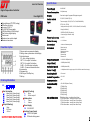
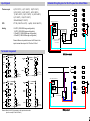
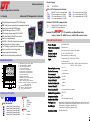
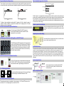
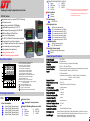
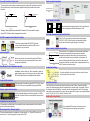
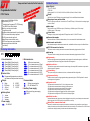
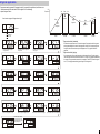
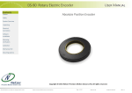
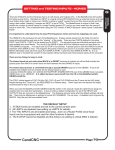
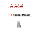
Single Loop Controls Product Catalog
DTC
DTA
TEMPERATURE CONTROLLER
SOLID STATE RELAY
[email protected]
Tel: (401) 234-0814
Fax: (401) 244-7737
www.dtHeatersandControls.com
CE
DTB
Low Cost Version
Digital Temperature Controller
DTB Series
Four digits PID
Selectable input(TC,RTD,Analog)
PID with auto-tuning
Accuracy 0.5%F.S
90~260 VAC Power supply
SSR drive/Relay/4-20mA output
Dual line four digits display
Panel mount
Maximum two control outputs
Maximum two alarms
2
3
1 ALM2
7
5
6
4
1:Process value or parameter dispaly
2:Setting value or parameter value display
3:Indication lamps
AT---Auto-tuning indication
OUT1---For output 1 indication
OUT2---For output 2 indication
ALM1 ---For first alarm indication
ALM 2---For second alarm indication
4:Increase key
5:Decrease key
6:Shift key or Run/Stop key
7:Set key
Ordering Information
DTB 1
2
3
4
5
1:Size Information
48 :
49 :
72 :
96 :
94 :
48mm(Width)*48mm(Height)
48mm(Width)*96mm(Height)
72mm(Width)*72mm(Height)
96mm(Width)*96mm(Height)
96mm(Width)*48mm(Height)
2:Output 1(Heating)
R:
V:
D:
Relay
SSR drive
4-20mA
Remark: When OUT1 selected as 4-20mA, OUT2 is not available.
Power Supply
:90~260VAC
Power Consumption
:5 VA(Maximum)
Display
:Dual Line four digits.7 segments LED display in degrees C
Control method
:P,PID,PI, PD,ON/OFF(P=0)
Input
:Thermocouple(K,J,R,S,B,E,N,T,U,L,PLII,W5Re/W26Re)
RTD(Pt100, JPT100)
Voltage and Current(0-5VDC,1-5VDC,0-20mADC,4-20mADC)
Panel Description
1
Specifications
Output
:Relay(3A /220VAC)
SSR DRIVE(12VDC 50mA max)
Current output(4-20mA/0-10mA)
Measuring Accuracy
:0.5%F.S
Control Accuracy
:+/- 1 Celsious
Alarm output
:1 alarm or 2 alarms optional
Alarm mode
:Deviation high
Deviation low
Deviation high/low
Band alarm
Process high
Process low
Proportional band(P)
:0.1-999.9/1-9999(default 30)
Integral time(I)
:1-3600S(default 240S)
Derivative times(D)
:1-3600S(default 60S)
Control Time(T)
:1-100S(default 20S for replay output, 2S for SSR drive and 4-20mA output)
Sampling time(T)
:0.5 second
Ambient Temperature
:0 C~50 C
Memory retention
:yes
Ambient humidity
:45%-85% RH(None Freeze)
Weight
:DTB-48(0.17kg)
DTB-49(0.22kg)
DTB-94(0.22kg)
DTB-72(0.22kg)
DTB-96:(0.31kg)
3:Output 2(Cooling)
R:
N:
Relay
Without output 2
4:Alarm options
1:
2:
1 alarm
2 alarms
5:Power Supply
96: 90~260VAC
6 :Auxiliary Power Supply
24: 24VDC AUX power
N:
Without auxiliary power
Size and dimensions
0
0
:DTB48--48mm*48mm cutout(45mm*45mm*78mm)
DTB-49--48mm*96mm cutout(45mm*91.5mm*70mm)
DTB-72--72mm*72mm cutout(67.5mm*67.5mm*92mm)
DTB-96--96mm*96mm cutout(91.5mm*91.5mm*70mm)
DTB-94--96mm*48mm cutout(91.5mm*45mm*70mm)
2
Detailed Wiring Diagram For Most Popular Size 48mm*48mm
Input Signals
:K(0 0C -1372 0C) J(0 0C -1200 0C) R(0 0C-1769 0C)
S(0 0C-1769 0C) B( 0 0C -1820 0C) E(0 0C -1000 0C)
T(-199 0C-400 0C) N( 0 0C -1300 0C) U( -199 0C -600 0C)
L(0 0C -900 0C) PLII(0 0C -1390 0C)
W5Re/W26Re(0 0C-2320 0C)
Thermocouple
:PT100(-199.9 0C -649.0 0C)
RTD
Jpt100(-199.9 C -649.0 0C)
8
Alarm/
out2
9
3
11
- G2
4
90~260V ~
AC
- G2
11
Alarm/
OUT2
- G2
2
(+)
2
Earth
Ground It could be change by your
required Watts or Amps
4
-
INPUT
10
5
11
+
12
-
OUT
6
3
+
Over-Current Fuse
Neutral
6
12
L
A
RTD
B
TC
Voltage
Current
B
1
7
Alarm
90~260VAC
N
2
8
3
9
4
10
OBJECT BEING CONTROLLED
Thermocouple
10
1
'7%-96
HEATER
2
5
3
+ G1
12
- G2
Thermal Fuse
6
+ G1
OUT1
15
- G2
Remark:Parallel a 250 Ohm resistor to the input terminal when
input is current(0-10mA/4-20mA)
11
+
12
-
7
8
A
RTD
B
TC
Voltage
Current
B
Earth
Ground
or Power Module
_
16
OUT
RELAY
5
14
6
4
+
A
RTD
B
TC
Voltage
Current
B
_
8
11
13
+
16
-
Alarm/
OUT2
4
7
5
11
6
- G2
10
9
+ G1
15
4
NO
5
14
OUTPUT
+ G1
9
NC
90~260V ~
AC
+ G1
12
OUT1 G2 +
3
13
OUT1
A
RTD
B
TC
Voltage
Current
B
1
'7%-49
'7%-94
4
_
7
9
10
5
6
9
ALM2
8
_
14
90~260V ~
AC
7
+
13
3
ALM1
+
OUTPUT
8
- G2
'7%-48
2
G1
+ G1
2
SSR Drive output
3
12
Alarm
Line
2
+ G1
(-)
AC SOLID
STATE RELAY
90~260VAC
1
10
Thermocouple
24-240VAC 40A
1
'7%-72
7
OBJECT BEING CONTROLLED
1
Terminal Arrangement
90~260V ~
AC
N
Thermal Fuse
or Thermostat
Remark:Be sure to parallel connect a 250 ohm to the
input terminal when input is 0-10mA or 4-20mA
1
90~260VAC
HEATER
:0-5VDC(-1999-9999 range configurable)
1-5VDC(-1999-9999 range configurable)
0-10mADC(-1999-9999 range configurable)
4-20mADC(-1999-9999 range configurable)
Analog
L
Relay output
3
Advanced Version
Advanced PID Temperature Controller
Selectable input from panel(TC,RTD,Analog)
PID , Initial power-up overshoot suppression function
Super large and bright LED Display
High Measuring accuracy, 0.2%F.S
Wide range of power supply 85~265VAC
SSR drive/Relay/4-20mA/Triac output
Dual Line 4 digits display
RS-485, 4-20mA Re-Transmission optional
Decimal points for all input signals.
C or F display selected on user’s discretion
Alarm standby function intergrated
Output graphic bar indication
Soft-start function(analog output only)
1
2
AT
OUT1 OUT2
OUT%
10
20
30
AL1
40
AL2
50
AL3
60
MAN COM
70
80
90
PRO
100
5
DTA-72
DTHC
6
7
8
1: Measured value (PV) display [RED]
2: Set value(SV)display [GREEN]
3: OUT1lamp: Output indication
OUT2 lamp: Remark lamp
AT lamp: Auto-tuning indication
AL1 lamp: Alarm 1 output indication
AL2 lamp: Alarm 2 output indication
AL3 lamp: Remark lamp
MAN lamp: Remark lamp
COM lamp: Communication indication
PRG lamp: Remark lamp
4 LED bar: Output1 % value indication
5 SET key: Used for parameter calling up and set
Value registration
6
: Shift key and setting SV key
7
: Down key, decrease numbers
8
: Up key ,increase numbers
Ordering Information
%5"-
2:Output
1
2
3
4
5
6
1:Size Information
48 :
49 :
72 :
96 :
94 :
85~265VAC
N:
P42 :
P005 :
P010 :
Without PV or SV re-transmission
PV re-transmission as 4-20mA
PV re-transmission as 0-5VDC
PV re-transmission as 0-10VDC
48mm(Width)*48mm(Height)
48mm(Width)*96mm(Height)
72mm(Width)*72mm(Height)
96mm(Width)*96mm(Height)
96mm(Width)*48mm(Height)
R:
V:
D:
M:
Relay
SSR drive
4-20mA
Triac
3:Alarm
1:
2:
1 alarm
2 alarms
S42 :
S005 :
S010 :
SV re-transmission as 4-20mA
SV re-transmission as 0-5VDC
SV re-transmission as 0-10VDC
6:Modus-RTU RS-485 Communication
N:
K:
Without RS-485 Communication
With RS-485 Communication
1
2 3 4
5 6
Example: DTA-48-R-1-96-N -K DTA controller, size 48mm*48mm, Relay
output, 1 alarm, 85~265VAC source, with RS-485 communication.
General Specifications
Power Supply
Power Consumption
Display
Control method
Control action
:85~265VAC/24DC
:5 VA(Maximum)
:Dual Line four digits.7 segments LED display
:P, PID ,PI, PD, ON/OFF(P=0)
:Reverse(heating) or direct(cooling)
:Thermocouple(K,E,J,N, Wu3_Re25,S,T,R,B,)
Input
Panel Description
3
4
96:
5:PV or SV Re-Transmission Output
Digital Temperature Controller
DTA Series
4:Power Supply
Measuring Accuracy
Pt100( Up to 800 C)
Voltage and Current(0-5VDC,0-10VDC,0-50mV,0-20mV,0-20mA
2-10VDC, 1-5VDC, 4-20mA)
:0.2%F.S
Control Accuracy
Alarm output
Proportional band(P)
Integral time(I)
:+/- 1 Celsious
Derivative times(D)
:1-3600S
Control Time(T)
:1-999S
Sampling time(T)
:0.25 second/4 times per second
Ambient Temperature
:0 0C~50 0C
Memory retention
Ambient humidity
:yes
Package size
Unit Weight
Communication
:1 alarm/2 alarms
:0.0-200.0
:1-3600S
:45%-85% RH(None Freeze)
:48mm*48mm(6.5CM*6.8CM*12.5CM),48mm*96mm(10.8cm*12.5cm*6cm)
:72mm*72mm(12.5CM*8CM*8.2CM),96mm*96mm(12.5cm*10.1cm*11cm)
:48mm*48mm(0.18kg),48mm*96mm(0.22kg)
:72mm*72mm(0.26kg),96mm*96mm(0.32kg)
:RS-485 modbus RTU
4
Power Up Overshoot Supression
Alarm standby/Suppression function
The overshoot is common when controller just power up during the PV is getting closer to SV,
this controller offers a useful features for application where the overshoot can not be tolerated
Alarm mode: Deviation low alarm
SV
Alarm value
OverShoot
SV
PV
Alarm on
Overshoot suppressed
SV
PV Curve
Alarm off
Start up PV
PV
Figure 3
Figure 2
Figure 1
The figure 1 shows significant overshoot after PV reaches to SV, this is harmful to some of
system, DTA offers a feature to suppress the overshoot, the PV getting close to SV slowly
therefore the overshoot suppressed.
Refer to figure 3, in an application, the alarm mode is deviation low alarm, when machine just
powered up, the ambient temperature is within the alarm range, the alarm should be activated
but actually there is no problem in the system, the alarm will be suppressed first time.use
this function can avoid alarm acts at start-up. the alarm action is suppressed at start-up until
PV enters to non-alarm range.
Output graphic bar indication
Output percentage displayed on the bar-graphic in 10 LEDs
resolution it’s easier to have a close and direct monitor on the
output.
RS-485 Communication(Optional function)
Controller supports Modbus RS-485 RTU protocal,
communication between controller and HMI or other
equipment is very convenient.
Output high/low limit setting
LED display and indicator built together on ONE PCB board
The LED display and LED indicators was built as one panel
,most of controller with their LED display and LED indicator
installed separately, the chance of the malfunction is high.
This controller with all the display and indicator units built
together on one board, makes it easier to install and easy
to test with higher reliability.
PV/SV Re-transmission(Optional function)
The PV or SV value can be re-transmitted as analog signal
0-5VDC,0-10VDC,4-20mA, and the re-transmission signal
can be feed to recorder, digital display or other device
Controller with built-in output limit function, use this function
user can set the output high/low limit
Soft-Start function
Controller offers soft-start function when output is analog such as 4-20mA, to maintain a stable
system, the output changing rate can be restrained in a certain range, for example, if the output changes from 4mA to 8mA in 1 seconds, then the changing rate is 4mA/S, the changing
rate can be restrained within 5%,means in the next seconds, the output only changes between
4mA*(1-5%) to 4mA*(1+5%). which is 3.8mA to 4.2mA. this is very useful features for some of
system where the load is sensitive to rapid output changes. it can protect the load from being
damaged.
Auto-tuning function
Auto-tuning function can calculate optimized PID
values for the control system, best control result
can be achieved.
C or F display selectable
C to F
OUT1 OUT2
OUT%
10
DTHC
20
AT
30
AL1
40
AL2
50
AL3
60
70
MAN COM
80
90
PRO
100
DTA-72
OUT1 OUT2
F to C
OUT%
10
DTHC
20
AT
30
AL1
40
AL2
50
AL3
60
70
MAN COM
80
90
PRO
100
This controller offers display based on Celcius and Fahrenheit. and the display is switchable between C and F.
DTA-72
Various input and output
Input:TC/RTD
/Analog
Decimal points for all input signals
The decimal points display is available for all input signals. For TC and RTD sensors, the
resolution is 0.1, for analog signal, the resolution is 0.001.
5
3:Output 2(Cooling/Direct control)
R:
V:
D:
2:
Heating+Cooling Temperature C ontroller
1:
2:
Selectable input from panel(TC,RTD,Analog)
Soft-start function
Super large and bright LED Display
High Measuring accuracy, 0.2%F.S
Wide range of power supply 90~260VAC
SSR drive/Relay/4-20mA/Triac
Dual Line 4 digits display
RS-485, 4-20mA Re-Transmission optional
Decimal points for all input signals.
C or F display selected on user’s discretion
Alarm standby function intergrated
Output graphic bar indication
Heating+cooling control
24VDC auxiliary power available
3
4
OUT1 OUT2
OUT%
10
20
5
AT
30
AL1
40
AL2
50
AL3
60
MAN COM
70
80
90
100
A/M
DTC-72
DTHC
9
6
7
8
9
A/M
96:
2
3
4
5
6
7
8
1:Size Information
N:
K:
48 :
49 :
72 :
96 :
94 :
48mm(Width)*48mm(Height)
48mm(Width)*96mm(Height)
72mm(Width)*72mm(Height)
96mm(Width)*96mm(Height)
96mm(Width)*48mm(Height)
Without communication
RS-485 Modbus RTU
N: Without auxiliary power supply
24 : 24VDC
General Specifications
2:Version Code
Heating+Cooling Controller
3:Output 1(Heating/Reverse control)
R:
V:
D:
2:
85~265VAC
8:Auxiliary Power supply
:Manual/auto control mode switch key
HC:
*Analog output and re-transmission can not be
selected at the same time
1 alarm
2 alarms
7:Communication
HC
1
at the same as they share the same terminals
N:
Without re-transmission
P42:
PV re-transmission as 4-20mA
P005: PV re-transmission as 0-5VDC
P010: PV re-transmission as 0-10VDC
S42:
SV re-transmission as 4-20mA
S005: SV re-transmission as 0-5VDC
S010: SV re-transmission as 0-10VDC
Ordering Information
%5$-
Remark: *Alarm 2 and re-transmission can not be selected
6:Re-transmission
1: Measured value (PV) display [RED]
2: Set value(SV)display [GREEN]
3: OUT1lamp: Output1 indication
OUT2 lamp: Output 2 indicaton
AT lamp: Auto-tuning indication
AL1 lamp: Alarm 1 output indication
AL2 lamp: Alarm 2 output indication
AL3 lamp: Alarm 3 output indication
MAN lamp: Manual control mode indication
COM lamp: Communication indication
PRG lamp: Remark lamp
4 LED bar: Output1 % value indication
5 SET key: Used for parameter calling up and set
Value registration
6
: Shift key and setting SV key
7
: Down key, decrease numbers
8
: Up key ,increase numbers
PRO
0-5VDC
0-10VDC
1-5VDC
5:Power supply
Panel Description
2
5:
6:
7:
4:Alarm options
DTC-HC Series
1
Relay
SSR drive
4-20mA
0-20mA
Relay
SSR drive
4-20mA
0-20mA
5:
6:
7:
0-5VDC
0-10VDC
1-5VDC
Power Supply
Power Consumption
Display
Control method
Control action
Input
:85~265VAC
:5 VA(Maximum)
:Dual Line four digits.7 segments LED display
:P, PID ,PI, PD, ON/OFF(P=0)
:Reverse(heating) or direct(cooling), reverse+direct(heating+cooling)
:Thermocouple(K,E,J,N, Wu3_Re25,S,T,R,B,)
Pt100( Up to 800 C)
Voltage and Current(0-5VDC,0-10VDC,0-50mV,4-20mV,0-20mA
2-10VDC, 1-5VDC, 4-20mA)
:24VDC available on request
:0.2%F.S
Sensor Power
Measuring Accuracy
:Relay/SSR Drive/4-20mA/Triac/Analog
Output
:1 alarm/2 alarms
Alarm output
Proportional band(P) :0.0-200.0
:1-3600S
Integral time(I)
:1-3600S
Derivative times(D)
:1-999S
Control Time(T)
:4 times/second
Sampling time(T)
Ambient Temperature :0 C~50 C
:yes
Memory retention
:45%-85% RH(None Freeze)
Ambient humidity
:48mm*48mm(6.5CM*6.8CM*12.5CM),48mm*96mm(10.8cm*12.5cm*6cm)
Package size
0
Unit Weight
0
:72mm*72mm(12.5CM*8CM*8.2CM),96mm*96mm(12.5cm*10.1cm*11cm)
:48mm*48mm(0.18kg),48mm*96mm(0.22kg)
:72mm*72mm(0.26kg),96mm*96mm(0.32kg)
Power Up Overshoot Supression
Various input/output types
The overshoot is common when controller just power up during PV is getting closer to SV,
this controller offers a useful features for application where the overshoot can not be
tolerated
OverShoot
SV
Overshoot suppressed
SV
PV
Input:TC/RTD/Analog
Output:Relay/SSR Drive
/analog
PV
C or F display selectable
C to F
Figure 2
Figure 1
The figure 1 shows significant overshoot after PV reaches to SV, this is harmful to some of
system, DTC-HC offers a feature to suppress the overshoot
OUT1 OUT2
OUT%
10
20
AT
30
AL1
40
AL2
50
AL3
60
70
MAN COM
80
90
PRO
100
OUT1 OUT2
F to C
DTC-72
DTHC
OUT%
10
20
AT
30
AL1
40
AL2
50
AL3
60
DTHC
Auto-tuning(AT)
90
PRO
100
This controller offers display based on Celcius and Fahrenheit. and the display is switchable between C and F.
DTC-72
Alarm standby/Suppression function
Alarm mode: Deviation low alarm
Alarm value
PV Curve
Alarm off
Alarm on
Start up PV
Figure 3
Auto/Manual Control bumpless transfer
80
The PV or SV value can be re-transmitted as analog signal
0-5VDC,0-10VDC,4-20mA, and the re-transmission signal
can be feed to recorder, digital display or other device
SV
Auto-tuning function can calculate the optimize PID value
for your control system to achieve a perfect control result
and reduce the workload.
MAN COM
PV/SV Re-transmission(Optional function)
RS-485 Communication(Optional function)
Controller supports Modbus RS-485 RTU protocal,
communication between controller and HMI or other
equipment is very convenient
70
Refer to figure 3, in an application, the alarm mode is deviation
low alarm, when machine just powered up, the ambient
temperature is within the alarm range, the alarm should be
activated, but actually there is no problem in the system, the
alarm will be suppressed first time.use this function can avoid
alarm acts at start-up. the alarm action is suppressed at start-up
until PV enters to non-alarm range.
Output limit setting
Auto/Manual control switch key offers conveniently option to
switch between auto control mode and manual control mode
DTC-48 size 48mm*48mm is not available with this function
Controller with built-in output limit function, use this function
to set high/low limit output value
Various LED indicators
Real time monitor the status of output(OUT1/OUT2),AT, alarm
(AL1/AL2/AL3),manual output(MAN) and program(PRO).
Output graphic bar indication
Output percentage displayed on the bar-graphic in 10 LEDs
resolution it’s easier to have a close and direct monitor on the
output.
Soft-Start Function
Controller offers a function when output is analog such as 4-20mA, to maintain a stable
system, the output changing rate can be restrained in a certain range, for example, if the output changes from 4mA to 8mA in 1 seconds, then the changing rate is 4mA/S, the changing
rate can be restrained within 5%,means in the next seconds, the output only changes between
4mA*(1-5%) to 4mA*(1+5%). which is 3.8mA to 4.2mA.
Heating+Cooling Control
Parameter access protection
All parameters are distributed in three operation levels, each parameters can be locked to
prevent unauthorized changes
Decimal points for all input signals
Dual separate PID to maximize the control result
Offers high precision heating+cooling control
The decimal points display is available for all input signals. For TC and RTD sensors, the
resolution is 0.1, for analog signal, the resolution is 0.001.
Ramp and Soak Controller/Profile Controller
ents
m
g
e
s
m 32 ograms
u
m
i
Max erent pr e
t
f
4 dif to opera
Easy
Programmable Controller
DTC-P Series
Power supply 85~265Vac 50/60Hz
High accuracy 0.2%F.S
Selectable input from panel(TC,RTD,Analog)
Relay/SSR Drive/4-20mA output
Heating or cooling control mode
Various alarm mode
Auto/Manual bumpless transfer from front panel
PV/SV re-transmission output optional
RS-485 communication optional
Master/Slave communication mode
24VDC auxiliary power supply available
Various program execution mode
User friendly
2
4
5
6
7
Control action
Heating or cooling control configurable, PID algorithm. when P=0, ON/OFF control.
Alarm and alarm mode
Maximum 3 alarms,15 different alarm modes, refer to user manual for detailed alarm modes
Auto/manual control switch
Auto/manual bumpless switch between each other, available for all sizes except size 48mm*48mm
PV/SV Re-transmission function
8
Programming
6:Re-transmission
48mm(Width)*48mm(Height)
48mm(Width)*96mm(Height)
72mm(Width)*72mm(Height)
96mm(Width)*96mm(Height)
96mm(Width)*48mm(Height)
Programmable temperature controller
also known as Ramp and soak controller
Relay
SSR drive
4-20mA
0-20mA
1 alarm
2 alarms
3 alarms
5:Power supply
96:
N:
P42:
P005:
P010:
S42:
S005:
S010:
Without re-transmission
PV re-transmission as 4-20mA
PV re-transmission as 0-5VDC
PV re-transmission as 0-10VDC
SV re-transmission as 4-20mA
SV re-transmission as 0-5VDC
SV re-transmission as 0-10VDC
7:Communication
4:Alarm options
1:
2:
3:
0.2%F.S accuracy, maximum 0.1 resolution for TC and RTD input, 0.001 resolution for analog signal
such as 4-20mA.
The process value or setting value can be re-transmitted as analog signal such as 4-20mA
3
3:Output
R:
V:
D:
2:
Dual line four digits LED display, bar graphic display. Celcius and Fahrenheit switchable
Measuring accuracy and resolution
The process value or setting value can be re-transmitted as analog signal such as 4-20mA
2:Version Code
P:
Display
Decimal pp
1:Size Information
48 :
49 :
72 :
96 :
94 :
TC:K,S,E,J,T,B,N,R
RTD:Pt100
Analog signal:0-5V,1-5V,0-10V,2-10V,0-20mV,0-50mV,4-20mA, 0-10mA,0-20mA
Relay contact output, SSR Drive output, 4-20mA output, 0-20mA output, 0-5Vdc output
0-10Vdc output, 1-5Vdc output
P
1
Input Signals
Main output
Ordering Information
DTC -
Detailed Features
85~265VAC
5:
6:
7:
0-5VDC
0-10VDC
1-5VDC
N:
K:
Without communication
RS-485 Modbus RTU
8:Auxiliary Power supply
N: Without auxiliary power supply
24 : 24VDC
Maximum 4 programs can be programmed, each program with maximum 8 segments, all different
program can be linked as one program with maximum 32 segments.
Output restriction
The maximum output can be restrained in certain range, for example 80%, maximum output can be
defined at specific segments
System timing
The system timing unit can be seconds, hours, or minutes and field configurable
Program monitoring
Be able to check current running segments and program running time. RS-485 optional for remote
monitoring and configuration
Program control
>Program can be executed from “0" or from the process value
>Program can be executed automatically right after power on
>Program can be executed or terminated from front panel
>Program can be restored after power failure situation.
>Program can be configured to repeat itself after finish a program
>Program can be configured to STOP itself after finish a program
Holdback function
Holdback indicates that the process value is lagging the set point by more than a preset amount and
that the program is in HOLD, waiting for the process to catch up.
Master/Slave communication mode
Number of controllers can be connected to a master controller as slave controller, any setting you
made to the master controller will be reflected to the slave controller, This will save a lot of time if more
controllers are doing the same job at the same time with same settings.
A typical application
6XSSRVHZHQHHGDSURJUDPZLWKVHJPHQWVXVLQJSURJUDPIRUWKHDSSOLFDWLRQFKHFNEHORZFXUYH
WKHPD[LPXPRXWSXWUDWLRUHVWULFWHGWRDWVHJPHQWWRDYRLGGDPDJH
SV
Temperature
V\VWHPWLPLQJXQLWKRXUV
300
Dwell
300
Ramp
+RZWRFUHDWHDSURJUDPOLNHILJXUHVKRZVDWULJKW
Ramp
Ramp
Segment 2
220
Dwell
Segment 3
PV
250
220
Segment 5
Segment 4
Segment 1
PV/SV mode
SV
0
Press SET until
you see PLCK
Time
1 hour
PV
PV
PV
PV
SV
SV
SV
SV
SET PLCK=2 to access to program
configuration menu
SET PLNK=1 to use the #1 program for
the application
SET PSEL=1 goes to parameter menu
for #1 program
Set the SV for #1 segment at 300C
0.5 hour
0.7 hour
1.5 hour
0.3 hour
*Program automatically terminated
Set the maximum output menu as 0.0% at certain segment if a program less than 8 segments
and program ending when it comes to the last segment. in above case, the program only have
5 segments, then set the maximum output for #6 segment as 0.0%, program ends after 5
segments.
*Program automatically jumping
PV
PV
PV
PV
SV
SV
SV
SV
Set the ramp time for #1 segment at 1 hour
Maximum output for #1 segment is 100%
Set the SV for #2 segment at 300
Dwell time for #2 segment at 0.5 hour
PV
PV
PV
PV
SV
SV
SV
SV
Maximum output for #2 segment is 100%
Set the SV for #3 segment at 220 C
Ramp time for #3 segment is 0.7 hour
Maximum output for #3 segment is 100%
PV
PV
PV
PV
SV
SV
SV
SV
Set the SV for #4 segment at 220 C
Dwell time for #4 segment at 1.5 hour
Maximum output for #4 segment is 80%
Set the SV for #5 segment at 250 C
PV
PV
PV
PV
SV
SV
SV
SV
Ramp time for #5 segment is 0.3 hour
PV
Maximum output for #5 segment is 100%
Press SET key for 3 seconds
or light press A/M key to save
the configuration and exit from
the programing menu
SV
SET maximum output as 0.0% for #6 segment
SET SV as any random value for #6 segment
If a program needs to skip on certain segments, set the segment time as 0.0, when program
runs to the segment where the time has been set as 0.0, it will go to next segment automatically,
for example, in a program where we want to skip on segment 4, then SET the time for segment
4 as “0.0", then program automatically goes to segment 5 from segment 3.
SET any random value for time of #6 segment
PV
SV
PV/SV mode
9
Ramp and Soak Controller/Profile Controller
Technical Specification
Input Signals
Programmable Controller
DTC-P Series
m
axi
um
s
50
egm
s
ent
TC:K,S,E,J,T,B,N
RTD:Cu50, Pt100
Linear Voltage:0-5V,1-5V,0-1V,0-100mV,0-20mV,0-60mV,0.2-1V(100-500mV),-20- +20mV(0-10V)
-5V- +5V(0-50V), -100 - +100mV(2-10V)
Linear Resistor:0-80 Ohm, 0-400 Ohm
Measuring Range
High accuracy 0.3%FS
M
Guaranteed Soak
Selectable input from panel(TC,RTD,Analog)
Event output
Different patterns can be programmed
Alarm standby
Auto/Manual bumpless transfer from front panel
Process value re-transmission output optional
Up to 50 segments
K(-50 to +1300 0C),S(-50 to +1700 0C),R(-50 to +1650 0C),T(-200 to +350 0C),E(0-800 0C),J(0-1000 0C)
B(0-1800 0C),N(0-1300 0C),Cu50(-50 to 150 0C),Pt100(-200 to +600 0C)
Linear input: defined by user, range(-1999 to +9999)
Measuring accuracy
0
0.2%FS+0.1
C (Cu50 copper resistor compensation or ice point compensation)
0.2%FS+0.2 0C (TC input and internal compenstation)
Resolution
0.1 0C or 1 0C selectable (Automatically change to 1 0C when the temperature is high than 999.9 0C)
Control Mode
on/off control mode(deadband adjustable)
AI MPT with auto tuning,adopting fuzzy logic PID algorithm
Typical Application
Ordering Information
DTC 1
Temp( 0C)
P
2
3
4
1:Basic Model Name
DTC Series Controller
2:Size information
48:
49:
72:
94:
96:
48mm*48mm
48mm*96mm(Vertical)
72mm*72mm
96mm*48mm(Horizontal)
96mm*96mm
3:Version code
P:
Ramp and Soak Version
4:Output
R:
V:
D:
Relay
SSR drive
4-20mA
5:Alarm
1:
2:
1 alarm
2 alarms
5
6
alarm off
alarm off
alarm on
Soak(step 2)
7
400C
jump(step 6)
alarm off
6:PV Re-Transmission Output
N:
P42 :
P005 :
P010 :
Without PV re-transmission
PV re-transmission as 4-20mA
PV re-transmission as 0-5VDC
PV re-transmission as 0-10VDC
7:Power Supply
96:
90~260VAC
up
Ramp(step 3)
Ramp(step 1)
to
50
se
gm
en
ts
Hold(Step 5)
160C
(manually activated)
100C
Jump (step 4)
alarm 1 on
T 01
T 02
T 03
PV preparation
Time(Min)
1.The maximum segments can be programmed to the profile is 50 segments
2.Event output available(Event is a pulse signal last for 0.5 seconds), event output can
make this controller interact with other device, such as open a value, trigger a timer etc.
3.Multiple profile can be programmed, depends on different products, user can choose
to perform which profile
4.Various shortcut key on the front panel which can “run” “hold” “stop” the program
via set key on front panel
5.Flexible program, the basic status like “Run” “hold” “Stop” can be programed into the
profile.
6.The unique “jump” function can make the controller jump to different segments and be
able to implement a circle control.
7.The alarm can be triggered by configuring the program
8.Event input function offers a option to “run” “stop” “hold” the program with a on/off
switch and the on/off switch will be connected to the terminal of controller.
9.PV startup and PV preparation will ensure the integrity of the control
10.Various options offered if the controller experience a sudden power cut and power
resume incident
10
112 Dillabur Avenue
North Kingston, RI 02852
Tel: 401-234-0814 Fax: 401-244-7737
E-mail: [email protected]
www.dtHeatersandControls.com