1
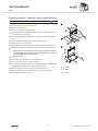
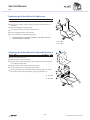
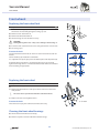
Service Manual Service Manual Table of contents General.......................................................................................................................... 4 Introduction 4 Spare parts 4 Fastening with hexagon socket bolts 4 Visual check 5 Identifying and repairing faults 5 Frame............................................................................................................................. 6 Adjusting the frame 6 Changing the frame 6 Seat................................................................................................................................ 7 Adjusting the seat height 7 Replacing the seat cover 7 Backrest......................................................................................................................... 8 Adjusting the backrest height 8 Backrest angle 8 Tipping point of the wheelchair 8 Replacing the Standard Light backrest cover 8 Replacing Velcro® tapes for adjustable backrests 9 Replacing push handles with Light cover 10 Replacing push handles with adjustable backrest 10 Foldable backrest, angle adjustable (optional) 11 Footrests..................................................................................................................... 12 Replacing the footrest 12 Adjusting the height of the footrest 12 Adjusting the angle of the footrest 12 Sides............................................................................................................................ 13 Fitting the clothes guard 13 Fitting the mudguard 13 Front wheels................................................................................................................ 14 Replacing the front wheel fork 14 Replacing the front wheel 14 Cleaning the front wheel bearings 14 Rear wheels................................................................................................................. 15 Checking the tyre pressure 15 Checking the spoke tension 15 Checking that removable axles are seated correctly 15 Adjusting the removable axles 15 Replacing the rear wheels 16 Replacing the axle 16 Ensuring the rear wheels are parallel 16 Repairing or changing an inner tube 16 Fitting tubed tyres to carbon wheels 17 Brakes.......................................................................................................................... 18 Fitting / adjusting the parking brake 18 Options & accessories................................................................................................ 19 Fitting an antitipper 19 3 © Küschall AG, Switzerland | 2011-12 Service Manual General Introduction This Service Manual contains all the technical information necessary for the inspection, configuration or repair of a Küschall® wheelchair. To maintain the necessary levels of safety and reliability, every wheelchair must be thoroughly examined once a year. Some aspects of the assembly and configuration of the wheelchair require a high level of expertise. These assembly instructions therefore break the various tasks down into 3 categories: Requirement Symbol Easy – technical understanding required Medium – technical knowledge required Difficult – technical knowledge and expertise in assembling wheelchairs required The required tools and their respective sizes are listed above each instruction. The instructions include information on the torques with which the respective screw connections must be tightened. Adhering to the given torques requires the use of a torque spanner. Tools Symbol Allen key à 3, 4, 5 Phillips screwdriver Ò2 Straddle spanner Socket spanner/ring spanner 10, 11, 19 8, 10 Spare parts All spare parts can be purchased from Küschall®'s Customer Services. An electronic spare parts catalog is available by logging onto www.kueschall.com. Only original spare parts may be used. Installing additional adaptations to a Küschall® wheelchair requires the prior written approval of Küschall® AG. Fastening with hexagon socket bolts Hexagon socket bolts are not designed to withstand an excessive application of force. When tightening or undoing a hexagon socket bolt, force must be applied to the nut wherever possible to avoid damaging the bolt. Tightening and undoing Turn the nut using an open-end spanner, or preferably a socket span- ner, using the Allen key simply to stop the bolt turning. Tightening and undoing when no nut is present If a hexagon socket bolt is screwed directly into a thread, the bolt must be tightened using the Allen key. Ensure that the Allen key is of good quality i and not worn. 4 © Küschall AG, Switzerland | 2011-12 Service Manual Torque All screw connections must be tightened with the torques specified in the following instructions. Adhering to the given torques requires the use of a torque spanner. Checks Check that all bolts have been tightened with the torque specified in the instructions. Check the entire frame for cracks, especially in the vicinity of joints and weld seams (frame, axle clamp components, backrest) Several bolts are secured with adhesive. If these are loosened, they j have to be cleaned and secured with adhesive again. Self-locking nuts and screws, once loosened, have to be replaced by j new ones. Identifying and repairing faults Fault The wheelchair does not travel in a straight line The wheelchair tips too easily Removable axles cannot be inserted correctly The brakes are gripping poorly or asymmetrically The rolling resistance is very high Possible cause Action Incorrect tyre pressure on one rear wheel Correct tyre pressure One or more spokes broken Replace broken spoke(s) Spokes tightened unevenly Tighten loose spokes Frame geometry does not meet specifications Fitting an antitipper Backrest angle too great Replace backrest with smaller backrest angle Removable axles dirty Clean removable axles Removable axles misaligned Adjust removable axles Incorrect tyre pressure in one or both rear tyres Correct tyre pressure Tyre pressure in rear tyres is too low Correct tyre pressure Rear wheels not parallel Ensure rear wheels are parallel The front wheels wobble when Too little tension in front wheel bearing block moving fast Front wheel has worn smooth Tighten the nut on the bearing block axle slightly The front wheel is stiff or stuck Clean or replace the bearings Bearings are dirty or faulty 5 Change front wheel © Küschall AG, Switzerland | 2011-12 Service Manual Frame Frame Adjusting the frame The seat width, seat depth, lower leg length and tipping point are determined by the design of the frame and cannot be changed retrospectively. A modification of the tip behaviour can only be achieved by ordering a new, one-off backrest. The seat depth can be adjusted by changing the hole position. Changing the frame Please contact the Küschall® customer service department if you wish to change the frame. 6 © Küschall AG, Switzerland | 2011-12 Service Manual Seat Seat Adjusting the seat height The seat height can only be adjusted by fitting a larger or smaller rear wheel and at the same time using a larger or smaller front wheel fork. Possible front seat heights: SHv [mm] 450 - 510 As the seat angle is dictated by the design of the frame, the seat height rear (SHh) also changes by 10 mm. The following settings are possible: 90° 75° B 3'' 24'' 25'' A C D 4'' E 5'' To ensure that the frame is straight and the axles of the front i wheel forks are perpendicular to the ground, choose one of the combinations listed in the table. Front seat height (SHv) according to front wheel and rear wheel SHv [mm] 450 - 500 460 - 510 possible SHh Rear wheel Frame [mm] 400 - 480 400 - 480 24‘‘ 25‘‘ Front wheel 3'' 4'' 5'' 75° D C B 90° 75° B A -- E D C 90° C B -- Replacing the seat cover Difficulty: Tools: à 3,4, 5 8, 10 0 Remove mudguard or clothes guard by loosening bolts . 0 Remove bolts on both sides of the seat cover. Remove seat cover and replace with new one. Owing to the tension inherent in the design of the frame, it may not i be possible to fit the seat cover. In this case the axle holders must be undone. 1 0 Undo axle holders 3 0 Fit new seat cover using bolts . 0 Ensure the rear wheels are parallel, Chap. Rear Wheels, ‹Ensuring the rear wheels are parallel›, and tighten axle holder bolts. 0 Fit mudguard or clothes guard using bolts . 1 2 à 7 Nm à 4 Nm 7 © Küschall AG, Switzerland | 2011-12 Service Manual Back Backrest Adjusting the backrest height Readjusting the push handle/telescopic tube Difficulty: Tools: Ã3 8 Remove the backrest padding. Remove the screw connection and adjust the desired height of the push handle or the telescopic tube. Insert the screw connection again and tighten the nut. Carry out the same setting on both sides. Refit the backrest padding. 1 If the desired height cannot be achieved, you must use a different i telescopic tube or push handle. If the backrest height is too high, the backrest tube can be cut off and redrilled. Possible backrest heights: RH [mm] 270 285 300 315 330 345 360 375 à 7 Nm 390 Backrest angle If you want to change the backrest angle, then the complete backrest will have to be replaced. Possible backrest angles: RW 74° i 78° 82° 86° 90° Changing the backrest angle also modifies the tipping point of the wheelchair. Tipping point of the wheelchair The tipping point of the wheelchair can only be modified by fitting a new backrest with a larger or smaller backrest angle. The seat depth can also be adjusted by changing the hole position. Replacing the Standard Light backrest cover Difficulty: Tools: à 3 8Ò2 Remove push handles, if fitted, Chap. Back, ‹Replacing push handles›. Remove bolts and , clothes guard or mudguard. Open the Velcro® fastener on both sides. 1 Pull the backrest cover up and off and slip the new backrest cover over the backrest tubes. 2 Close the Velcro® fasteners again on both sides. Fit mudguard or clothes guard. 3 Fit push handles, if required. à 7 Nm à 7 Nm 8 © Küschall AG, Switzerland | 2011-12 Service Manual Back Replacing Velcro® tapes for adjustable backrests Difficulty: Tools: à 3,4, 5 8, 10 Ò2 The upper backrest bands can be taken straight off, the backrest must be removed in order to access the lower ones. 2 0 Remove backrest cover. 1 Remove mudguard or clothes guard. 1 0 Push the backrest band down in order to access the bolts . Remove nuts and bolts on both sides. 0 Pull the push handle and end band out of the backrest tube (if fitted). Pull the upper backrest band off the backrest tube . 5 0 Remove bolts on both sides. 0 Remove the seat cover, the bolts on both sides and the backrest. 0 Replace the lower backrest band and put the backrest to one side. 3 i Owing to the tension inherent in the design of the frame, it may be extremely difficult to reposition the backrest in the frame. In this case the axle holders must also be undone. 4 7 0 Undo axle holders 6 0 Insert the new backrest and secure using bolts . 0 Fit the seat cover, insert and tighten bolts . 0 Ensure the rear wheels are parallel, Chap. Rear wheels, ‹Ensuring the rear wheels are parallel› and tighten axle holder bolts. 0 Pull the upper backrest band over the backrest tube . 0 Refit the push handles and end band and secure using bolts . 0 Fit mudguard or clothes guard. 9 à 7 Nm à 4 Nm à 7 Nm © Küschall AG, Switzerland | 2011-12 Service Manual Back Replacing push handles with Light cover Difficulty: Tools: à 3, 4 Ò2 8 0 Remove bolts on both sides. 0 Push the cover down a little to expose the bolt . Remove bolts on both sides. 1 2 0 Remove mudguard or clothes guard. 0 Pull out push handle and replace with new one. 0 Insert and tighten bolt on both sides. 0 Fit cover to both push handles using bolt . If a push handle is not going to be fitted, a new Light cover that is i sealed at the top can be used. à 4 Nm à 7 Nm Replacing push handles with adjustable backrest Difficulty: Tools: à 3,4 1 8 Ò2 0 Remove backrest cover . 0 Remove bolts and end band . 0 Push the backrest band down a little to expose the bolt . Remove nut and bolt on both sides. 0 Pull the push handles from the backrest tubes. 0 Slip the end band over the new push handles. 0 Fit the push handles in the desired position using the bolts . Secure the end band to the push handles again using the bolts . 2 3 5 6 à 4 Nm à 7 Nm 10 4 © Küschall AG, Switzerland | 2011-12 Service Manual Back Foldable backrest, angle adjustable (optional) Optionally, a foldable, angle-adjustable backrest can be fitted. j For assembling a special Küschall training is necessary. When switching to the foldable backrest, the axle of the rear wheels i must also be replaced with a new one that is 2 cm wider, Chap. Rear wheels, ‹Replacing the axle›. Pre-assembling the foldable backrest Schwierigkeit: Werkzeug: à 3, 4, 5 4 8, 10 1 Push the back band onto the back tubes. Fit the end plugs into the backrest tubes on both sides. 3 Mount the backrest joint plates on both backrest tubes. 3 Fit the backrest angle adjustor through the back band on both backrest tubes facing forwards or backwards, Chap. Back, ‹Backrest angle›. 2 Fitting a foldable, angle-adjustable backrest Schwierigkeit: Werkzeug: à 3, 4, 5 drill, rill bit: ø6.1 8, 10 4 Remove mudguard or clothes guard from both sides. 3 2 Remove the seat cover. 6 Remove old backrest. 1 1 Drill a new hole in the frame, on both sides, with ø 6.1 mm bit, at a distance of 203 mm from the rearmost hole . Re-fit the seat cover. 5 Push the seat tube into the frame on both sides and secure with à 9 Nm bolt . Fit end plugs into end of both seat tubes . both sides with bolt . à 9 Nm 9 Push the pre-assembled backrest onto seat tubes and secure on à 9 Nm 8 à 9 Nm Secure support plate using bolt through the seat cover. 12 Secure support plate using bolt (spacer, plastic washer, washer if required, bolt) and plastic washer in the required adjustor position, Chap. Back, ‹Backrest angle›. On both support plates, pull the strap through hole a and make a knot at both ends. Position the mudguard or clothes-guard on the support plate and drill at position b. Screw the mudguard or clothes-guard onto the support plate 11 7 10 (7 Nm). Backrest angle The backrest angle adjustor can be fitted ‹facing forwards› or ‹facing backwards›: 1 Fitted ‹facing forwards› for seat angles 82, 86 and 90°. Fitted ‹facing backwards› for seat angles 74 and 78°. 11 © Küschall AG, Switzerland | 2011-12 Service Manual Footrests Footrests Three types of footrest are available: A footrest in aluminium or titanium and a footrest with an adjustable footplate. The titanium footrest requires a different sleeve in order to secure it i in the frame. Replacing the footrest Difficulty: Tools: à 4 8 0 Remove bolts on both sides. 1 2 0 Pull out footrest and replace with new one. 0 Insert the bolts through the frame and into the nearest holes at the same height on both sides and tighten them. à 7 Nm Adjusting the height of the footrest Difficulty: Tools: à 4 8 The footrest can be adjusted in 10 mm steps. 0 Remove bolts on both sides. 0 Move the footrest to the required height. 1 0 Insert the bolts through the frame and into the nearest holes at the same height on both sides and tighten them. . à 7 Nm Adjusting the angle of the footrest Difficulty: Tools: à 3 10 For option angle adjustable only. 0 Undo the four bolts so that the footplate can be moved. 1 0 Move the footplate to the required angle and tighten the bolted connections again. The bolts must be tightened very securely to prevent the footplate i from moving. 12 à 13 Nm © Küschall AG, Switzerland | 2011-12 Service Manual Sides Sides Fitting the clothes guard Difficulty: Tools: à 5 8, drill, drill bit: ø5,2 The clothes guard is customised to fit the geometry of the individual i wheelchair. It must therefore only be replaced by another clothes guard of the same size. Remove bolts and and the old clothes guard . Use the old clothes guard as a template by placing it on the new one and marking the position of the holes. Drill holes in the new clothes guard. 2 1 Fit clothes guard using bolts and . 3 à 7 Nm à 7 Nm Fitting the mudguard Difficulty: Tools: à 5 8, drill, drill bit: ø5,2 The mudguard is customised to fit the geometry of the individual i wheelchair. It must therefore only be replaced by another mudguard of the same size. Remove bolts and and the old mudguard . Use the old mudguard from the other side as a template by placing it on the new one and marking the position of the holes. Drill holes in the new mudguard. 2 1 3 Fit mudguard using bolts and . à 7 Nm à 7 Nm 13 © Küschall AG, Switzerland | 2011-12 Service Manual Front wheels Front wheels Replacing the front wheel fork Difficulty: Tools: 1 2 5 10 4 Remove the sealing cap . Do this by inserting two screwdrivers into the notches and carefully prising the sealing cap out. Remove nut and washer . Remove the front wheel fork . 4 Check bearings and renew if necessary. 3 CAUTION! Overtightening of the nuts may cause damage to the bearings . j Insert the new castor fork and secure it using the washer and nut . Fit sealing cap . Functional check Tip the wheelchair backwards 90° so that it rests on the backrest and rear wheels. A Turn the fork up (A) and allow it to fall down. It is adjusted correctly if it just passes the lowest point and stops there (B). If the fork moves back when in its lowest position (C), it has not been tightened enough. There is a risk that the front wheels will start to wobble when travelling at high speeds. B C Replacing the front wheel Tools: à 2x3 Difficulty: 1 Remove bolts , pull out wheel axle . 2 Remove the front wheel and replace with a new one or move to a new position. i Two extra sleeves per wheel are fitted for some front wheels. 2 3 Replace the axle and tighten bolt . 1 4 3 Functional check There must be no play in the wheel but it must turn easily. 4 à 4 Nm 1 Cleaning the front wheel bearings 0 Check that the front wheels turn freely. 0 Remove any dirt or hair from the front wheel bearings. 14 © Küschall AG, Switzerland | 2011-12 Service Manual Rear wheels Rear wheels Checking the tyre pressure Tyre Max. pressure Low-resistance tyre 7 bar 700 kPa 101 psi Treaded tyre (marathon) 7.5 bar 750 kPa 108 psi Slick tyres (speed run) 10 bar 1000 kPa 145 psi Mountain bike tyre 4 bar 400 kPa 58 psi Tubed tyre, carbon wheel 14 bar 1400 kPa 202 psi 0 Measure the tyre pressure. 0 Inflate the tyres to the required pressure. 0 Check the tyre tread. Change the tyres if necessary. The air pressure in tubed tyres on carbon wheels must be not less i than 10 bar in order to prevent damage to the carbon rim. Checking the spoke tension The spokes may not be loose or distorted. 0 Tighten any loose spokes with a suitable spoke spanner. 0 Replace broken or distorted spokes and check that the wheel is running true. Checking that removable axles are seated correctly 0 To check that a removable axle is seated correctly, grasp the rear wheel by the hub and try to pull it off. You should not be able to pull it off and it must only exhibit a very small amount of play. 0 If the rear wheels are not engaged properly, remove any dirt or deposits. If the problem persists, adjust the removable axles. Adjusting the removable axles Difficulty: Tools: 11, 19 0 Remove the rear wheel, adjust the removable axle slightly using two spanners and replace. If there is too much play, shorten length L a little. If the removable axle does not engage properly, extend the length L. The adjustment must be carried out on both wheels. When neither i removable axle exhibits any play, fit the wheels on the other side of the wheelchair. The axles are adjusted correctly if one of them now exhibits a small amount of play. 15 © Küschall AG, Switzerland | 2011-12 Service Manual Rear wheels Replacing the rear wheels Difficulty: Proceed as follows if the rear wheels are replaced by ones of a different size or with other tyres: 0 Check function of the parking brakes. 0 Adjust seat height, Chap. Seat, ‹Adjusting the seat height› 0 Check that the mudguard or clothes guard is positioned correctly. Replacing the axle Difficulty: Tools: à 5 22 Remove the wheels and unscrew bolts on both axle clamp components. Remove both axle clamp components and the axle. Insert new axle, re-attach the axle clamp components and bolts . Tighten the bolts only slightly. Ensure the wheels are parallel, Chap. Rear wheels, ‹Ensuring the rear wheels are parallel›. Ensuring the rear wheels are parallel Difficulty: Tools: à 5 22 The wheelchair will have ideal straight-line stability when the rear wheels are exactly parallel to one another. Place the wheelchair on a flat, even surface. Undo the bolts on the two axle clamp components. At the level of the axle, measure the distance between the wheels at the front (y) and back (x): The distance at the front (y) must be precisely the same or up to 2 mm greater than the distance at the back (x). This difference evens itself out when someone sits in the wheelchair. 1 Once the wheels are aligned tighten bolts . Check that the wheels are parallel once again. à 9 Nm 0 Check that the parking brakes are positioned and adjusted correctly. Repairing or changing an inner tube Difficulty: Tool: tyre lever 0 Remove the rear wheel and release any air from the inner tube. 0 Lift one tyre wall away from the rim using a bicycle tyre lever. Do not use sharp objects such as a screwdriver which could damage the inner tube. 0 Pull the inner tube out of the tyre 0 Repair the inner tube using a bicycle repair kit or, if necessary, replace the tube. 0 Inflate the tube slightly until it becomes round. 0 Insert the valve into the valve hole on the rim and place the tube inside the tyre (the tube must lie right round the tyre with no creases). 0 Starting close to the valve, push the tyre wall over the edge of the rim using both hands. When doing this, check all the way round to ensure that the inner tube is not trapped between the tyre and the rim. 0 Inflate the tube to its maximum operating pressure, Table, chap. Rear wheels, ‹Checking the tyre pressure›. Check that no air is escaping from the tyre. 16 © Küschall AG, Switzerland | 2011-12 Service Manual Rear wheels Fitting tubed tyres to carbon wheels Difficulty: Tubed tyres must be attached to the rim using a special adhesive! i Carry out a test fitting first without using any adhesive. 0 Check the valve length, insert extension if necessary. Recommendation: inflate the tyres slightly before putting them on the rim. This makes them easier to mount. 0 Apply an even coating of adhesive to the protective strip on the tyres and allow to dry for at least 6 hours. (3) If you have a new rim 0 Degrease the rim and roughen its base with fine sandpaper if required (1). 0 Apply an even coating of adhesive to the rim (2) and allow to dry for at least 6 hours. If you have a used rim 0 Check the existing layer of adhesive. An even and intact adhesive layer can still be used. If the layer is very uneven, remove all adhesive from the rim and apply a fresh layer of adhesive. 0 Apply a fresh layer of adhesive to the rim (2) and mount the tyre immediately. 0 Mount the tyre. Insert the valve. Pull the tyre down forcefully so that the final part of the tyre can be lifted easily and in a controlled manner over the edge of the rim (4-7). 0 Inflate the tyre a little and ensure it is centred. The edge of the protective seam strip (8) can be used as a guide. 0 Inflate the tyre to about 9 bar and use your full body weight to press it on all round. Clean any excess adhesive from the braking surfaces of the rim. 0 Important: Keep under pressure for 24 hours! Check tyre frequently. Never use tyres that have a damaged or loose protective strip. j 17 © Küschall AG, Switzerland | 2011-12 Service Manual Brakes Brakes Fitting / adjusting the parking brake Tools: à 5 Difficulty: 2 Following each positioning, the rear wheel parking brakes (e.g. when j changing the wheel chamber) must be readjusted. The parking brake function is only guaranteed if the tire has the j corresponding air pressure. Check that the rear wheels have sufficient air. 1 2 3 1 Loosely fix the clamping piece to the frame with the screw . 2 Slide the brake into the correct position and tighten the screw . à 13 Nm 4 When the brake is on, the brake shoe must press approx. 4 mm into the tire. i Furthermore, please note that very little force is required for i activating and deactivating the brake. If necessary, a brake lever extension can be fitted. Visual check Check that the parking brake is correctly positioned. The brake is correctly adjusted if the brake shoe does not press more than 4 mm into the tire when the brake is on. Function check Place the loaded wheelchair on a ramp with a 7° slope with the parking brake on. The wheelchair must not move. Carry out this check with the wheelchair both facing down the ramp and facing up the ramp. 18 © Küschall AG, Switzerland | 2011-12 Service Manual Options & accessories Options & accessories Fitting an antitipper Tools: à 5 Difficulty: 1 Undo bolt and remove the lower part of the axle holder. 2 Secure the adapter bracket with a bolt and apply a low-strength 2 adhesive (e.g. Loctite 243). 1 0 Fit antitipper to adapter bracket . Tighten bolts . Setting the height 0 Push in adjusting knob and pull the antitipper tube to the required position. Allow the adjusting knob to latch into one of the holes. Measure the distance to the ground; it must be between 40 and 60 mm. 3 à 9 Nm à 9 Nm 5 1 4 Function check: The antitipper must be able to swing underneath the wheelchair without any difficulty. The distance between the antitipper and the ground must be 40-60 mm. It must be easy to fold up the antitipper. Tip the wheelchair backwards using the antitipper until the axle is perpendicular to the antitipper’s point of contact with the ground. In this position, the distance between the rear wheel and the ground must be at least 50 mm. x x 50 mm 19 © Küschall AG, Switzerland | 2011-12 Küschall AG Benkenstrasse 260 CH-4108 Witterswil [email protected] www.kueschall.com Service Manual Ksl ENGLISH | 2011-12 küschall® distributors Belgium & Luxemburg: Invacare nv • Autobaan 22 • B-8210 Loppem Tel: (32) (0)50 83 10 10 • Fax: (32) (0)50 83 10 11 • [email protected] Danmark: Invacare A/S • Sdr. Ringvej 37 • DK-2605 Brøndby Tel: (45) (0)36 90 00 00 • Fax: (45) (0)36 90 00 01 • [email protected] Deutschland: Invacare GmbH • Alemannenstraße 10 • D-88316 Isny Tel: (49) (0)75 62 7 00 0 • Fax: (49) (0)75 62 7 00 66 • [email protected] Deutschland: Ulrich Alber GmbH • Vor dem Weissen Stein 21 • D-72461 Albstadt-Tailfingen Tel: (49) (0)74 32 2006 0 • Fax: (49) (0) 74 32 2006 299 • [email protected] European Distributor Organisation: Invacare • Kleiststraße 49 • D-32457 Porta Westfalica Tel: (49) (0)57 31 754 540 • Fax: (49) (0)57 31 754 541 • [email protected] España: Invacare SA • c/Areny s/n • Polígon Industrial de Celrà • E-17460 Celrà (Girona) Tel: (34) (0)972 49 32 00 • Fax: (34) (0)972 49 32 20 • [email protected] France: Invacare Poirier SAS • Route de St Roch • F-37230 Fondettes Tel: (33) (0)2 47 62 64 66 • Fax: (33) (0)2 47 42 12 24 • [email protected] Ireland: Invacare Ireland Ltd • Unit 5 Seatown Business Campus • Seatown Road • Swords • County Dublin – Ireland Tel : (353) 1 810 7084 • Fax: (353) 1 810 7085 • [email protected] Italia: Invacare Mecc San s.r.l. • Via dei Pini 62 • I-36016 Thiene (VI) Tel: (39) 0445 38 00 59 • Fax: (39) 0445 38 00 34 • [email protected] Nederland: Invacare BV • Celsiusstraat 46 • NL-6716 BZ Ede Tel: (31) (0)318 695 757 • Fax: (31) (0)318 695 758 • [email protected] • [email protected] Norge: Invacare AS • Grensesvingen 9 • Postboks 6230 • Etterstad • N-0603 Oslo Tel: (47) (0)22 57 95 00 • Fax: (47) (0)22 57 95 01 • [email protected] • [email protected] Österreich: Invacare Austria GmbH • Herzog Odilostrasse 101 • A-5310 Mondsee Tel.: (43) 6232 5535 0 • Fax.: (43) 6232 5535 4 • [email protected] Portugal: Invacare Lda • Rua Estrada Velha • 949 • P-4465-784 Leça do Balio Tel: (351) (0)225 1059 46/47 • Fax: (351) (0)225 1057 39 • [email protected] Sverige & Suomi: Invacare AB • Fagerstagatan 9 • S-163 91 Spånga Tel: (46) (0)8 761 70 90 • Fax: (46) (0)8 761 81 08 • [email protected] • [email protected] Switzerland: Invacare AG • Benkenstrasse 260 • CH-4108 Witterswil Tel.: (41) (0)61 487 70 80 • Fax.: (41) (0)61 487 70 81 • [email protected] United Kingdom: Invacare Limited • Pencoed Technology Park, Pencoed, Bridgend CF35 5AQ • Switchboard Tel: (44) (0)1656 776 200, Fax: (44) (0)1656 776 201 • Customer services Tel: (44) (0) 1656 776 222 • Fax: (44) (0) 1656 776 220 © Küschall AG, Schweiz | 2011-12