1
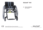
KÜSCHALL K-SERIES attract DEALER: Keep this manual. The procedures in this manual MUST be performed by a qualified technician. Service Manual ©2014 Küschall AG All rights reserved. Republication, duplication or modification in whole or in part is prohibited without prior written permission from Küschall AG. Trademarks are identified by ™and ®. All trademarks are owned by or licensed to Küschall AG or its subsidiaries unless otherwise noted. Service Manual KÜSCHALL K-SERIES attract TABLE OF CONTENTS GENERAL....................................................................................................................... 4 Introduction 4 Spare parts and adaptations 4 Tightening Allen screws 4 Torque 5 Checks 5 Identifying and alleviating malfunctions 5 OVERVIEW.....................................................................................................................6 Components 6 Dimensions 6 FRAME.............................................................................................................................7 SEAT............................................................................................................................... 8 Seat width (SB) 8 Seat depth (ST) 8 Front seat height (SHv) 8 Rear seat height (SHh) 10 Seat angle (SW) 10 Tipping point adjustment 11 BACKREST....................................................................................................................12 Backrest height (RH) 13 Adjusting the backrest height 13 Securing/adjusting the release cord 13 Replacing the backrest tube 14 Replacing the handle 15 Replacing foldable push handles 15 Backrest angle (RW) 16 FOOTRESTS ................................................................................................................17 Lower leg length (UL) 17 Replacing footrests 17 Adjusting the footrest height 17 Angle-adjustable footplate, adjusting the angle 17 SIDE PARTS..................................................................................................................18 Clothes-guard/mudguard 19 FRONT WHEELS..........................................................................................................21 Replacing a front wheel 21 Replacing a front wheel fork 21 REAR WHEELS............................................................................................................ 22 Ensuring the rear wheels are parallel 22 Adjusting the removable axle 22 Changing the wheel chamber 22 BRAKES........................................................................................................................ 23 Fitting / adjusting the parking brake 23 OPTIONS & ACCESSORIES....................................................................................... 24 Antitipper 24 Fitting the pelvic belt 25 Attaching the snap hook symbols 25 3 © Küschall AG, Switzerland | 2014-12 Service Manual KÜSCHALL K-SERIES attract GENERAL Introduction This service manual is part of the instructions and contains the technical information for servicing, configuring and repairing a küschall® wheelchair. WARNING! Danger of accident and severe injuries. If the wheelchair is improperly set it can cause accidents and severe injuries. ▸▸Changes to the wheelchair may only be carried out by the provider. To guarantee the required safety and reliability, all wheelchairs must be comprehensively checked once a year. In part, assembly and adjustment require extensive experience. For this reason, the following assembly instructions have been split into three categories: Requirement Symbol Easy – technical understanding required Intermediate – specialist knowledge required Difficult – specialist wheelchair assembly knowledge and experience required The required tools and their respective sizes are listed above each instruction. The instructions include information on the torques with which the respective screw connections must be tightened. Adhering to the given torques requires the use of a torque spanner. Tools Symbol Allen key à 3, 4, 5 Phillips screwdriver Ò2 Straddle spanner Socket spanner/ring spanner 10, 11, 19 8, 10 Spare parts and adaptations All spare parts can be purchased from küschall®'s Customer Services. An electronic spare parts catalog is available by logging onto www. kuschall.com. Only original spare parts may be used. Installing additional adaptations to a küschall® wheelchair requires the prior written approval of Küschall AG. Tightening Allen screws Allen keys are not designed for greater forces. When tightening or loosening an Allen screw, it is therefore advisable to apply force to the nut to prevent the hexagon socket from being damaged. Tightening and loosening Turn the nut with a socket spanner (only use a straddle spanner if there is insufficient space) and merely hold the screw tight with the Allen key. 4 © Küschall AG, Switzerland | 2014-12 Service Manual KÜSCHALL K-SERIES attract Tightening and loosening if there is no nut If an Allen screw is directly screwed into a screw thread, the screw must be tightened using an Allen key. i and not worn. Ensure that the Allen key is of good quality Torque All screw connections must be tightened with the torques specified in the following instructions. Checks Visual check Check all components for cracks, especially the areas around joints and welded seams. Checking the screw connections Check all bolts with the torques specified in the instructions regularly, and adjust if required. CAUTION! Several screw connections have been secured with thread locking adhesive. If these are opened, they must be secured again using new thread locking adhesive. High-strength and low-strength adhesives are available. For torque entries notice shall be made whether an adhesive and which adhesive needs to be used. Identifying and alleviating malfunctions Malfunction The wheelchair will not move in a straight line The wheelchair tips backwards too easily The brakes engage poorly or asymmetrically Roll resistance is too great The front wheels wobble when moving fast The front wheel is stiff or stuck Increased forward tip tendency Possible cause Measure Incorrect tire pressure in a rear wheel One or more spokes broken Spoke unevenly tensioned Dirty or damaged wheel bearings Rear wheels have been fitted too far forward Backrest angle too great Seat angle too great Incorrect tire pressure in one or both rear wheels Brake setting incorrect Insufficient tire pressure in the rear wheels Rear wheels are not parallel Correct tire pressure Replace defective spoke(s) Tighten excessively loose spokes Clean or replace bearings Fit rear wheels further back Reduce backrest angle Use longer vertical struts Correct tire pressure Correct brake setting Correct tire pressure Ensure that the rear wheels are parallel Lightly tighten the nut in the bearings Insufficient tension in the front wheel bearings block block axle Front wheel is worn flat Replace front wheel Dirty or damaged bearings Clean or replace the bearings Frame deformed Replace frame 5 © Küschall AG, Switzerland | 2014-12 Service Manual KÜSCHALL K-SERIES attract OVERVIEW OVERVIEW Components A Backrest B Rear wheel with handrim C Quick release axle D Folding mechanism E Front wheel fork with front wheel F Footrest G Frame H Seat I Mudguard Dimensions A Seat depth 375 – 475 mm, in increments of 25 mm) B Backrest angle 74°/78°/82°/86°/90° C Knee-to-heel length 400 – 480 mm, in increments of 10 mm D Seat height front 480 – 510 mm, in increments of 10 mm E Seat height rear 400 – 480 mm, in increments of 10 mm F Backrest height 315 – 480 mm, in increments of 15 mm G Total length 75°: approx. 830 mm H Seat width 90°: approx. 760 mm 6 Seat width + 170 mm © Küschall AG, Switzerland | 2014-12 Service Manual KÜSCHALL K-SERIES attract FRAME FRAME The küschall K-Seriesattract frame is available in aluminium. Aluminium frames come with frame angles of 75° and 90°. Alu Frame Front seat height (SHv) in mm (with a 24” rear wheel) Lower leg length (UL) with standardmounted bar* Seat depth (ST) 75° standard 480 to 510 SHv -110 to SHv -30 375 to 475 90° standard 480 to 510 SHv -130 to SHv -40 375 to 475 *For lower leg lengths, the high-mounted footrest must be used. Chapter: Footrests, "Assembling and adjusting high-mounted footrests" 7 © Küschall AG, Switzerland | 2014-12 Service Manual KÜSCHALL K-SERIES attract SEAT SEAT Seat width (SB) Available seat widths: SB 360 to 480 in 20 mm steps. Changing the seat width is very complicated and requires the replacement of numerous parts. Seat depth (ST) Available seat depths: ST 375 to 475 in 25 mm steps. Changing the seat depth requires the replacement of the seat rails, the seat cover and potentially also the seat cushion. Front seat height (SHv) The front seat height is dependent on several factors that interact with each other. The size of the rear wheels determines the height of the sub-structure. In addition to the positioning of the brackets on the seat module, the frame, seat depth and rear seat height influence the seat height. 90° 75° A B 5“ 4“ Possible front and rear wheel combinations Rear wheel Frame 24" 4'' 5'' 75° A A 90° B - i wheel supports are perpendicular to the ground. Only select combinations listed in the Table to ensure that the frame is straight and the front 8 © Küschall AG, Switzerland | 2014-12 Service Manual KÜSCHALL K-SERIES attract SEAT If the rear wheel, front wheel and front wheel fork are defined, the front seat height can be adjusted by changing the position of the seat module within the frame. There is 1 bracket available with 8 fixing options. 1 2 3 4 5 6 7 8 Positioning or replacing the brackets at the front for setting the front seat height (SHv) Difficulty: Tools: à 4, 5 Remove the rear wheels, fold the backrest forward and place the wheelchair on its back. Remove all screws on one side that hold the seat cover to remove tension. Loosen the screws A and B that connect the seat brace C to the A à 7 Nm B à 13 Nm E à 7 Nm F à 7 Nm seat module or the frame on both sides. Remove the screw E and place it in the bracket’s D other hole. Refit the rear wheels, stand the wheelchair back up and check the position of the seat braces C. They must be as perpendicular to the ground as possible. Reattach the seat cover and tighten the screws. Tighten the screw connections A and B of the seat braces and E and F of the front brackets again. Carry out the same setting on both sides. i results in a change to the seat angle. It may be Note: ensure that adjusting the front seat height necessary to correspondingly adjust the rear seat height (SHh) or the backrest angle. 9 © Küschall AG, Switzerland | 2014-12 Service Manual KÜSCHALL K-SERIES attract SEAT Rear seat height (SHh) The seat braces can be repositioned to adjust the rear seat height. Generally, we recommend fixing the seat braces to the hole A on the frame. Following table serves as an example, the positions can vary. Rear seat height based on wheel position 1 2 SHh Hole combination 400 A1 4 410 A2 5 420 A3 6 430 A4 7 3 440 A5 450 A6 460 A7 A 470 B7 B 480 C7 C Adjusting the rear seat height (SHh) Tools: à 5 Difficulty: Remove the rear wheels, fold the backrest forward and place the wheelchair on its back. Remove all screws on one side that hold the seat cover to remove tension. Loosen the screw A for the front bracket on both sides. Loosen the screw C and remove the screws D and the connecting bar E. Carry out the same setting on both sides. Slide the seat brace against the rear bracket so that the required holes overlap. A à 7 Nm Insert the connecting bar E and fix it with screw D. C à 13 Nm Refit the rear wheels, stand the wheelchair D à 7 Nm back up and check the position of the seat brace C. It must be as perpendicular to the ground as possible. Reattach the seat cover and tighten the screws. Tighten the screws A, C and D. i to the seat angle. It may be necessary to correspondingly adjust Note: ensure that adjusting the rear seat height results in a change the front seat height (SHv) or the backrest angle. Seat angle (SW) The seat angle is determined by the difference between the rear seat height (SHh) and the front seat height (SHv). 10 © Küschall AG, Switzerland | 2014-12 Service Manual KÜSCHALL K-SERIES attract SEAT Tipping point adjustment The tipping point of the wheelchair can be adjusted by changing the horizontal position of the seat module. Tools: à 4, 5 Difficulty: Remove the rear wheels, fold the backrest forward and place the wheelchair on its back. Remove all screws on one side that hold the seat cover to remove tension. Loosen the screws A, B and E on both sides. Remove the screws C and D and slide the seat module forwards or backwards. Reposition all screws (A, B, C, D and E) but do not tighten them. Reattach the seat cover and tighten the screws. Tighten all screws (A, B, C, D and E) alternately and uniformly on both sides. There are 4 possible positions for the rear bracket and 4 possible positions for the front bracket. Make sure to choose the corresponding position front to back. Note: ensure that the seat brace F is as vertical as possible i following an adjustment. A à 7 Nm B à 7 Nm C à 7 Nm D à 7 Nm E à 13 Nm 11 © Küschall AG, Switzerland | 2014-12 Service Manual KÜSCHALL K-SERIES attract BACKREST BACKREST The adjustable back is fitted with velcro bands and a cover. Apart from the adjustable back there is the light cover, which is produced individually for each backrest height (RH) and seat width (SB). Backrest height (RH) to cover, backrest tube, pushhandles and bands cover backrest tube I pushhandle A telescopic tube straight B bands above stabilizing bar 315 S L S 1-band G 330 S L S 1-band G 345 M L S 1-band G 360 M L S 1-band G 375 M L S 2 x 1-band G 390 M L L 2 x 1-band G 405 M L L 2 x 1-band G 420 L L L 2-bands+1-band 435 L L L 2-bands+1-band 450 L L L 2-bands+1-band 465 L L L 2-bands+1-band 480 L L L 2 x 2-bands H top band backrestband, 10 cm E RH standard pushhandles A foldable pushhandles B * RH 270 only for standard pushhandles Backrest height (RH) to pushhandles, telescopic tubes and bands height adjustable pushhandles, rearset D C bands above stabilizing bar 315 1-band G S 1-band G 330 1-band G S 1-band G 345 1-band G S 1-band G 1-band G 1-band G S 1-band G M 2 x 1-band G 390 2 x 1-band G M 2 x 1-band G 405 2 x 1-band G 420 2 x 1-band G M 2 x 1-band G M 2 x 1-band G 435 2-bands+1-band L 2 x 1-band G 450 465 2-bands+1-band L 2-bands+1-band 2-bands+1-band L 2-bands+1-band 480 2-bands+1-band L 2-bands+1-band endband, 10 cm F 360 375 top band F telescopic tube bended F top band endband, 10 cm F bands above stabilizing bar 10 cm RH 5 cm without pushhandles C A 1-band strap G is placed beneath the stabilizing bar if there is a clothes-guard, and a 2-bands strap H if there is a mudguard. 12 © Küschall AG, Switzerland | 2014-12 Service Manual KÜSCHALL K-SERIES attract BACKREST Backrest height (RH) The height of the backrest can be adjusted by moving the backrest tube. Adjusting the backrest height Readjusting the push handle/telescopic tube Difficulty: Tools: à 3, 8 Remove the backrest padding. Remove the screw connection A and adjust the desired height of the push handle or the telescopic tube. Insert the screw connection A again and tighten the nut. Carry out the same setting on both sides. Refit the backrest padding. i telescopic tube or push handle. If the desired height cannot be achieved, you must use a different A à 7 Nm Securing/adjusting the release cord Difficulty: WARNING! Risk of injury to the user during use as a result of the backrest folding over unintentionally. If the release cord is too taut, the locking mechanism B can open unintentionally. Make sure that the release cord is not too taut. Knot the release cord A, left and right, to the wire rings C such that it is free from tension, but still ensuring that there is only minimal slack (< 5 mm). 13 © Küschall AG, Switzerland | 2014-12 Service Manual KÜSCHALL K-SERIES attract BACKREST Replacing the backrest tube Difficulty: Tools: à 3, 4 8, 10 Remove the backrest padding. Slide the backrest bands upwards or downwards to gain access to the screws A. Remove the screws and nuts on both sides. Remove the push handles or the telescopic tubes and remove the upper Velcro® bands. Remove the screws B on the backrest joint. Remove the lower Velcro® bands and the sleeve D with the adjustment screw E from the backrest tube C and fit both to the new backrest tube. Fit the backrest tube to the backrest joint with the screws B. Here, first fit the lower screw followed by the upper screw. Fit the upper Velcro® bands and the push handles or the telescopic tubes again and fix them with screws A and nuts. Carry out the same setting on both sides. A à 7 Nm B à 7 Nm Refit the backrest padding. F à 7 Nm The excentre plates must be adjusted identically on both sides of the wheelchair, Adjusting the backrest angle. Check: Check the settings of the adjustment screws E on both sides. The screw head must only lightly touch the seat module when the backrest is in the upright position. If necessary, readjust the length by releasing the counter nut and tightening or loosening the adjustment screw. Then retighten the counter nut F. Incorrectly adjusted adjustment screws result in damage to the backrest joint’s mechanism, Adjusting the backrest joint. 14 © Küschall AG, Switzerland | 2014-12 Service Manual KÜSCHALL K-SERIES attract BACKREST Replacing the handle An adhesive (e.g. hair spray) is used in these instructions. When applied to the handle, this substance works as a lubricant and as an adhesive once dry. After drying, the adhesive used must be able to resist a pull-off force of 750 N. If in doubt, contact Küschall® AG. Difficulty: 0 Remove the old handle. 0 Remove any residue (residual adhesive, grease, dust) from the push handle tube. 0 Apply a thin layer of hair spray all over the surface of the push handle tube onto which the handle is to be slid. 0 Apply a thin layer of hair spray to the inside of the handle. 0 Slide the new handle onto the push handle tube. 0 Move the handle into the correct position (grooves facing upwards). i short one, the push handle tube must be shortened by 35 mm. If a long handle has been fitted and this is to be replaced with a The push handle tube must be replaced when switching from a short to a long handle. Replacing foldable push handles Difficulty: Tools: Hole punch pliers 6 mm, à 3, 4 0 Remove the old foldable push handle. 0 Pull down the backrest cover G on the telescopic tube, until its hole B is uncovered. IMPORTANT! Make sure that the threaded insert F (part no. 1580450) supplied with the new push handle is used for assembly. 0 Place the threaded insert F in the telescopic tube. 0 Punch a hole through the backrest cover with a distance of 10 mm from the upper egde, using hole punch pliers (see graphic below). 0 Slide the new foldable push handle A onto the telescopic tube. 0 Fix the foldable push handle with screw C (M5x12). 0 Pull up the backrest cover, until it covers completely the rear hole in the pushhandle. C à 3 Nm (low-strength) D à 7 Nm (low-strength) 0 Fix the foldable push handle with screw D (M5x14) and washer H. 0 Check screws E on both sides of the push handle and re-tighten if necessary. Carry out the same steps for the other push handle. IMPORTANT! Make sure that the folding force is approximately 5 N (0.5 kg). i 10 mm The retrofit of foldable push handles requires new tubing. 15 © Küschall AG, Switzerland | 2014-12 Service Manual KÜSCHALL K-SERIES attract BACKREST Backrest angle (RW) The angle of the backrest can be changed by repositioning the excentre plate in the backrest joint plate. The following angles (measured from the seat) can be set: 82° ° 86 86 ° ° 90 90 ° ° 74 74 ° 82 ° 78 ° ° 78 ° 82 ° 82 ° 74 82 ° 82 ° 78 ° ° ° 74 82 ° 82 ° 78 ° 78 ° 74 90° ° ° 90 90 ° ° 86 86 ° 86 ° 90 ° 82 ° 82 86° 82 78° ° 74° Adjusting the backrest angle Difficulty: Tools: à 3, 10 Fold down the backrest and release the counter nut of the adjustment screw A and screw it in completely. Remove the screw B on the excentre plate C. Remove the excentre plate and reinsert it in the desired position. B à 4 Nm The excentre plates must be set identically on both sides of the wheelchair. E à 7 Nm Reinsert the screw B and tighten it. Fold the backrest up until the stop bolts D engage and unscrew the adjustment screw A until it touches the frame and the backrest joint no longer moves. Tighten the counter nut E. Adjusting the backrest joint Difficulty: Tools: 10 Put the backrest up and let the pin A engage. Press the backrest forwards to ensure the joint cannot move. Unscrew the screw C until it touches the spigot D of the seat frame. Screw the screw back in by between a ¼ and a ½ turn and counter with the counter nut E. Correctly adjust the backrest joint on both sides. E à 7 Nm Function check: Sit in the wheelchair and lean back so that the backrest is strained. Upon pulling the release cord B, the pin A must be easily removed on both sides and must fully glide back in upon letting go of the release cord. 16 © Küschall AG, Switzerland | 2014-12 Service Manual KÜSCHALL K-SERIES attract FOOTRESTS FOOTRESTS The footrest must be selected in accordance with the seat width. A standard footrest and an angle-adjustable footrest are available. Lower leg length (UL) To change the lower leg length, the footrest can be fixed at a higher or lower position. Table, Chap. Frame. The shortest lower leg lengths can be achieved using the high-mounted footrest. ‹Fitting and adjusting high-mounted footrest› Replacing footrests Tools: à 4, Difficulty: 8 Remove the screw connections A on both sides. Remove the footrest and replace it with a new one. Tighten the screw connections A on both sides. Carry out the same setting on both sides. A à 4 Nm Adjusting the footrest height Difficulty: Tools: à 4, 8 The height of the footrest can be adjusted in 10 mm steps. Remove the screw connections A on both sides. Slide the footplate to the desired height. A à 4 Nm Tighten the screw connections A on both sides. Carry out the same setting on both sides. Angle-adjustable footplate, adjusting the angle Difficulty: Tools: à 4, 10 To adjust the angle, release the four screw connections A until the footplate can be moved. A à 13 Nm Check and/or adjust the distance between the left and the right sides by pushing in or pulling out the tubes below the footplate in such a way that the bearings blocks are perpendicular to the ground. Tilt the footplate into the desired position and tighten the screw connections A. The angle of the footplate must be set so that the user’s feet cannot slide off the plate. Make sure that the footplate has a minimum distance of 20 mm to the floor at its lowest point. 17 © Küschall AG, Switzerland | 2014-12 Service Manual KÜSCHALL K-SERIES attract FOOTRESTS Fitting and adjusting high-mounted footrest Difficulty: Tools: à 4, 5 8, 10 Fit the frame bar D for the high-mounted footrest to the front frame on both sides using the screw connections A. Fix the clamp set C to both sides of the frame using the screw connection B. Only tighten lightly. Slide the high-mounted footplate E into the clamp set and to the desired height. Tighten the screw connections B on both sides. A à 7 Nm B à 7 Nm 18 © Küschall AG, Switzerland | 2014-12 Service Manual SIDE PARTS KÜSCHALL K-SERIES attract SIDE PARTS Fitting and adjusting a height-adjustable armrest Difficulty: Tools: à 4, 5, Ò 2 Fit the holder A and the bracket B to the seat module on both sides. Tighten the screws C only lightly. Fit the bar D between the brackets B using screws E. Tighten the screws C. To adjust the armrest height, insert the armrest F into the holder A. Loosen the screws G for the height adjustment and slide it into the desired position. Then retighten the screws G for the height adjustment. By tightening or loosening the screws H, you can adjust how easily the armrest can be pulled out or pushed in. C à 7 Nm E à 7 Nm G à 4 Nm 19 © Küschall AG, Switzerland | 2014-12 Service Manual KÜSCHALL K-SERIES attract SIDE PARTS Clothes-guard/mudguard The clothes-guard fitted as standard can be replaced by a mudguard. Clothesguard and mudguard are available in plastic or in carbon. For the carbon mudguard there is an additional size (XL) for the two smallest rear seat hights (SHh). Clothes-guard size Wheel size SHh 24‘‘ 400 L 410 L 420 L 430 L 440 M 450 M 460 M 470 M 480 M M L Mudguard size plastic Wheel size SHh 24‘‘ 400 L 410 M 420 M 430 M 440 M 450 M 460 M 470 M 480 M L Mudguard size carbon Wheel size SHh 24‘‘ 400 L 410 L 420 L 430 L 440 M 450 M 460 M 470 M 480 M L 20 © Küschall AG, Switzerland | 2014-12 Service Manual SIDE PARTS KÜSCHALL K-SERIES attract Replacing the clothes-guard The mounting element A on the backrest must already be fitted. Difficulty: Tools: à 3, 4 If present, remove the clothes-guard to be replaced by loosening the screw connection C. Check the correct position of the clothes-guard B with fitted rear wheel. Here, find the suitable height on the clothesguard B for fixing the screw connection C to the backrest mount A. If necessary, the holder D on the seat module can be replaced. Here, remove the screw E. i between the seat module and the holder and the upper edge The clothes-guard is correctly positioned if it can be inserted runs above the rear wheel. C à 4 Nm E à 7 Nm F à 4 Nm Fitting the mudguard Difficulty: Tools: à 3, 4, 10 Ò 2 Remove the clothes-guard and the mounting elements on the backrest and the seat. Fit the holder to the seat module using the screw connections A and then refit the rear wheel. 2 Slightly loosen the screws B on the adjustment plate and slide it along the mudguard carrier until the mudguard is at the right height. The position of the mudguard can also be adjusted: Here, loosen the screw connections C and D, position the mudguard as required and tighten the screw connections C and D again. Tighten the screws B again. Carry out the same setting on both sides. By tightening or loosening the screws E you can adjust how easily the armrest can be pulled out or pushed in. i between the mudguard and the wheel must be at least 40 mm. The existing axle may not be sufficiently long for the new i configuration with mudguard. In this case, a longer axle must be If the wheelchair is equipped with a suspension, the distance fitted. Changing the wheel chamber / fitting and adjusting an axle The distance between the mudguard and the wheel must be either < 8 mm or > 25 mm to prevent fingers from becoming caught between the wheel and the mudguard. 21 A à 7 Nm B à 4 Nm C à 7 Nm D à 7 Nm © Küschall AG, Switzerland | 2014-12 Service Manual KÜSCHALL K-SERIES attract FRONT WHEELS FRONT WHEELS Replacing a front wheel Tools: à 2x3 Difficulty: Remove screws A. Remove the wheel axle B. A à 4 Nm Remove the front wheel C. i The bearings are pre-mounted in the front wheel. Slide the axle B through the fork D and the bearings of front wheel C and fix the axle using screws A. Here, use the new screw supplied with the wheel as this screw comes with a thread-locking device. Function check: The wheel may not wobble, but must rotate easily. Replacing a front wheel fork Difficulty: Tools: 10 Remove the sealing cap A of the bearings block by inserting two screwdrivers into the grooves and flipping it off. Remove the nut B with the washer E. Remove the front wheel fork C. Check the ball bearings D and replace them if necessary. Insert the new front wheel fork with the washer E and the nut B and tighten the nut. Carry out the function check (see below). Replace the sealing cap A. Function check: Tip the wheelchair backwards by 90° so that it is lying on the backrest and the rear wheels. Turn the fork upwards (position A) and let it tip downwards. The fork has been correctly adjusted if it easily turns to beyond the bottommost point and remains there (position B). If the fork turns back to the lower position (position C), it has not been sufficiently tightened. There is a risk that the front wheels will start to wobble at high speeds. A B C 22 © Küschall AG, Switzerland | 2014-12 Service Manual KÜSCHALL K-SERIES attract REAR WHEELS REAR WHEELS Ensuring the rear wheels are parallel Tools: à 5 Difficulty: Loosen the screws A on both clamp sets. Rotate the axle tube to set the correct position. Tighten the screw A on both sides. x i of the rear wheels is correct if the distance between the rear This setting must be carried out on a horizontal surface. The track wheels is the same at the front and the back (x=y) – measured at the height of the centre of the axle. y A à 13 Nm Adjusting the removable axle Difficulty: 11, 19 Tools: B Remove the rear wheel. Hold the end of the removable axle B using the straddle spanner. Adjust the length L of the removable axle by turning the nut A. The length is correctly adjusted if the removable axle engages correctly when fixing the wheel and wheel has just minimal clearance. i after adjusting both removable axles. The adjustment must now The wheels must be exchanged (left to right side and vice versa) L A be checked or carried out again to ensure the wheels can be switched. Changing the wheel chamber Standard axle Tools: à 5 Difficulty: A new axle must be used to change the wheel chamber. Remove the screws A on both sides and remove the lower part of the axle holder B. Replace the axle C with a new axle with the desired wheel chamber. Attach the lower part of the axle holder B on both sides and insert the screw A. Ensure the rear wheels are parallel, Ensuring the rear wheels are parallel. Tighten the screws A on both sides. A à 13 Nm 23 © Küschall AG, Switzerland | 2014-12 Service Manual KÜSCHALL K-SERIES attract BRAKES BRAKES Fitting / adjusting the parking brake Tools: à 5 Difficulty: Following each positioning, the rear wheel parking brakes (e.g. when changing the wheel chamber) must be readjusted. The parking brake function is only guaranteed if the tire has the corresponding air pressure. Check that the rear wheels have sufficient tire pressure. 1 Loosely fix the clamping piece B to the frame with the screw A. 2 Slide the brake C into the correct position and tighten the screw A. When the brake is on, the brake shoe D must press approx. 4 mm into the tire. i Furthermore, please note that very little force is required for i activating and deactivating the brake. If necessary, a brake lever A à 13 Nm extension can be fitted. Visual check Check that the parking brake is correctly positioned. The brake is correctly adjusted if the brake shoe does not press more than 4 mm into the tire when the brake is on. Function check Place the loaded wheelchair on a ramp with a 7° slope with the parking brake on. The wheelchair must not move. Carry out this check with the wheelchair both facing down the ramp and facing up the ramp. 24 © Küschall AG, Switzerland | 2014-12 Service Manual KÜSCHALL K-SERIES attract OPTIONS & ACCESSORIES OPTIONS & ACCESSORIES Antitipper There are two different sizes of antitipper for both the left and the right sides. Fit antitipper without rear wheel extension Difficulty: Tools: à 3, 5 8 Loosen the screws A and and remove the lower part of the axle holder B. Fix the adaptation holder clip C with screws A. Check that the rear wheels are parallel, Chap. Rear wheels; Ensuring the rear wheels are parallel. Fix the antitipper to the adaptation holder C using screws D. Measure the distance between the antitipper and the ground, Adjusting the height of the antitipper. Adjusting the length of the antitipper Difficulty: Tools: à 3, 5, 8 Press the adjustment button E on the antitipper and pull the antitip tube into the desired position. Let the adjustment button latch into the adjacent hole. Function check: The distance between the antitipper and the ground must be 40 - 60 mm. It must be easy to fold up the antitipper. Tip the wheelchair backwards using the antitipper until the axle is perpendicular to the antitipper’s point of contact with the ground. In this position, the distance between the rear wheel and the ground must be at least 50 mm. 25 x x 50 mm © Küschall AG, Switzerland | 2014-12 Service Manual KÜSCHALL K-SERIES attract OPTIONS & ACCESSORIES Fitting the pelvic belt Difficulty: Tools: 10 mm 1. Remove cap nut A and washer C. 2. Attach the steel strap D to the backrest joint screw B using the supplied, new cap nut A and washer C. D B C Ensure that the webbing of the pelvic belt is not twisted during assembly and the locking mechanism shows towards the front. A A à 7 Nm Attaching the snap hook symbols Front side Rear side 26 © Küschall AG, Switzerland | 2014-12 Küschall AG Benkenstrasse 260 CH-4108 Witterswil [email protected] www.kuschall.com Service manual küschall K-Series attract ENGLISH | 2014-12 küschall® distributors Belgium & Luxemburg: Invacare nv • Autobaan 22 • B-8210 Loppem Tel: (32) (0)50 83 10 10 • Fax: (32) (0)50 83 10 11 • [email protected] Danmark: Invacare A/S • Sdr. Ringvej 37 • DK-2605 Brøndby Tel: (45) (0)36 90 00 00 • Fax: (45) (0)36 90 00 01 • [email protected] Deutschland: Invacare GmbH • Alemannenstraße 10 • D-88316 Isny Tel: (49) (0)75 62 7 00 0 • Fax: (49) (0)75 62 7 00 66 • [email protected] European Distributor Organisation: Invacare • Kleiststraße 49 • D-32457 Porta Westfalica Tel: (49) (0)57 31 754 540 • Fax: (49) (0)57 31 754 541 • [email protected] España: Invacare SA • c/Areny s/n • Polígon Industrial de Celrà • E-17460 Celrà (Girona) Tel: (34) (0)972 49 32 00 • Fax: (34) (0)972 49 32 20 • [email protected] France: Invacare Poirier SAS • Route de St Roch • F-37230 Fondettes Tel: (33) (0)2 47 62 64 66 • Fax: (33) (0)2 47 42 12 24 • [email protected] Ireland: Invacare Ireland Ltd • Unit 5 Seatown Business Campus • Seatown Road • Swords • County Dublin – Ireland Tel : (353) 1 810 7084 • Fax: (353) 1 810 7085 • [email protected] Italia: Invacare Mecc San s.r.l. • Via dei Pini 62 • I-36016 Thiene (VI) Tel: (39) 0445 38 00 59 • Fax: (39) 0445 38 00 34 • [email protected] Nederland: Invacare BV • Celsiusstraat 46 • NL-6716 BZ Ede Tel: (31) (0)318 695 757 • Fax: (31) (0)318 695 758 • [email protected] • [email protected] Norge: Invacare AS • Grensesvingen 9 • Postboks 6230 • Etterstad • N-0603 Oslo Tel: (47) (0)22 57 95 00 • Fax: (47) (0)22 57 95 01 • [email protected] • [email protected] Österreich: Invacare Austria GmbH • Herzog Odilostrasse 101 • A-5310 Mondsee Tel.: (43) 6232 5535 0 • Fax.: (43) 6232 5535 4 • [email protected] Portugal: Invacare Lda • Rua Estrada Velha • 949 • P-4465-784 Leça do Balio Tel: (351) (0)225 1059 46/47 • Fax: (351) (0)225 1057 39 • [email protected] Sverige & Suomi: Invacare AB • Fagerstagatan 9 • S-163 91 Spånga Tel: (46) (0)8 761 70 90 • Fax: (46) (0)8 761 81 08 • [email protected] • [email protected] Schweiz/Suisse/Svizzera: Invacare AG • Benkenstrasse 260 • CH-4108 Witterswil Tel.: (41) (0)61 487 70 80 • Fax.: (41) (0)61 487 70 81 • [email protected] United Kingdom: Invacare Limited • Pencoed Technology Park, Pencoed, Bridgend CF35 5AQ • Switchboard Tel: (44) (0)1656 776 200, Fax: (44) (0)1656 776 201 • Customer services Tel: (44) (0) 1656 776 222 • Fax: (44) (0) 1656 776 220 Australia: Invacare Australia Pty Ltd • ABN 45 074 676 378, PO Box 5002, 1 Lenton Place, North Rocks, NSW 2151, Australia • Freephone: 1800 069 042, Fax: 02 8839 5353 • E-mail: [email protected] • Web: www.invacare.com.au New Zealand: Invacare New Zealand • PO Box 62–124, 4 Westfield Place, Mt. Wellington, Auckland, New Zealand • Freephone: 8000 468 222, Freefax: 0800 807 788 • E-mail: [email protected] • Web: www.invacare.co.nz © Küschall AG, Switzerland | 2014-12