1
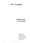
ver.: 1.14 - 25/7/2011 Service manual of HCE-IOV-102 and HCE-IOV-201 Overview Please read and understand this document before using the products, save this document for later use. Product specifications and accessories may be changed at any time, some specifications of the products may be changed without any notice. This is a generic manual, it’s possible that your system is different: follow the instructions in this manual and in other user guides and schematics shipped with your vision system. For further information contact the technical assistance. The information in this document has been carefully checked and is believed to be accurate. However, no responsibility is assumed for clerical, typographical, or proofreading errors, or omissions. Copyright Under the copyright laws, neither this publication nor the software may be copied, photocopied, reproduced, or reduced to any electronic medium or machine-readable form, in whole or in part, without the prior written consent of VEA s.r.l.. HQV® and VEA® are registered trademarks of VEA s.r.l. Vedo™ and Brain Vector™ are trademarks of VEA s.r.l. Warranty VEA’s exclusive warranty is that the products are free from defects in materials and workmanship for a period of one year from date of sale by VEA.VEA makes no warranty or representation, express or implied, regarding noninfrigement, merchantability, or fitness for particular purpose of the products. Any buyer or user acknowledges that the buyer or user alone has determined that the products will suitably meet the requirements of their intended use. VEA disclaims all other warranties, express or implied. Limitations of liability VEA shall not be responsible for special, indirect, or consequential damages, loss of profits or commercial loss in any way connected with the products, whether such claim is based on contract, warranty, negligence, or strict liability. In no event shall responsibility of VEA for any act exceed the individual price of the product on which liability is asserted.In no event shall VEA be responsible for warranty, repair, or other claims regarding the products unless VEA’s confirms that the products were properly handled, stored, installed, and maintained and not subject to contamination, abuse, misuse, or inappropriate modification or repair. VEA shall not be responsible for conformity with any standards, codes, or regulations that apply to the combination of products in the customer’s application or use of the product. At the customer’s request, VEA will provide applicable third party certification documents identifying ratings and limitations of use that apply to the products. This information by itself is not sufficient for a complete determination of the suitability of the products in combination with the end product, machine, system, or other application or use. Never use the products for an application involving serious risk to life or property without ensuring that the system as a whole has been designed to address the risks, and that the vea product is properly rated and installed for the intended use within the overall equipment or system. Dimensions and weights are nominal and are not to be used for manufacturing purposes, even when tolerances are shown. VEA shall not be responsible for the user’s programming or configuration of a programmable or configurable product, or any consequence thereof. Tables of contents 1. GENERAL FEATURES OF THE MODULES HCE-IOV-102 AND HCE-IOV-201 ......................................................... 3 2. SPECIFICATIONS OF THE HCE-IOV-102 MODULE ....................................................................................................... 3 3. SPECIFICATIONS IN STROBE MODE HCE-IOV-102-S(H). ........................................................................................... 4 4. SPECIFICATIONS OF THE HCE-IOV-201 MODULE ....................................................................................................... 4 5. POWER SUPPLY OF THE HCE-IOV-102-S(H) MODULE. ............................................................................................... 5 6. INSULATION OF THE HCE-IOV-102 MODULE ............................................................................................................... 5 7. SUMMARY TABLE OF THE JUMPERS. ............................................................................................................................. 5 8. DRIVERS INSTALL AND ELECTRONIC CONNECTIONS. ............................................................................................ 6 9. SERIAL PORT CONFIGURATION....................................................................................................................................... 9 10. USE OF HYPERTERMINAL ............................................................................................................................................ 10 11. I/O PROTOCOL .................................................................................................................................................................. 11 12. SUMMARY SPECIFICATIONS HCE-IOV-102. ............................................................................................................ 14 13. SUMMARY SPECIFICATION HCE-IOV-201. .............................................................................................................. 14 2 1. General features of the modules HCE-IOV-102 and HCE-IOV-201 The modules HCE-IOV-102 and HCE-IOV-201 permits an interface between PC and 8 inputs and 8 digital outputs via USB port. Is possible to mount the module HCE-IOV-102 on DIN rail. The outputs and inputs of the module HCE-IOV-102 are optoisolated; the outputs have a temporary overcurrent protection with LED signal up to 400% of output current for up to 2 sec. The modules are used (depending on version) for the control of a strobe light source, the commands allow to put some outputs in parallel in order to increase their power. 2. Specifications of the HCE-IOV-102 module Power: 24VDC 2A Input: 8 optoisolated digital inputs, a voltage between 10VDC and 30VDC (3-10 mA) is recognized as logical 1, while a voltage between 0 and 3VDC is considered as logical 0. The voltages must be considered respect the 0V which supplies the device. Input filters are programmable from 0.25 mSecs up to 255mSecs ATTENTION: in the communication protocol, inputs and outputs are numbered from 0, also in the label, while on the PCB of the device the numbers starts from 1. N. input Clamp HCE-IOV-102 0 1 2 3 4 5 IN1 IN2 IN3 IN4 IN5 IN6 Inputs 6 7 IN7 IN8 USB Power 24VDC LED POWER OVERLOAD Outputs N. output Clamp HCE-IOV-102 0 1 2 3 4 5 6 7 Q1 Q2 Q3 Q4 Q5 Q6 Q7 Q8 Output: 8 optoisolated digital outputs (PNP transistor) protected from temporary overcurrent, resistive and inductive load allowed (voltage 24V DC), max current for a single output: 500mA, max current for each output with all outputs turned on: 200mA. 3 3. Specifications in strobe mode HCE-IOV-102-S(H). The device permits to supply power to LED lamps in strobe mode, also with high current using multiple parallel outputs. With the MLH command can be configured the high-speed strobe connected directly to the rising edge of an input, the scanning timings of a non filtered input are 0.25mSecs, the minimum duration of a pulse is 200 μSecs. For maximum supportable current look at the table below ATTENTION: the HCE-IOV-102-S module is protected from temporary overcurrent, a continuous overcurrent (more than 2 sec) or a short circuit will irreparably damage the module. These damages are not covered by warranty. The use of the module in overcurrent mode, with variable duty cycles, is under the responsibility of the user. ATTENTION: the HCE-IOV-102-SH module is NOT protected from overcurrent and short circuits. These damages are not covered by warranty. Duty cycle (cycle duration <1 sec) HCE-IOV-102-S Max current on a single output (all other off, or with currents <50 mA) HCE-IOV-102-S Max global supportable current HCE-IOV-102-SH Max current on a single output (all other off, or with currents <50 mA) HCE-IOV-102-SH Max global supportable current > 50% 20% < 50% < 20% 3A 4A 6A 3A 4A 6A 6A 8A 10 A 6A 8A 10 A 4. Specifications of the HCE-IOV-201 module Power: from USB Input: 8 TTL digital inputs, input filters are programmable from 0.25 mSecs up to 255mSecs. Output: 8 TTL digital outputs (10mA). ATTENTION: the HCE-IOV-201 is not optoisolated and is sold as electronic component, damages caused by electrostatic discharges or wrong connections are not covered by warranty. The terminals of the module have in sharing the 0V of the ground with the 0V of the USB port. Without an inside insulation, these terminals expose the PC to potential risks, because there is a direct connection. In case of unexpected return of voltages there can be damages to the module and the PC. 4 5. Power supply of the HCE-IOV-102-S(H) module. HCE-IOV-102-S and HCE-IOV-102-SH modules may also work with USB unplugged. ATTENTION: When the product is used with the USB port connected, remove the jumpers OVER and JPOWER, otherwise malfunctions may occur to the PC, a temporary use is accepted by the pc for a few minutes.. ATTENTION: If JPOWER jumper is connected also the OVER jumper must be connected, otherwise malfunctions may occur to the PC and the module. These damages are not covered by warranty. 6. Insulation of the HCE-IOV-102 module Is possible to remove the optoisolation between the external 0V and the 0V of the PC by connecting the OVER jumper. This will reduce the problems of interference in case there are large and instable differences of potential between external 0V and the 0V of the PC. 7. Summary table of the jumpers. The OVER jumper connects the internal 0V (PC-USB) to the external 0V (24V DC). The JPOWER jumper supplies the power to the microprocessor module when USB port isn't connected to the PC. Below there is a table of the combination of jumpers. Description Factory Settings OVER The device is optoisolated and the CPU is powered by PC HCE-IOV-102-L NO The device isn’t optoisolated (USB 0V is connected to YES external 0V) and the CPU is powered by PC The device isn’t optoisolated (USB 0V is connected to HCE-IOV-102-S(H) YES external 0V) and the CPU is powered by external 24V (lowered to 5V) WRONG AND DANGEROUS COMBINATION NO 5 JPOWER NO NO YES YES 8. Drivers install and electronic connections. Download the updated drivers from site: www.vea.it. The driver can be found on products/optics and other/IO device menu (In english: http://www.vea.it/sito2010/prodotti/varie/IO/io_en.htm). Unzip the files in a temporary directory (e.g.: “c:\temp”). ATTENTION: follow the steps below in the right order: 1. connect the device to the power supply unit (24V), connecting the negative terminal first (0V) 2. connect the device to the PC with a USB cable (not included in the product). The connection between PC and the device needs an USB cable. This cable is like that used in printers, namely: Type A connector on the PC side and Type B connector on the IO side. In factory automation we recommend using the cable HAC-IOV-180 with double-ferrite, with high impedance, which reduces the signal losses caused by electromagnetic interference. ATTENTION: tips to reduce interference for industrial use. In factory automation, there may be devices that emit electromagnetic interference. For this reason, for a continuous operation of the product we give the following advice: Do not route the USB cable along with outgoing cables from the inverter, motor drives, robots, and other power devices do not put the HCE-IOV device near inverters, motor drives, power robots. Do not use USB cables for PC office. Do not use USB cables longer than 2 m in case of heavy and unstable potential differences between the PC and 0V external, can cause interference, you can put the OVER jumper (see Chapter 6). Type A connector of the USB cable. Connect to the Vision System Type B connector of the USB cable. Connect to the HCE-IOV-101 module 6 Wait for device detection. On Windows XP, the following screens will appear, respond as indicated in the yellow ovals. 7 Everything should be done two times, once for the driver and once for the physical emulation of the serial port. 8 9. Serial port configuration The module emulates a serial port of your PC, for know which "COM " is emulated go on the "My Computer " icon, right click on this icon, "properties", "Hardware", "Device Manager" button. ATTENTION: every new device is detected with a different COM number; this is done to allow the connection of multiple IO devices. To force the number of COM go on the "VEA I / O ", double click of the mouse, on the window select "Port Settings", "Advanced" button and select the COM number, then click OK. We recommend forcing the port number if you do not plan future expansions, in this way, if there will be a module replacement, the COM port number will remain the same. In case of a new install of the device or an additional module install, the computer will require new drivers, so it's good to keep them always available, we suggest using our driver and do not perform the automatic search of the driver of Windows, it is possible that compatible drivers, but with different features than the drivers provided, will be installed. The device operates at 115200 baud 8N1 without flow control. 9 10. Use of HyperTerminal To test the module I / O can use Windows HyperTerminal (in Windows XP is under Programs / Accessories / Communications, does not exist in Vista and Windows 7, can be downloaded from internet) configure it in this way: Menu "File> Properties" "Connect To"and select the modem port of the device. Press the "Configure" and set the fields as in the picture, then press OK Go to "Settings " and press the "ASCII Setup"as described in the picture below. Set the fields as in Figure on the left, then press OK 10 11. I/O Protocol Legend: <CR>: control character equivalent to code ASCII=13 [n]: variable code, usually “n” is a number “standard replies”: $ = ok ? = error (if [ASCII mode = on] must be followed by <CR>) Note: in ASCII MODE=ON every number is readable otherwise must be considered as ASCII code, tutti i numeri sono leggibili altrimenti sono da intendersi come codice ascii, for example the same command (in BASIC string): ASCII=on “w26”+chr$(13) ASCII=off “w” + chr$(26) Note: commands that start with M are always considered as ASCII = on, also in ASCII=off mode. Command ? MA[n] <CR> MDDI<CR> Description Device identification n=0 : ASCII mode OFF, n=1: ASCII mode ON (default ascii=1) Return the number of digital inputs MDDO<CR> Return the number of digital outputs. MER <CR> (from ver. 1.13 ) MEW <CR> (from ver. 1.13) The following commands are read from the EEPROM: MA, MF, MI, MKIW, MLH, MMIW The following commands are written to EEPROM: MA, MF, MI, MKIW, MLH, MMIW ATTENTION: Writing to EEPROM takes about 300 mSecs, in the meantime, the module will not process any command Inputs filter, [f] set me mSecs of the filter e.g.: MF100<CR> sets a filter on the inputs of 100 mSecs Max value: 255 mSecs Min value: 0 mSecs (equivalent to approximately 0.25 mSecs) Interrupt mask (also with (ascii=off)) MI[p(nnn)]/[d(nnn)]<CR>: set the interrupt mask for each port, e.g.: « MI0/255<cr> » ensures that all inputs on port 0 (first port) generate an interrupt MF[f] <CR> MI default: no interrupts for inputs 11 Return V1.13 VEA USB I/O<CR> standard [n]<CR> e.g.: 8 [CR]) [n]<CR> e.g.: 8 [CR]) standard standard standard standard return to the command every change of state of an input contained in the interrupt mask (ascii=off) ![d] 2 bytes (ascii=on) ![d(nnn)]<CR> for the meaning of [d] see command “w” Command MKN[n] <CR> Description Internal numerical key [n]= integer number to be converted returns an unambiguous number (the coding is the same for all modules) e.g.: “MKN541<CR>” (upon request, the numerical key can be customized) MKIW[n] <CR> Writes a configurable numerical key [n]= integer number to store e.g.: “MKIW1234<CR>” ATTENTION: the key will be saved in EEPROM MKIR[n] <CR> Configurable numerical key [n]=integer number to be converted returns an unambiguous number (the coding depends on the number stored with the function MKIW) e.g.: “MKIR541<CR>” MLH[i][p][u] High speed strobe (in microseconds) <CR> [i]= trigger input for the pulse [p]=byte of the port 0 (0= strobe disabled) [u]=impulse duration in microSecs (range from 200 to 200000) e.g.: “MLH 4 15 500<CR>” when the input 4 switches to high, the outputs 0,1,2,3, corresponding to the decimal number 15, turn on for 0.5 mSecs ATTENTION: This instruction has priority over any other function of the module; during the pulse the module can not perform any action, so other commands can not operate correctly during the pulse. MLR <CR> Turns off all flashing/strobe MLS[n][u][d] Flashing or strobe <CR> [n]=output number 0 – 71 [u]=time ON in mSecs (0= turns off the flashing or the pulse) [d]=time OFF in mSecs (0= unique pulse) e.g.: “MLS 2 1000 1000<CR>” flashing on output 2 MLGS[n1][n2][u] Flashing/strobe group [d] <CR> [n1]=first output number (0 – 71) [n2]=last output number (0 – 71) [u]= time ON in mSecs (0= turns off the flashing or the pulse) [d]= time OFF in mSec (0= unique pulse) e.g.: “MLGS 0 7 10 0<CR>” strobe pulse on outputs from 0 to 7, duration 10 mSecs Return [n]<CR> es: 49847891 [CR]) standard [n]<CR> es: 112822816 [CR] standard standard standard standard To use the codes of the keys is recommended to store a number of sequences "number to be transformed", "number transformed" and build a program that requires them randomly. Command MMIR <CR> Description Reads an integer number without sign Returns the number memorized with function MMIW Return [n]<CR> e.g.: 1234 [CR] MMIW[n]<CR> Writes an integer number without sign e.g.: “MMIW1234<CR>” standard 12 MMDRESET<CR> Restores the default values except the numerical keys. ATTENTION: the values stored in the EEPROM will not be (from ver. 1.13) modified MRIG[n1][n2] Reads the input associated to an interrupt for a group of port <CR> Returns the actual values in interrupt format [n1]=number of the first port (0 – 8) [n2]=number of the last port (0 – 8) e.g.: “MRIG 0 2<CR>” reads the input linked to interrupt on the ports 0,1,2 MTR<CR> MTT<CR> Comando W w R r standard for each input contained in the interrupt mask (ascii=off) ![d] 2 bytes (ascii=on) ![d(nnn)]<CR> for the meaning of [d] see the command “w” Time from power on, in mSecs [n]<CR> e.g.: 3451234 [CR] Returns the number of the pulse per second used in the high [n]<CR> speed mode e.g.: 1430615[CR] Descrizione Writes a byte on the outputs (ascii=off) W[p][d]: writes a byte (p=port, d=data) 3 bytes total. (ascii=on) W[p(nnn)]/[d(nnn)]<CR>: writes a byte ego. « W0/23<cr> » writes 23 on the port 0 (the first port) note: separator "/" can also be a space Writes an output (ascii=off) w[d=(0-127)]: set 0 on the corresponding output (up to 15 ports: 0-7 port 0, 8-15 port 1, etc) 2 bytes total (ASCII=off) w[d=(128-255)]: set 1 on the corresponding output (up to 15 ports: 128-135 port 0, 136-143 port 1, etc.) (ASCII=on) w[d=(0-127)]<CR>: set 0 on the corresponding output (up to 15 ports: 0-7 port 0, 8-15 port 1, etc.) (ASCII=on) w[d=(128-255)] <CR>: set 1 on the corresponding output (up to 15 ports: 128-135 port 0, 136-143 port 1, etc.) Reads the input one byte at a time (ascii=off) R[p]: reads one byte (p=port) 2 bytes total. (ascii=on) R[p(nnn)]<CR>: reads one byte (p=port) e.g. « R1<cr> » reads from port 1 (the second port) Reads an input (ASCII=off) r[d=(0-127)]: reads the corresponding input (up to 15 port: 0-7 port 0, 8-15 port 1, etc.) 2 bytes total (ASCII=on) r[d=(0-127)]<CR>: reads the corresponding input (up to 15 ports: 0-7 port 0, 8-15 port 1, etc.) Risposta standard standard (ascii=off) [d] the data in one byte (ascii=on) [d(nnn)]<CR> 0 (off) 1 (on) Please Note: The module is sold in various versions depending on the country and uses, it is possible that some commands are not available for the version you purchased. 13 12. Summary Specifications HCE-IOV-102. product type fixing number of inputs number of outputs optoisolation maximum current for a single output ON(the others OFF) ver. L maximum current for a single output ON (the others OFF) ver. S maximum current for a single output ON (the others OFF) ver. SH maximum current for a single output ON (all outputs ON) ver. L maximum current for a single output ON (all outputs ON) ver. S maximum current for a single output ON (all outputs ON) ver. SH supply voltage PC interface dimension weight operating temperature range storage temperature range relative humidity 13. industrial optoisolated usb i/o din rail 8 PNP (0V common) 8 PNP (0V common) 1000V 1,5 A 3A 6A 250 mA at 30º - 200 mA at 50º 375 mA at 30º - 250 mA at 50º 750 mA at 30º - 500 mA at 50º 12 – 30 V (typical 24V) USB 1.1 70 x 91 x h 63 mm 123 g 0º 55º -30º 70º max 90% at 25ºC (77°F) Summary specification HCE-IOV-201. product type fixing number of inputs number of outputs maximum current on a single output supply voltage PC interface dimension usb i/o microcircuit pin or 2 holes 8 TTL 8 TTL 10 mA USB (5V) USB 1.1 54,7(without USB connector) x 24,2 x h 7,5 (13,5 with pin connector) mm 9g 0º 55º -30º 70º max 90% a 25º weight operating temperature range storage temperature range relative humidity Features may change without notice. 14