1
Installation and user’s guide
H-5259-8500-05-A
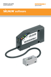
NCi-5 non-contact tool setting interface
1
English
Installation and user’s guide
NCi-5 non-contact tool setting interface
This page is intentionally left blank
1-i
© 2007 - 2013 Renishaw plc. All rights reserved.
Renishaw plc or its subsidiaries.
This document may not be copied or reproduced in whole
or in part, or transferred to any other media or language,
by any means, without the prior written permission of
Renishaw.
All other brand names and product names used in this
document are trade names, trade marks, or registered
trade marks of their respective owners.
The publication of material within this document does not
imply freedom from the patent rights of Renishaw plc.
Equipment requiring attention under warranty must be
returned to your equipment supplier.
Disclaimer
Unless otherwise specifically agreed in writing between
you and Renishaw, if you purchased the equipment from
a Renishaw company the warranty provisions contained
in Renishaw’s CONDITIONS OF SALE apply. You should
consult these conditions in order to find out the details of
your warranty but in summary the main exclusions from
the warranty are if the equipment has been:
RENISHAW HAS MADE CONSIDERABLE EFFORTS
TO ENSURE THE CONTENT OF THIS DOCUMENT
IS CORRECT AT THE DATE OF PUBLICATION BUT
MAKES NO WARRANTIES OR REPRESENTATIONS
REGARDING THE CONTENT. RENISHAW EXCLUDES
LIABILITY, HOWSOEVER ARISING, FOR ANY
INACCURACIES IN THIS DOCUMENT.
Warranty
•
neglected, mishandled or inappropriately used; or
Changes to equipment
•
modified or altered in any way except with the prior written agreement of Renishaw.
Renishaw reserves the right to change specifications
without notice.
If you purchased the equipment from any other supplier,
you should contact them to find out what repairs are
covered by their warranty.
Trade marks
RENISHAW and the probe symbol used in the
RENISHAW logo are registered trade marks of Renishaw
plc in the United Kingdom and other countries. apply
innovation and names and designations of other
Renishaw products and technologies are trade marks of
Renishaw part no: H-5259-8500-05-A
Issued: 05.2013
Patents
Features of the NCi-5 non-contact interface and related
products are subject to the following patents and patent
applications:
CN100394139CN101674918
CN1202403CN1660541
EP1050368EP1144944
EP1502699EP1506073
EP1562020EP2152469
1-ii
Preliminary information
JP4520240JP4521094
JP4695808KR0746932
WO2008/135744TW200909120
TW-NI-178572US2010/0051783
US6496273
US6635894 US6878953US7053392
US7312433B2
Other patents pending.
EC DECLARATION OF CONFORMITY
Renishaw plc declares that the NCi-5 non-contact interface
complies with the applicable standards and regulations.
Contact Renishaw plc at www.renishaw.com/nci-5 for the full EC
declaration of conformity.
WEEE directive
FCC
Information to user (FCC Section 15.19)
This device complies with Part 15 of the FCC rules. Operation is
subject to the following conditions:
1.
This device may not cause harmful interference.
2.
This device must accept any interference received, including
interference that may cause undesired operation.
Information to user (FCC Section 15.105)
This equipment has been tested and found to comply with the
limits for a Class A digital device, pursuant to part 15 of the FCC
Rules. These limits are designed to provide reasonable protection
against harmful interference when the equipment is operated in
a commercial environment. This equipment generates, uses and
can radiate radio frequency energy and, if not installed and used
in accordance with this installation guide, may cause harmful
interference to radio communications. Operation of this equipment
in a residential area is likely to cause harmful interference, in
which case you will be required to correct the interference at your
own expense.
Information to user (FCC Section 15.21)
The user is cautioned that any changes or modifications, not
expressly approved by Renishaw plc or authorised representative,
could void the user’s authority to operate the equipment.
The use of this symbol on products and/or accompanying
documentation indicates that the product should not be mixed with
general household waste upon disposal. It is the responsibility of
the end user to dispose of this product at a designated collection
point for waste electrical and electronic equipment (WEEE) to
enable reuse or recycling. Correct disposal of this product will help
to save valuable resources and prevent potential negative effects
on the environment. For more information, please contact your
local waste disposal service or distributor.
Information to user (FCC Section 15.27)
The user is cautioned that any peripheral device installed with this
equipment, such as a computer, must be connected with a highquality shielded cable to ensure compliance with FCC limits.
Warnings and cautions
!
Warnings
1-iii
CNC machine
Use of controls or adjustments or performance
of procedures other than those specified within
this publication may result in hazardous radiation
exposure.
CNC machine tools must always be operated
by competent persons in accordance with the
manufacturer’s instructions.
Switch off electrical power to the NCi-5 interface
before carrying out maintenance on non-contact
(NC) tool setting and tool breakage detection
products.
Information for the machine
supplier
Caution – Laser safety
The NCi-5 interfaces with Renishaw laser-based
non-contact tool setting and tool breakage
detection products. Laser safety guidelines and
safety rules are described in the appropriate NC
tool setting product guides.
If the equipment is used in a manner not
specified by the manufactirer, the protection
provided by the equipment may be impaired.
It is the machine supplier’s responsibility to
ensure that the user is made aware of any
hazards involved in operation, including those
mentioned in Renishaw product documentation,
and to ensure that adequate guards and safety
interlocks are provided.
Do not rely on probe signals to stop machine
movement.
1-iv
General information
NCi-5 maintenance
Operating conditions
No routine maintenance is required.
Protection provided
by enclosure
IP20
Altitude
Maximum 2000 m
Operating temperature
+5 °C to +55 °C (+41 °F to +131 °F)
Storage temperature
–25 °C to +70 °C (–13 °F to +158 °F)
Remove dust from the external surfaces with a
dry cloth.
Electrical ratings
Absolute maximum
supply voltage
11 Vdc to 30 Vdc
Maximum rated current
0.5 A
±50 mA pk
SSR contact ratings
±30 Vdc pk
Maximum Relative humidity
relative humidity 80% for temperatures up to +31 °C (+87.8 °F) decreasing linearly to 50% relative humidity at +40 °C °F).
(104
1-1
Contents
General
Introduction..........................................................................................................................1-2
Power supply.......................................................................................................................1-2
Input / output over-current protection..................................................................................1-2
Connectors CN1 and CN2.........................................................................................................1-5
Interface LEDs ..........................................................................................................................1-6
Switches
Switch locations...................................................................................................................1-8
Switch settings – SW1.........................................................................................................1-9
Switch settings – SW2.......................................................................................................1-11
Switch settings – SW3.......................................................................................................1-12
SSR2 output selections.....................................................................................................1-13
Operating modes
Tool setting mode..............................................................................................................1-14
High-speed tool breakage detection..................................................................................1-16
Latch mode........................................................................................................................1-16
Dimensions and mounting arrangements................................................................................1-17
Wiring
NC1 systems.....................................................................................................................1-18
NC3 system.......................................................................................................................1-19
NC4 system.......................................................................................................................1-20
Connecting to the CNC.....................................................................................................1-21
Controlling the laser of an NC1 separate system..............................................................1-22
Controlling the laser of an NC4 system.............................................................................1-23
Sharing the Skip with an auxiliary probe...........................................................................1-24
Controlling the air supply to an NC4 system.....................................................................1-25
Parts list...................................................................................................................................1-26
1-2
General
Introduction
power then identify and rectify the cause of the
fault.
CNC machine tools using Renishaw NC1, NC3
or NC4 non-contact (NC) systems for tool setting
or broken tool detection require an interface unit.
The NCi‑5 unit converts signals from the NC unit
into voltage‑free, solid state relay (SSR) outputs
for transmission to the CNC machine control.
The nominal current when connected to an NC
unit is as follows:
The NCi-5 interface unit should be installed in the
CNC control cabinet. Where possible, site the unit
away from potential sources of interference such
as transformers and motor controllers.
NOTE: To disconnect the power supply, remove
the wires from the terminals.
Only qualified persons should install and adjust
switches on the interface. Remove the mains
supply from the NCi-5 unit before removing the
cover.
Power supply
The NCi-5 interface can draw its power from the
CNC machine’s nominal 12 Vdc to 24 Vdc supply.
This must be an appropriate single fault tolerant
power supply which must comply to IEC 60950.
The supply to the NCi-5 is protected by a 0.5 A
resettable fuse. To reset the fuse, remove the
NC1
300 mA @ 12 Vdc, 130 mA @ 24 Vdc
NC3 120 mA @ 12 Vdc, 70 mA @ 24 Vdc
or NC4
Input / output over-current
protection
Each of the SSR (solid state relay) outputs is
protected by a 50 mA resettable fuse.
The auxiliary relay output is protected by a
200 mA resettable fuse.
The NC3 and NC4 are protected by a resettable
current protection circuit.
General
1-3
Interface label
Removable cover
Diagnostic LEDs
Connector CN1
(10-way)
Connector CN2
(15-way)
1-4
General
NCi-5 interface
label
Connectors CN1 and CN2
10-way connector (CN1)
Connector CN1 is used to connect the noncontact unit to the NCi-5 interface. The interface
automatically detects which NC unit has been
connected.
15-way connector (CN2)
Connector CN2 is used to connect the NCi-5
interface to the CNC machine tool.
Terminals 1 – 2
Used to monitor the signal from the NC3 or NC4.
Voltage range: 0 Vdc to 9 Vdc.
Terminals 3 – 6
This is an auxiliary output that can be used to
control external devices. Devices may include an
LED, a buzzer, an air blast.
This output can also be used with an NC1
separate system and NC4 systems to switch
the transmitter unit on/off independently of the
1-5
receiver. Alternatively, it can act as a skip-sharing
module to switch between a non-contact tool
setting device and an OMI/MI 12 for spindle
probing. This output is fused at 200 mA.
Terminals 7 – 8
This is an SSR output that can be configured to
be either normally-open (N/O) or normally-closed
(N/C). The output is fused at 50 mA.
Terminals 9 – 10
This is an SSR output that can be configured to
be either normally-open (N/O) or normally-closed
(N/C), as well as providing a pulsed, level or
oscillating output. The output is fused at 50 mA.
Terminals 11 – 12
This is used to select the operating mode.
Terminals 13 – 15
This is used to supply power to the interface.
1-6
Interface LEDs
Interface LED states
Five LEDs are fitted on the front of the NCi-5
interface. These provide the operator with a visual
indication of the system’s status.
Status LED (when used with NC3 or
NC4)
When the system is in the set-up mode, the LED
displays red.
Aux. relay status LED
Green
Not lit
Auxiliary relay energised
Auxiliary relay not energised
Tool set mode LED
Following a successful set up, the Status LED
indicates the status of the NC system to the
operator. The colours and associated states are
described in the table on page 1-7.
Green
Not lit
When the system is in the set-up mode, the LED
changes from red to amber to green as the beam
voltage increases.
This is the high-speed tool breakage mode.
If the LED is amber after exiting from the set-up
mode, this indicates that set-up has not been
successful and must be repeated.
Status LED (when used with NC1)
Green
Red
The probe is untriggered
The probe is triggered
Mode selected
Mode not selected
Tool break mode LED
Green
Not lit
Mode selected
Not selected
Latch mode LED
Green
Not lit
Mode selected
Not selected
Interface LEDs – Status LED (when used with NC3 or NC4)
LED colour
Tool setting mode
High speed broken tool
detection mode
1-7
Latch mode
Green-amber The system operating
Not applicable
(flashing at
voltage is too high.
1 Hz)
The system will continue to
function, but for optimum
performance repeat the
set-up and alignment
procedures.
The output is not latched.
The system operating
voltage is too high.
The system will continue to
function, but for optimum
performance repeat the
set-up and alignment
procedures.
Green
The beam is clear.
The probe is untriggered.
Not applicable
The beam is clear.
The output is not latched.
Amber
The beam is partially
blocked. X
The output is not latched.
The beam is blocked.
The output is not latched.
The beam is blocked by a
rotating tool. X
Red
The beam is blocked.
The probe is triggered.
The output is latched.
The tool is broken.
The output is latched.
No light
✸
No power to the unit
If the laser beam is clear and the LED is
amber, this indicates that the system will continue
to function, but for optimum performance
maintenance is required.
Refer to the publication “NC4 installation and
maintenance guide”, Renishaw part number
H‑2000‑5230, for details of the possible actions
required.
1-8
Switch locations
Removable cover
(used to access switches SW2
and SW3. These switches only
need to be accessed during
installation)
Cover tab – depress to
remove cover
Switch SW1
(used during
installation and normal
operation)
Switch SW2
Switch SW3
Switch settings – SW1
1-9
IMPORTANT: Setting a switch
When setting a switch to either the On or Off position,
apply firm pressure to make sure it is fully in position.
Switch bank SW1
1 Not used
On
Off
Not used.
2 NC set-up
On
Off
Used when setting up an NC4 system. Set this switch to On so
that the alignment voltage can be maximised. After maximising the
voltage, set the switch to Off so that the automatic gain circuitry
can fine-tune the operating voltage.
When setting up the NC1 or NC3, set this switch to On for
5 seconds then set it to Off. This automatically configures the NCi‑5
interface to operate with the NC1 or NC3.
3 Drip rejection On
When the drip rejection mode is set to On, the effects of individual
drops of coolant on measurements are filtered out.
Off
NOTE: For safe operation, set the spindle speed and spindle
override as described below.
1-10
Switch settings – SW1 (continued)
Switch bank SW1 (continued)
4 Spindle rpm
500 1000
Used with drip rejection. For safe operation, the spindle speed must
be fixed at a whole multiple, e.g. 1000, 2000, or 3000; or 500, 1000,
or 1500, and the spindle override must be disabled.
Switch settings – SW2
1-11
Switch bank SW2
!
CAUTIONS: With the SSR output switch(es) set to OFF, i.e. normally-open (N/O), the respective output will remain in a non-triggered state if the power supply is interrupted and/or a poor connection is made to the SSR.
If using SSR2 as an oscillating or pulsed output for a trigger signal to the control, the level output SSR1
must be used to guarantee a reliable probe status check.
Switch
OnOff
1
SSR1
N/C
N/O
Sets the SSR output to either normally-closed (N/C) or
normally‑open (N/O).
2
SSR2
N/C
N/O
As above.
3
SSR2
Level Pulsed
Type 1
Sets the SSR2 output to level or pulsed.
Refer to page 1-13.
4
Pulse
20 ms 100 ms
width
Sets the SSR2 pulsed output width to either 20 ms or 100 ms. It
also sets the minimum pulse width of the SSR1 output to either
20 ms or 100 ms.
If the pulse width is set to 20 ms, the cycle time for the latch mode
functions is reduced and the spindle speed is five times faster.
In certain cycles, ensure the maximum rpm of the tool is not
exceeded.
NOTE: For the cycle to work, the pulse width value selected must
be the same as the value that is configured in the tool setting
software.
1-12
Switch settings – SW3
Switch bank SW3
Switch
1
OnOff
M-code 1 Low High
Active Determines whether the input responds to an active - High or
active - Low signal.
2 M-code 2 Low
Active
High
As above.
3
Not used –
–
Not used.
4
SSR2
Osc. As Type 2
SW2-3
Sets the SSR2 output to oscillating or as per SW2-3.
Refer to the page 1-13.
NOTES:
If an M-code is not connected to terminal 11,
SW3-1 must be set to High.
If an M-code is not connected to terminal 12,
SW3-2 must be set to High.
SSR2 output selections
1-13
SSR2 Type 1 and SSR2 Type 2
CAUTION: If using SSR2 as an oscillating or pulsed output for a trigger signal to the control, !
the level output SSR1 must be used to guarantee a reliable probe status check.
The SSR2 output can be configured for three different types pulsed, level or oscillating.
The selection of SSR2 type is derived from the position of two switches, SW2-3 and SW3-4.
The table for this logic is as follows:
SW2-3
SSR2 Type 1
SW3-4
SSR2 Type 2
Output type
Off
Off
Pulsed
On
Off
Level
Off
On
Oscillating
On
On
Oscillating
NOTE: On certain machine controllers there is a
delay between the start of a measurement move
and the machine controller becoming responsive
to a change in trigger status. In this case use
the oscillating output to ensure the trigger is
detected when the machine controller becomes
responsive.
1-14
Operating modes
Tool setting mode
This mode of operation allows functions such as system alignment, tool calibration, length and diameter
tool setting, and thermal compensation tracking.
No M-codes are required.
Tool setting without drip rejection
Beam clear
Clears
Blocks
Laser
status
Beam clear Beam blocked Beam clear
Beam blocked
Blocks
Clears
< Pulse width
> Pulse width
Open
Level
Closed
Open
Pulse
Closed
Oscillating
Open
Pulse width
Pulse width
20 ms
Closed
20 ms
Pulse width = 20 ms or 100 ms, set by SW2-4
Diagrams shown for normally closed, invert for normally open
Pulse width
Operating modes
1-15
Tool setting with drip rejection
Beam clear
Clears
Blocks
Laser
status
Beam clear
Beam blocked
Drip filter
Beam blocked Beam clear
by drips
Blocks Clears
Drip filter
Open
Level
Closed
Open
Pulse
Closed
Oscillating
Open
Pulse width
Pulse width
20 ms
Closed
20 ms
Drip filter = 60 ms (1000 rpm) or 120 ms (500 rpm), set by SW1-4
Pulse width = 20 ms or 100 ms, set by SW2-4
Diagrams shown for normally closed, invert for normally open
S
S
< Drip filter
1-16
Operating modes
High-speed tool breakage
detection
This mode of operation allows rapid detection
of broken tools that are solid at the centre – for
example, drills and taps.
An M-code is required to activate the tool
breakage detection mode. The M-code must
supply a constant voltage of between 11 Vdc and
30 Vdc to CN2-11. To deactivate the tool breakage
function, the 11 Vdc to 30 Vdc supply must be
removed from CN2-11.
These selection levels can be inverted using
switch SW3-1, so that 0 Vdc is used to activate
tool breakage detection and 11 Vdc to 30 Vdc
is used to deactivate. If the M-code voltage is
floating when deactivated, a resistor is required to
pull up the voltage to the supply voltage (see the
figure below).
3 kΩ
0.5 W
3 kΩ
0.5 W
10
11
12
13
14
15
M-code 1 (tool breakage)
M-code 2 (latch mode)
Screen
0 Vdc supply
11 Vdc to 30 Vdc
Latch mode
This mode of operation allows functions such
as checking tools for missing inserts and profile
checking.
An M-code is required to activate the latch mode.
The M-code must supply a constant voltage
of between 11 Vdc and 30 Vdc to CN2-12. To
deactivate the latch mode function, the 11 Vdc to
30 Vdc supply must be removed from CN2-12.
These selection levels can be inverted using
switch SW3-2, so that 0 Vdc is used to activate
tool breakage detection and 11 Vdc to 30 Vdc
is used to deactivate. If the M-code voltage is
floating when deactivated, a resistor is required to
pull up the voltage to between 11 Vdc and 30 Vdc
(see the figure, left).
NOTE: If the status LED flashes red and green
this indicates that the NCi-5 is in a mode that is
not specified (both M-code 1 and M-code 2 have
been activated).
Information about the software for these cycles is
available from www.renishaw.com
Dimensions and mounting arrangements
M4 (x2)
34.6
(1.36)
134
(5.28)
98
(3.86)
Standard DIN rail mounting
Alternative mounting
1-17
1-18
Wiring – NC1 systems
Blue
White
Brown
Pink
NC1 fixed
Screen
NC1
separate
1
2
3
4
5
6
7
8
9
10
Laser OK (11 Vdc to 30 Vdc)
0 Vdc
11 Vdc to 30 Vdc
Ground
NCi-5 connector CN1
Blue
White
Brown
Pink
Rx
Screen
Tx
White
Brown ✸
Screen
1
2
3
4
5
6
7
8
9
10
Laser OK (11 Vdc to 30 Vdc)
0 Vdc
11 Vdc to 30 Vdc
Ground
✸ If the laser beam on
a separate system is
to be switched on and
off independently of the
receiver, do not connect
this brown wire to pin 3.
Connect the transmitter
as shown on page 1-22.
1-19
Wiring – NC3 system
NCi-5 connector CN1
NC3
White
Purple ✸
Blue
Black ✸
Red
Screen
Grey
1
2
3
4
5
6
7
8
9
10
Not used
Spare 0 Vdc
Spare 11 Vdc to 30 Vdc
Analogue output 1
Analogue output 2
0 Vdc
+12 Vdc
Ground
✸ Note that some early NC3 units do not have
a purple coloured wire but have one additional
black wire. Both black wires should be connected
to pin 7.
1-20
Wiring – NC4 system
NCi-5 connector CN1
White
NC4
Purple
Blue
Rx
Black
Red
Screen †
Grey
Tx
Black
Red ✸
Screen †
Grey
1
2
3
4
5
6
7
8
9
10
Not used
Spare 0 Vdc
Spare 11 Vdc to 30 Vdc
Analogue output 1
Set-up
Analogue output 2
0 Vdc
11 Vdc
Ground
Probe status
✸ If the laser beam is to be switched on and off
independently of the receiver, do not connect
this red wire to pin 8. Connect the transmitter as
shown on page 1-23.
† Do not connect screen
connections if the NC4
housing is connected
to the machine ground
reference (i.e. R ≤ 1Ω).
Wiring – connecting to the CNC
Digital
voltmeter
(used only
during
NC4 set-up)
CNC
machine
control
Machine
power
supply
1-21
NCi-5 connector CN2
1
Set-up DVM
2
Set-up DVM
3
Normally-open
4
Common
5
Normally-closed
6
Energise (11 Vdc to 30 Vdc)
7
SSR1 voltage-free
8
SSR1 voltage-free
9
SSR2 voltage-free
10
SSR2 voltage-free
11
M-code 1 (tool breakage)
12
M-code 2 (latch mode)
13
Screen
14
0 Vdc supply
15
11 Vdc to 30 Vdc supply
Auxiliary
relay
+ve
Power
supply
!
0 Vdc
CAUTION: If using SSR2 as an oscillating or pulsed output for a trigger signal to the control, the level output SSR1 must be used to guarantee a reliable probe status check.
1-22
Wiring – controlling the laser of an NC1 separate system
This arrangement allows the transmitter of an
NC1 separate system to be switched on and off
independently of the receiver.
NC1
separate
NCi-5 connector CN1
Blue
White
Brown
Pink
Rx
Screen
Tx
White
Screen
1
2
3
4
5
6
7
8
9
10
Laser OK (11 Vdc to 30 Vdc)
0 Vdc
11 Vdc to 30 Vdc
NCi-5 connector CN2
Ground
Brown
Stimulus, e.g. select M-code ✸
Power
supply
1
2
3
4
5
6
✸ High (11 Vdc to 30 Vdc) switches the laser on.
Low (0 Vdc), or floating, switches the laser off.
14
15
Normally-open
11 Vdc to 30 Vdc
Energise
(11 Vdc to 30 Vdc)
0 Vdc supply
Wiring – controlling the laser of an NC4 system
1-23
This arrangement allows the transmitter of
an NC4 system to be switched on and off
independently of the receiver.
NCi-5 connector CN1
White
NC4
Purple
Blue
Rx
Black
Red
Screen
Tx
Black
Screen
Grey
4
5
6
7
8
9
10
Analogue output 1
Set-up
Analogue output 2
0 Vdc
11 Vdc
Ground
Probe
status
Red
Grey
Stimulus, e.g. select M-code ✸
NCi-5 connector
CN2
1
2
3
4
5
6
Normally-open
Common
Energise
(11 Vdc to 30 Vdc)
✸ High (11 Vdc to 30 Vdc) switches the laser on.
Low (0 Vdc), or floating, switches the laser off.
Power
supply
14 0 Vdc supply
15 11Vdc to 30Vdc
supply
1-24
Wiring – sharing the Skip with an auxiliary probe
NCi-5 connector CN2
Aux. probe
output
Output (probe status)
Machine Skip input
CNC
machine
control
Machine
power
supply
Select M-code ✸
Skip supply voltage
1
2
3
4
5
6
7
8
9
10
11
12
13
14
15
Normally-open
Common
Normally-closed
Auxiliary
relay
Energise (11 Vdc to 30 Vdc)
SSR1 voltage-free
SSR1 voltage-free
Screen
0 Vdc supply
11 Vdc to 30 Vdc supply
✸ High (11 Vdc to 30 Vdc) selects the AUX probe (and may also send the start code).
Low (0 Vdc) or floating selects the NC probe.
Wiring – controlling the air supply to an NC4 system
1-25
NC4
Rx
Solenoid supply
voltage +Vdc
Tx
Imax = 200 mA
Air supply
Solenoid
Air supply
Vmax = 30 Vdc
NCi-5 connector CN2
1
2
3
4
5
6
Normally-open
Common
Normally-closed
Auxiliary
relay
Energise (11 Vdc to 30 Vdc)
Stimulus, e.g. select M-code ✸
Machine
power
supply
13
14
15
✸ High (11 Vdc to 30 Vdc) switches the air on.
Low (0 Vdc) or floating switches the air off.
Screen
0 Vdc supply
11 Vdc to 30 Vdc supply
1-26
Parts list
Type
Part number
Description
NCi-5 interface
A-5259-2000
NCi-5 interface and box with DIN rail mounting and two
terminal blocks.
NCi-5 terminal block
(10-way)
P-CN25-1053
10-way socket terminal for NCi-5 interface.
NCi-5 terminal block
(15-way)
P-CN25-0009
15-way socket terminal for NCi-5 interface.
Renishaw plc
New Mills, Wotton-under-Edge,
Gloucestershire, GL12 8JR
United Kingdom
T +44 (0)1453 524524
F +44 (0)1453 524901
E [email protected]
www.renishaw.com
For worldwide contact details, please
visit our main web site at
www.renishaw.com/contact
*H-5259-8500-05*