1
User Guide
Falcon 3-axis Non Contact Measurement System
INTRODUCTION
Falcon 3-axis
INTRODUCTION
Non Contact Measurement System
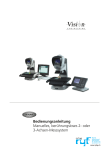
Vision Engineering's Falcon is a compact 3-axis non-contact semi-automated measurement system, designed to give
cost-effective accurate results.
The repeatable 5-position zoom optics provide the user with a high resolution clear image of intricate parts. Accurate
repeatable results are achieved in X and Y, by the NLEC calibrated stage, and in Z by the unique camera iris control
reducing the depth of field, therefore increasing the accuracy, repeatability and reproducibility of Z-axis measurement.
Health & Safety
Vision Engineering and its products conforms to the requirements of the EC Directives on Waste Electrical and
Electronic Equipment (WEEE) and Restriction of Hazardous Substances (RoHS).
EN61326-1:2006
FCC Part 15
EN60950-1:2001
WARNING: ALL EQUIPMENT PLUGGED INTO THIS UNIT MUST BE APPROVED TO EN60950-1:2001 AND
CHECK CURRENT RATING OF OUTPUT SOCKET IF USED.
UNPACKING
UN
PA
CK
IN
G
1
2
3
5
4
6
[
Ò
CONTENTS
PACKING CONTENTS
CONTENTS
Stand & objectives
1
Stage
1
Microprocessor
2
ASSEMBLY
Removing the transit protection
3
Attaching the LED array
3
Stage assembly (150 x 150mm)
4
Stage assembly (150 x 100mm)
4
Objective lens attachment
6
Microprocessor assembly
6
Cable connection
7
Stage alignment
7
Securing the stage (150 x 150mm)
8
Securing the stage (150 x 100mm)
8
Fitting the stage glass
9
Stage glass levelling
9
PRODUCT FAMILY
Falcon family tree
10
OPERATION & SETUP
Main system controls
11
HOW TO USE YOUR FALCON MEASURING SYSTEM
Start up
Best practice
Taking basic measurements
12
13
14
Getting the most from your Falcon
15
ROUTINE MAINTENANCE
Substage lamp changing
16
LED Ringlight replacement
16
OTHER SOLUTIONS FROM VISION ENGINEERING
Stereo inspection systems
17
Non-contact measuring systems
18
SERVICE & CALIBRATION RECORD
WARRANTY
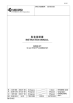
PACKING CONTENTS
PACKING &
Stand
CONTENTS
objectives
[
Ò
4
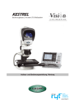
1 Stand
2 Low Magnification Objective lens
3 High Magnification Objective lens
4 LED ringlight
1
5 Toolkit
2
3
5
1
2
Stage
1 150mm x 100mm stage
3
2 150mm x 100mm adapter
3 150mm x 150mm Stage
www.visioneng.com/support
Falcon 3-axis Non Contact Measurement System
1
PACKING CONTENTS
1
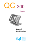
Microprocessor
1 Quadra-check 300 microprocessor
2 Microprocessor stand
3 Control box
3
2
2
Falcon 3-axis Non Contact Measurement System
www.visioneng.com/support
ASSEMBLY
Removing
ASSEMBLY
the transit protection
[
u
Ò
Remove the 3 securing screws u and then remove
the transit plate v.
u
w
Unscrew the rear transit bolt w in order to
remove it from the rear of the stand.
u
Note:
Keep the transit protection for
future transport of your Falcon.
It is highly recommended that
you refit the transit protection
whenever you transport your
system.
Attaching the LED array
u
u
Connect the flying lead socket u into the
fixed plug v on the LED array w.
u
v
Carefully position the array and secure it by
tightening the single securing screw x using
the Allen key supplied.
v
w
x
www.visioneng.com/support
Falcon 3-axis Non Contact Measurement System
3
ASSEMBLY
Stage assembly (150 x 150mm)
u
Use the stabilising foot u to ensure the base is stable.
u
Remove all red transit protection from the stage.
u
Check the stand base plate v and the underside of the 150 x
150mm stage w are clean and free of any debris.
u
Position the stage and secure it in position with
the bolts x and Allen key supplied but
DO NOT tighten them at this time.
Note:
Do not insert the fourth
mounting bolt until the system is
set up and the stage has been
aligned (see page 7).
x
x
x
w
v
u
Stage assembly (150 x 100mm)
u
Use the stabilising foot u to ensure the base is stable.
u
Check the stand base plate v and the underside of the
adapter w are clean and free of any debris.
u
Locate the adapter plate and secure it in position using the
bolts x provided.
x
x
x
x
w
v
u
4
Falcon 3-axis Non Contact Measurement System
www.visioneng.com/support
ASSEMBLY
u
Remove all red transit protection from the stage.
u
Check the adjustable pad y on the stage is retracted up
into the stage bottom plate. The adjustable pad is
controlled by the screw in the rear left hole in the
aperture under the stage glass.
u
Check the top of the adapter z and the underside of the stage are
clean and free of any debris.
u
Place the stage on the adapter and align the three
y
{
bolt holes {. Screw in the Allen bolts (using the
Allen key provided) but DO NOT tighten them at
this time.
{ {
z
www.visioneng.com/support
Falcon 3-axis Non Contact Measurement System
5
ASSEMBLY
Objective lens attachment
u
Place the objective lens u up into the head v and screw it into
position.
u
For further information, see Objective lens on page 12.
v
u
Microprocessor assembly
u
Locate the microprocessor body u on to its stand v, ensuring
the shoulder bolt w is used on the left-hand fixing (looking
u
from the front) and the spacer x and locking washer y are
correctly positioned on the right-hand fixing.
Note:
v
Do NOT overtighten either
fixing bolt.
w
y
x
6
Falcon 3-axis Non Contact Measurement System
www.visioneng.com/support
ASSEMBLY
Cable connection
I/O
Y/C
IN
X
Y
Z
LIGHTING/POWER
S-VIDEO
Z-AXIS
Input
110-240V
50-60 Hz
2.4 A MAX
FUSE
3.15 AT
Output
110-240V
50-60 Hz
1.0 A MAX
STAND I/O
QC300 I/O
MAINS POWER IN
WARNING: To comply with safety regulations, easy access to the mains socket must be maintained.
Stage alignment
u
Switch on Falcon.
u
Switch on the QC-300 and follow on screen instructions for crossing reference marks.
u
If a high magnification objective is being used, set the magnification control
u to 2. If a low magnification objective is being used, set the control to 4.
u
Focus on the three horizontal lines
in the centre of the alignment plate
attached to the stage.
u
Rotate the stage by hand until the
horizontal lines are parallel to the
horizontal crosshair on the QC-300.
u
Use the X axis control to check
reference lines remain parallel with
the crosshair.
u
Use the Allen key supplied to
tighten the stage bolts through the
v
w
w
w
v
v
appropriate holes in the alignment plate (v for the
150 x 150mm stage and w for the 150 x 100mm stage).
u
Remove the alignment plate.
Note:
u
If you need to remove the stage for any reason,
re-attach the alignment plate and ensure the horizontal
lines are parallel to the horizontal crosshair before removing
the stage.
www.visioneng.com/support
Falcon 3-axis Non Contact Measurement System
7
ASSEMBLY
Securing the stage (150 x 150mm)
u
Loosen the floating stage foot securing screw u.
u
Insert and screw in the last stage bolt v
and tighten fully.
u
Tighten the floating stage foot
securing screw.
v
u
Securing the stage (150 x 100mm)
u
8
u
Set the adjustable pad u using a flat headed
screwdriver. Adjust the screw until it just
touches down - DO NOT USE FORCE! If this
screw is over tightened, the base plate will
distort.
Falcon 3-axis Non Contact Measurement System
www.visioneng.com/support
ASSEMBLY
Fitting the stage glass
u
v
u
Fit the stage glass u into its recess, taking care to locate its
rear right-hand corner against the location springs v and on
to the supports w.
Note:
w
The above procedure should be used for both
types of stage.
w
w
w
Stage glass levelling
u
Use the X axis u and Y axis v controls to bring the rear right-hand corner of the stage
glass (fixed corner) w into view.
u
Use the stage focus control to bring the glass surface into sharp focus.
u
Use the axis controls to bring the front right-hand
corner into view. Use the relevant adjustable
glass support to bring the surface of the glass
into sharp focus.
u
Repeat for the remaining 2 corners.
u
Repeat the above steps if necessary until all 4 corners are in focus.
w
v
u
www.visioneng.com/support
Falcon 3-axis Non Contact Measurement System
9
PRODUCT FAMILY
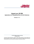
PRODUCT FAMILY
Falcon
family tree
Falcon Bench Stand
complete with Quadrant
ringlight
F-001
Objective
Lenses
High Mag F-004
Low Mag F-003
Standard
Core Instrument
LED Ringlight
F-010
Adapter for
100mm x 150mm
(6"x4") Stage
F-008
Low Mag
Optional Filter
FIL-1570
Green
filter
High Mag
LED Substage
Illuminator
F-009
Precision Measuring Stage
100mm x 150mm (6"x4")
F-005
Precision Measuring Stage
150mm x 150mm (6"x 6")
F-006
QC-300 2-axis
Microprocessor
H-049
Control Box
Including Cables
F-002
10
Dust Cover
F-011
Footswitch
K-016
Falcon 3-axis Non Contact Measurement System
www.visioneng.com/support
OPERATION & SETUP
OPERATION
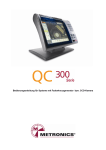
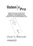
Main
system
& SETUP
controls
2
1
1 Zoom Control
2 Surface Illumination Iris Control
3 Substage Illumination Iris Control
4 Y Axis Control
5 X Axis Control
6 Fine Z Axis Rocker Control
7 On/off switch
8 Camera gain control
4
6
3
5
8
7
www.visioneng.com/support
Falcon 3-axis Non Contact Measurement System
11
HOW TO USE YOUR FALCON MEASURING SYSTEM
HOW TOup
Start
USE YOUR FALCON MEASURING SYSTEM
u
Switch on the Falcon, the ringlight power supply and the QC-300.
u
After the start up screen has displayed on the QC-300, follow the on-screen instructions and pass the reference
marks in all three axis.
u
Select the Light tab on the screen and adjust the illumination by selecting the icon and adjusting the intensity via
the slidebar.
u
Move the zoom to the desired position and focus on the subject by moving the head up or down using the
switch at the front of the stand.
To achieve optimum results from your Falcon measuring system, illumination and optics need to be optimised to
provide the best possible image. Certain lighting configurations are better for some applications than others.
Substage illumination should be used for profile measurement (optional colour filter available) whilst surface illumination is for
subjects with surface features.
Illumination and focus should be adjusted until the image is clear and bright, with good contrast. Maximum contrast
improves accuracy and repeatability.
Contact your nearest Vision Engineering branch or Distributor if you require further information.
Iris controls
The camera and substage are fitted with a 5 position (1-4 and Z) adjustable iris (1 = small, 5 or Z = large), allowing the
user to change the aperture of the lens. Changing the position of the controls results in the iris opening and closing.
This changes the amount of light passing back through the lens, slightly increasing or decreasing the depth of field,
ideal for subjects where greater surface definition is required. Position Z is used for height measurement. The Iris on
the substage is used to give sharper edge definition on profiles of 3 dimensional subjects.
Objective lens
Magnification table
Part No.
Description
Zoom Ratio
Total System
Magnification
Working Distance
Field of View
F-003
Low Magnification
Objective
1 - 5x
10x - 50x
91mm
2.7 - 13.5mm
F-004
High Magnification
Objective
1 - 5x
20x - 100x
61mm
1.35 - 6.75mm
Illumination options
Substage
12
•
•
Substage illumination used for the accurate measurement of through holes, profiles and edge features.
•
Can be used in conjunction with the surface illumination.
Adjust the intensity firstly by selecting the Substage icon from the Light toolbar, then by moving the marker up
or down the slidebar.
Falcon 3-axis Non Contact Measurement System
www.visioneng.com/support
HOW TO USE YOUR FALCON MEASURING SYSTEM
Ringlight (surface)
•
•
Surface illumination is used for surface features and blind holes etc.
•
For difficult to see edges, each quadrant can be switched on (yellow) and off (blank) as required, by selecting
the required quadrant ( just touch the screen on the segment required).
•
•
Switching quadrants off can create a shadow, used to increase the contrast of low contrast edges.
Adjust the intensity firstly by selecting the Ringlight icon from the Light toolbar, then by moving the marker up
or down the slidebar.
Can be used in conjunction with the surface illumination.
Best practice
To ensure the most accurate measurements are taken it is recommended that during the measurement process these
following guidelines are followed:
•
•
•
•
Do not adjust Magnification.
•
When viewing subject to locate measurement feature it is recommended that the
Falcon is focussed at max magnification then select lower mag if required.
Do not adjust camera or substage iris once image has been optimized.
Do not lean on or shake upper arm of your Falcon product.
When measuring subjects in the Z axis it is recommended that the approach direction
to achieve clear focus is the same for both references.
Ò
The Falcon Z axis is controlled by a highly sensitive variable speed switch. This has been
incorporated into the instrument in an intuitive ergonomic position, ideal for right or left
handed use (see opposite).
Light pressure on the switch will result in extremely fine adjustment of the Z axis,
enabling accurate repeatable focussing. As pressure on the switch is
increased the focussing adjustment speed will also increase.
Select the correct magnification for the component being measured,
based on size of component and field of view (see magnification table
on page 12). Ensure that the lens has been calibrated and selected on
the QC-300 (see QC-300 user guide for details).
Focus on the subject, using the control at the front of the stand to move the head, then
move the zoom control to the desired position.
To achieve the very best from your Falcon non-contact measuring system, you should carry out regular routine
maintenance as well as undertaking a schedule of service and calibration (see service and calibration record, at the
end of this user guide).
Camera gain control
Your Falcon System is fitted with camera auto gain control. This can be deactivated by using switch on front of
control box. This feature is useful when viewing low contrast parts with high levels of illumination or when taking
profile measurements with sub-stage illumination.
www.visioneng.com/support
Falcon 3-axis Non Contact Measurement System
13
HOW TO USE YOUR FALCON MEASURING SYSTEM
Taking basic measurements
Measurements can be made using any one of the four capture tools. Touch the screen to display the options.
•
Straight and Offset crosslines used for manually taking points (not used by
Falcon).
•
•
Single Edge tool for capturing single points on a feature.
Multi Edge tool for capturing multiple points on a feature, either inside or
outside the field of view.
Points are captured by aligning the tool over the edge of the feature being
measured and pressing enter to register the point. Points can be automatically
captured, by leaving the tool stationary over the feature for a preset time (seconds).
The multiedge tool is used to capture multiple points either inside or outside the
field of view. For inside the field of view position the tool in the centre of the
feature being measured, press enter to fire the points.
For features outside the field of view, take three points (circle) or 2 points (line) and
follow the green arrow to capture the remaining number of points (the number of
points can be increased/decreased if required).
Measuring features
The following geometric features can be measured:
•
Point - measured by capturing a single point.
•
Line - measured by capturing a minimum of two points.
•
Circle - measured by capturing a minimum of three points.
•
Slot - measured by capturing five points.
If you wish to measure the form of a feature, it is best to take at least 8 points to achieve a better result.
14
Falcon 3-axis Non Contact Measurement System
www.visioneng.com/support
HOW TO USE YOUR FALCON MEASURING SYSTEM
Measurement Microprocessor Settings and Advanced Features
Your falcon system has been configured and set up to work with the measurement microprocessor supplied.
Standard factory settings include calibrated magnifications for easy selection and measurement consistency using the
Zoom index system.
For information on how to set up and edit the standard features on the microprocessor please refer to the
microprocessor user manual.
The user manual also contains information relating to archiving images, writing measurement routines and other
advance measurement features that will enhance using the Falcon 3 axis measurement system.
Getting the most from your Falcon
Routine maintenance (see page 16)
•
•
•
The outside of the instrument should be wiped down to remove dirt and dust.
The instrument and accessories should be checked for loose or damaged components.
When not in use, protect your Falcon with the dust cover.
Consumable & replacement parts
Description
Specification
Part Number
Stage glass
150mm x 100mm
K-018
Stage glass
150mm x 150mm
201-B0686
Surface light LED array
20 LEDs, 1,100 lux (filtered)
F-001
Substage LED
330 lux (filtered)
MN-006
Environmental considerations
Falcon is an accurate, industrial gauging instrument. To achieve the optimum accuracy and repeatability, the following
considerations should be taken into account
•
•
•
•
•
Position the Falcon on a firm, rigid and level table.
Avoid locating the instrument near to a source of vibration.
Do not place the instrument close to a radiator or similar heat source.
Do not place the instrument close to a cold temperature source such as an air conditioning unit.
Do not position the instrument in direct sunlight, or where bright reflections will prevent a comfortable viewing
position.
www.visioneng.com/support
Falcon 3-axis Non Contact Measurement System
15
ROUTINE MAINTENANCE
ROUTINE MAINTENANCE
Substage
lamp changing
u
Disconnect the unit from the mains supply.
u
Carefully turn the stand on its side.
u
Remove the two bolts u from the Substage Illuminator
w
base plate v and remove it, complete with Substage
x
Illuminator unit w.
u
Disconnect the inline connector x and
remove the substage illuminator unit.
u
Fit the new unit by reversing the above
procedure.
u
v
u
LED Ringlight replacement
u
Using the Allen key supplied, unscrew the securing screw u
at the rear of the ringlight assembly.
u
Lower the assembly and disconnect the inline connector v.
u
To replace the LED ringlight, reverse the above procedure.
u
v
16
Falcon 3-axis Non Contact Measurement System
www.visioneng.com/support
OTHER SOLUTIONS FROM VISION ENGINEERING
Vision Engineering
OTHER
SOLUTIONS
manufactures
FROMa VISION
wide range
ENGINEERING
of stereo inspection and non-contact measuring systems. For all
product information, please visit our website.
Stereo inspection systems
Product
Picture
Lentis
Features
Description
• 2.5 dioptres.
• Multi layered anti reflective
coated lens.
• x4 - x20 Magnification.
• Shadow-free LED cold
Mantis
Alpha
illumination, both surface and
substage.
• Long working distances,
large depth of field.
• x2.1 – x160 magnification.
• Camera option.
• Expanded Pupil eyepieces.
A state of the art bench magnifier for
inspection, manipulation and material
rework.
The Mantis family is a unique range or
optical systems without eyepieces, for
intricate tasks requiring superb quality
viewing over long periods of use.
Available with universal arm or rigid
bench stand option.
Expanded Pupil eyepiece stereo zoom
microscope. Available in boom and
bench stand configuration with a wide
range of optional accessories (e.g.
lighting, cameras)
• x8 – x50* (6.3:1 zoom ratio)
SX 45
click-stop stereo zoom
magnification (x200 max.).
• Affordable stereo zoom
microscope with first-class
performance.
• Long-life (up to 6,000 hours),
true colour LED illumination.
• Wide range of options and
configurations.
• Extra long working distance
(115mm*).
• X2.1 – X120 magnification.
• 77mm – 1.75mm field of
Lynx
view.
• Camera option.
• Eyepieceless viewing system.
Designed as an affordable stereo zoom
microscope, the SX45 with its long
working distance, precision optics and
compact design is the perfect solution
to many industrial and biological
applications. With a wide array of
options and accessories, the SX45
allows further tailoring to individual
requirements.
Advanced eyepieceless stereo zoom
microscope. Available in boom and rigid
stand configuration with a wide range
of optional accessories (e.g. lighting,
cameras)
* with standard x1.0 objective
www.visioneng.com/support
Falcon 3-axis Non Contact Measurement System
17
OTHER SOLUTIONS FROM VISION ENGINEERING
Non-contact measuring systems
Product
18
Picture
Features
Description
Kestrel
• 150mm x 100mm stage.
• QC-200 Microprocessor.
• Eyepieceless viewing system.
• Video Edge Detection option.
Entry level, 2-axis measuring system.
Ideal for shop floor gauging
applications.
Hawk
manual
• 150mm x 150mm stage.
• 2 or 3 axis capability.
• Large stage option.
• Eyepieceless viewing system.
• Video Edge Detection option.
Advanced manual measuring system,
offering increased accuracy and
capacity. Operates with QC-200 and
QC-300 microprocessors.
Hawk
precision
• 200mm x 150mm stage.
• 2 or 3 axis capability.
• Eyepieceless viewing system.
• Video Edge Detection option.
High accuracy measuring system for 2
and 3 axis measurement. Operates
with QC-200 and QC-300
microprocessors or QC-5000 PC
software.
Hawk
automatic
• 200mm x 150mm stage.
• Video Edge Detection.
• Motorised stage movement.
• 2 or 3 axis capability.
Automated measuring system
combining optical viewing head with
PC based Video Edge Detection. 2 and
3 axis motorised stage movement
controlled by QC-5000 PC software.
Falcon 3-axis Non Contact Measurement System
www.visioneng.com/support
SERVICE & CALIBRATION RECORD
SERVICE
Falcon
Serial&
Number
CALIBRATION
________________
RECORD
Stage Serial Number ________________
Service Type
Comments
Date of Service
Date of Next Service
Company
Signature
WARRANTY
WARRANTY
This product is warranted to be free from defects in material and workmanship for a period of one year from the date of
invoice to the original purchaser.
If during the warranty period the product is found to be defective, it will be repaired or replaced at facilities of Vision
Engineering or elsewhere, all at the option of Vision Engineering. However, Vision Engineering reserves the right to refund
the purchase price if it is unable to provide replacement, and repair is not commercially practicable or cannot be timely
made. Parts not of Vision Engineering manufacture carry only the warranty of their manufacturer. Expendable
components such as fuses carry no warranty.
This warranty does not cover damage in transit, damage caused by misuse, neglect, or carelessness, or damage resulting
from either improper servicing or modification by other than Vision Engineering approved service personnel. Further, this
warranty does not cover any routine maintenance work on the product described in the user guide or any minor
maintenance work which is reasonably expected to be performed by the purchaser.
No responsibility is assumed for unsatisfactory operating performance due to environmental conditions such as humidity,
dust, corrosive chemicals, deposition of oil or other foreign matter, spillage, or other conditions beyond the control of
Vision Engineering.
Except as stated herein, Vision Engineering makes no other warranties, express or implied by law, whether for resale,
fitness for a particular purpose or otherwise. Further, Vision Engineering shall not under any circumstances be liable for
incidental, consequential or other damages.
For more information...
LIT 4412 R1.0/06/09
Vision Engineering has a network of offices and technical distributors around the world. For more information,
please contact your Vision Engineering branch, local authorised distributor, or visit our website.
Vision Engineering Ltd.
(Manufacturing)
Send Road, Send, Woking,
Surrey, GU23 7ER, England
Tel:
+44 (0) 1483 248300
Fax:
+44 (0) 1483 223297
Email: [email protected]
Vision Engineering Inc.
(Manufacturing & Commercial)
570 Danbury Road, New Milford,
CT 06776 USA
Tel:
+1 (860) 355 3776
Fax:
+1 (860) 355 0712
Email: [email protected]
Vision Engineering Ltd.
(Central Europe)
Anton-Pendele-Str. 3,
82275 Emmering, Germany
Tel:
+49 (0) 8141 40167-0
Fax:
+49 (0) 8141 40167-55
Email: [email protected]
Vision Engineering Ltd.
(France)
1 Rue de Terre Neuve, ZA Courtaboeuf,
91967 Les Ulis Cedex, France
Tel:
+33 (0) 164 46 90 82
Fax:
+33 (0) 164 46 31 54
Email: [email protected]
Vision Engineering Ltd.
(Commercial)
Monument House, Monument Way West,
Woking, Surrey, GU21 5EN, England
Tel:
+44 (0) 1483 248300
Fax:
+44 (0) 1483 248301
Email: [email protected]
Vision Engineering Inc.
(Commercial West Coast USA)
745 West Taft Avenue, Orange,
CA 92865 USA
Tel:
+1 (714) 974 6966
Fax:
+1 (714) 974 7266
Email: [email protected]
Nippon Vision Engineering
(Japan)
272-2 Saedo-cho, Tsuduki-ku,
Yokohama-shi, 224-0054, Japan
Tel:
+81 (0) 45 935 1117
Fax:
+81 (0) 45 935 1177
Email: [email protected]
Vision Engineering Ltd Italia
(Italy)
Via Cesare Cantù, 9
20092 Cinisello Balsamo MI, Italy
Tel:
+39 02 6129 3518
Fax:
+39 02 6129 3526
Email: [email protected]
Vision Engineering Ltd
(China)
11J, International Ocean Building,
720 Pudong Avenue, Shanghai,
200120, P.R. China
Tel:
+86 (0) 21 5036 7556
Fax:
+86 (0) 21 5036 7559
Email: [email protected]
Vision Engineering
(SE Asia)
Email: [email protected]
Distributor
Visit our multi-lingual website:
www.visioneng.com