1
CHAPTER 8 TROUBLESHOOTING
8
CHAPTER 8
TROUBLESHOOTING
This chapter describes how to find out and remedy the cause if the
E5AKT does not function properly.
Remedy E5AKT trouble in the order of the descriptions in this chapter
8.1 Initial Checks . . . . . . . . . . . . . . . . . . . . . . . . . .
82
8.2 How to Use the Error Display . . . . . . . . . . .
83
8.3 How to Use the Error Output . . . . . . . . . . .
85
8.4 Checking Operation Restrictions . . . . . . . .
86
8–1
8.1 Initial Checks
If trouble occurs, first of all check the following:
(1) Power supply
Make sure that the power supply is ON. Also, make sure that the pow
er supply is within the rated voltage range.
(2) Wiring
Make sure that all cables are properly connected.
(3) Communications conditions
When communicating via the RS232C, RS422 or RS485 interfaces,
make sure that the baud rate and other communications condition
settings on the host computer and E5AKT controller are matching,
and are within the permissible ranges.
If there appears to be nothing wrong after checking the E5AKT control
ler, and the same phenomenon continues, check the controller in more de
tail, for example, on the error display.
8–2
8.2 How to Use the Error Display
When an error has occurred, the No.1 display alternately indicates error
codes together with the current display item.
This section describes how to check error codes on the display, and the ac
tions you must take to remedy the problem.
Input error
Meaning
Input is in error.
Action
Check the wiring of inputs, disconnections, and shorts, and check the in
put type.
Operation at error
For control output functions, the manipulated variable matched to the set
ting of the MV at PV error" parameter (level 2 mode) is output.
Alarm output functions are activated as if the upper limit is exceeded.
Program operation is continued.
Memory error
Meaning
Internal memory operation is in error.
Action
First, turn the power OFF then back ON again. If the display remains the
same, the E5AKT controller must be repaired. If the display is restored
to normal, then a probable cause can be external noise affecting the con
trol system. Check for external noise.
Operation at error
Control output functions turn OFF (2 mA max. at 4 to 20 mA output, and
output equivalent to 0% in case of other outputs). Alarm output functions
turn OFF.
A/D converter error
Meaning
Internal circuits are in error.
Action
First, turn the power OFF then back ON again. If the display remains the
same, the E5AKT controller must be repaired. If the display is restored
to normal, then a probable cause can be external noise affecting the con
trol system. Check for external noise.
Operation at
error
Control output functions turn OFF (2 mA max. at 4 to 20 mA output, and
output equivalent to 0% in case of other outputs). Alarm output functions
turn OFF. Program operation is stopped.
8–3
CHAPTER 8 TROUBLESHOOTING
Calibration data error
This error is output only during temperature input, and is displayed for
two seconds when the power is turned ON.
Meaning
Calibration data is in error.
Action
E5AKT must be repaired.
Operation at
error
Both control output functions and alarm output functions operate. How
ever, note that readout accuracy is not assured.
Display range over
Meaning
Though not an error, this is displayed when the process value exceeds the
display range when the control range (setting range ^10%) is larger than
the display range (1999 to 9999).
• When less than 1999"
Operation
About Errors That
Occur During Motor Calibration
[
]
• When greater than 9999" [
]
Control continues, allowing normal operation.
If an error occurs during motor calibration, [
] is displayed on the No.2 display.
The following causes of errors are possible:
• Control motor or potentiometer malfunction
• Incorrect control motor or potentiometer wiring
• Potentiometer is not connected
8–4
8.3 How to Use the Error Output
8.3 How to Use the Error Output
The E5AKT controller allows you to assign error output to terminals as
outputs.
For details on output assignments, see 3.3 Setting Output Specifications
(page 37).
LBA
• LBA (Loop Break Alarm) can be used as a means for detecting loop
breaks when the control loop is not functioning normally. For details, see
page 426.
• LBA allows you to detect the following errors:
(1) Heater burnout (HBA)
(2) Output error (contact weld, damaged transistors, etc.)
(3) Sensor error (constant input values, etc.)
• If you use the LBA function, set the loop break detection time matched
to the control characteristics in the LBA detection time" parameter
(level 2 mode).
Input errors
• If you assign error 1 as the output, an error can be output to auxiliary
output 1 or auxiliary output 2 when input is in error. When this error
occurs, remedy by following the description for Input error".
A/D converter
error
• If you assign error 2 as the output, an error can be output to auxiliary
output 1 or auxiliary output 2 when the A/D converter is in error. When
this error occurs, remedy by following the description for A/D converter
error".
8–5
CHAPTER 8 TROUBLESHOOTING
8.4 Checking Operation Restrictions
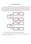
With the E5AKT controller, autotuning or selftuning sometimes do not
operate depending on how functions are combined. The table below sum
marizes the main operating restrictions.
If the E5AKT controller is not operating properly, first check whether op
erating conditions violate the restrictions in this table.
Inoperable or Invalid Functions
Restriction
AT Execution
Limitter Function
At heating and cooling
control
40%AT
At position-proportional
control
40% AT
Manipulated variable
Manipulated variable
MV change rate
At ON/OFF control
At AT execution
At reset
MV change rate
Other
ON/OFF control
Parameter setting
Manipulated variable
MV change rate
Items marked by a x" indicate combinations of conditions that are not acceptable during AT execu
tion.
8–6