Download Operating Instructions - Cont
Transcript
Drive Technology \ Drive Automation \ System Integration \ Services MOVITRAC® LTP Edition 12/2008 16766016 / EN Operating Instructions SEW-EURODRIVE – Driving the world 1 Important Notes................................................................................................. 4 1.1 Structure of the safety notes ..................................................................... 4 1.2 Application environment............................................................................ 5 1.3 Waste disposal.......................................................................................... 5 2 Safety Notes ...................................................................................................... 6 2.1 Installation and startup .............................................................................. 6 2.2 Operation and servicing ............................................................................ 7 3 General specifications ...................................................................................... 8 3.1 Input voltage ranges ................................................................................. 8 3.2 Product designation .................................................................................. 9 3.3 Overload capability ................................................................................... 9 3.4 Protection features .................................................................................. 10 4 Mechanical Installation ................................................................................... 11 4.1 Dimensions ............................................................................................. 12 4.2 IP20 / NEMA 1 housing: mounting and dimensions................................ 14 5 Electrical Installation ...................................................................................... 16 5.1 Prior to installation .................................................................................. 16 5.2 Installation ............................................................................................... 18 5.3 Optical interface ...................................................................................... 24 5.4 UL-compliant installation ......................................................................... 24 5.5 Electromagnetic compatibility.................................................................. 26 6 Startup.............................................................................................................. 27 6.1 Operating the keypad.............................................................................. 27 6.2 Easy startup ............................................................................................ 28 7 Operation and Service .................................................................................... 30 7.1 Drive status ............................................................................................. 30 7.2 Fault codes and history ........................................................................... 31 7.3 SEW electronics service ......................................................................... 33 8 Parameters....................................................................................................... 34 8.1 Parameter access and reset ................................................................... 34 8.2 Parameter specifications: ....................................................................... 36 8.3 Selection of Parameter P2-01, Digital Input Function ............................. 43 9 Software ........................................................................................................... 49 9.1 MODBUS Control.................................................................................... 49 10 Technical data ................................................................................................. 55 10.1 Conformance .......................................................................................... 55 10.2 Environmental ......................................................................................... 55 10.3 Output power and current ratings............................................................ 56 11 Index ................................................................................................................. 65 Operating Instructions– MOVITRAC® LTP 3 Important Notes Structure of the safety notes 1 1 Important Notes 1.1 Structure of the safety notes erschöpftOperating Instructions The safety notes in these operating instructions are structured as follows: Symbol SIGNAL WORD Nature and source of hazard. Possible consequence(s) if disregarded. • Symbol Measure(s) to avoid the hazard. Signal Word Example: Meaning Consequences if disregarded HAZARD Imminent hazard Severe or fatal injuries WARNING Possible hazardous situation Severe or fatal injuries CAUTION Possible hazardous situation Minor injuries STOP Possible damage to property Damage to the drive system or its environment NOTE Useful information or tip Simplifies drive system handling General hazard Specific hazard, e.g. electric shock Unless the information in the operating instructions is adhered to, it will be impossible to ensure: • Trouble-free operation • Fulfillment of any rights to claim under guarantee Consequently, read the operating instructions before you start working with the unit! The operating instructions contain important information about servicing. Therefore, keep the operating instructions close to the unit. 4 Operating Instructions – MOVITRAC® LTP Important Notes Application environment 1.2 1 Application environment The following applications are forbidden unless measures are expressly taken to make them possible: • Use in explosion-proof areas. • Use in environments with harmful substances: – – – – – – – 1.3 Oils Acids Gases Vapors Dust Radiated interference Other harmful environments • Use subject to mechanical vibration and shock loads in excess of the requirements in EN 50178. • If the inverter performs safety functions which have to guarantee the protection of machinery and people. Waste disposal Please follow the current instructions: dispose in accordance with the regulations in force: • Electronics scrap (printed-circuit boards) • Plastic (housing) • Sheet metal • Copper Operating Instructions – MOVITRAC® LTP 5 Safety Notes Installation and startup 2 2 Safety Notes MOVITRAC® LTP drive inverters may not perform safety functions without higher-level safety systems. Use higher-level safety systems to guarantee the protection of machinery and people. Do not use MOVITRAC® LTP drive inverters for any safety functions in conjunction with hoist applications. Use monitoring systems or mechanical protection devices as safety features to avoid possible injury or damage to property. 2.1 Installation and startup • Never install or operate damaged products. Please submit a complaint to the transport company immediately in the event of damage. • Installation, startup and service work on the unit only by trained personnel. The personnel must be trained in the relevant aspects of accident prevention andmust comply with the regulations in force (e.g. EN 60204, VBG 4, DIN-VDE 0100/0113/0160). • Follow the specific instructions during installation and startup of the motor and the brake! • Make sure that preventive measures and protection devices correspond to the applicable regulations (e.g. EN 60204 or EN 50178). Grounding the unit is a necessary protective measure. Overcurrent protection devices are a necessary protective measure. 6 • The unit meets all requirements for reliable isolation of power and electronics connections in accordance with UL508. All connected circuits must also satisfy the requirements for reliable isolation so as to guarantee reliable isolation. • Take suitable measures to ensure that the connected motor does not start up automatically when the inverter is switched on. To do this, you can connect binary inputs DI01 through DI03 to GND. • Integral solid state short circuit protection does not provide branch circuit protection. Branch circuit protection must be provided in accordance with the National Electrical Code and any additional local codes. Operating Instructions – MOVITRAC® LTP Safety Notes Operation and servicing 2.2 2 Operation and servicing WARNING Danger of electrical shock. High voltages are present in the terminals and in within the drive for up to 10 minutes after the electrical supply has been disconnected. Severe or fatal injuries. • Disconnect and isolate the MOVITRAC® LTP from the electrical supply at least 10 minutes before commencing any work on it. • Dangerous voltages are present in the output terminals and the cables and motor terminals connected to them when the unit is switched on. Dangerous voltages may also be present when the unit is inhibited and the motor at a standstill. • The unit is not necessarily deenergized when the LEDs and the 7-segment display are off. • Safety functions inside the unit or a mechanical blockage may cause the motor to stop. The removal of the source of the malfunction or a reset can result in an automatic restart of the drive. If, for safety reasons, this is not permissible for the driven machine, disconnect the unit from the supply system before correcting the fault. Operating Instructions – MOVITRAC® LTP 7 kVA 3 i f n General specifications Input voltage ranges P Hz 3 General specifications 3.1 Input voltage ranges Depending upon model and power rating, the drives are designed for direct connection to the following supplies: MOVITRAC® LTP 240 V units: 200 ... 240 V ± 10 %, 1-phase* / 3-phase, 50 … 60 Hz ± 5 % NOTE *It is also possible to connect 1-phase MOVITRAC® LTP units to 2-phases of a 200 ... 240 V, 3-phase mains. MOVITRAC® LTP 400 V units: 380 ... 480 V ± 10 %, 3-phase, 50 … 60 Hz ± 5 % MOVITRAC® LTP 525 V units: 480 ... 525 V ± 10 %, 3-phase, 50 … 60 Hz ± 5 % (Sizes 5 & 6 only) MOVITRAC® LTP 575 V units: 500 ... 600 V ± 10 %, 3-phase, 50 … 60 Hz ± 5 % Products used with a 3-phase supply are designed for a maximum supply imbalance of 3 % between phases. For input supplies which have a supply imbalance greater than 3 % (typically the Indian subcontinent and parts of Asia Pacific including China) we recommend that input chokes are used. 8 Operating Instructions – MOVITRAC® LTP General specifications Product designation 3.2 kVA i f n 3 P Hz Product designation MC LTP A 0015 2 0 1 1 00 (60 Hz) 60 Hz American version only 00 = Standard IP20 / NEMA 1 housing 10 = IP55 / NEMA 12 housing Type 3.3 20 = IP55 / NEMA 12 housing with switch 50 = 525 V, standard IP20 / NEMA 1 housing 0M = Optional Modbus Firmware Quadrants 1 = 1Q (without brake chopper) 4 = 4Q (with brake chopper) Connection type 1 = 1-phase 3 = 3-phase Interference suppression on the supply side 0 = class 0 A = class A B = class B Mains voltage 1 = 115 V 2 = 200 ... 240 V 5 = 380 ... 480 V 6 = 500 ... 600 V Recommended motor power 0015 = 1.5 kW Version A Product type MC LTP Overload capability All MOVITRAC® LTP units have a possible overload of: • 150 % for 60 seconds • 175 % for 2 seconds Operating Instructions – MOVITRAC® LTP 9 kVA 3 i 3.4 f n General specifications Protection features P Hz Protection features • Output short-circuit, phase-to-phase, phase-to-ground • Output over-current – Trip set at 175 % of rated drive current. • Overload protection – Drive delivers 150 % of rated motor current for 60 seconds. • Braking transistor protected against short-circuit. • Braking resistor overload (when enabled) • Over-voltage trip – Set at 123 % of drive maximum rated supply voltage. • Under-voltage trip • Over temperature trip • Under temperature trip – Drive will trip if enabled below –10 °C • Supply phase imbalance – A running drive will trip if there is a supply imbalance of >3 % persisting for more than 30 seconds. • Supply phase loss – A running drive will trip if one phase of a 3-phase supply is lost for more than 15 seconds. 10 Operating Instructions – MOVITRAC® LTP Mechanical Installation Protection features 4 4 Mechanical Installation • Carefully inspect the MOVITRAC® LTP prior to installation to ensure it is undamaged. • Store the MOVITRAC® LTP in its box until required. Storage should be clean and dry and within the ambient temperature range –40 °C to +60 °C. • Install the MOVITRAC® LTP on a flat, vertical, flame-resistant, vibration-free surface, within suitable housing. This should be according to EN 60529 if specific Ingress Protection ratings are required. • Do not place flammable material close to the drive. • The entry of conductive or flammable foreign bodies should be prevented. • The maximum operational ambient temperature is 50 °C and the minimum is 0 °C. • Relative humidity must be less than 95 % (non-condensing). • MOVITRAC® LTP units can be installed side by side with their heatsink flanges touching. This gives adequate ventilation space between them. If the MOVITRAC® LTP is to be installed above another drive or any other heat-producing device, the minimum vertical spacing is 150 mm. The enclosure should either be force-ventilated or large enough to allow natural cooling (see chapter "IP20 / NEMA 1 housing: mounting and dimensions" on page 14). Operating Instructions – MOVITRAC® LTP 11 Mechanical Installation Dimensions 4 4.1 Dimensions MOVITRAC® LTP is available in 2 housing versions: • Standard IP20 / NEMA 1 housing for use in switch cabinets • IP55 / NEMA 12 K version for size 1 and size 2 drives The IP55 / NEMA 12 K housing is protected against moisture and dust. Therefore, the drives can be operated indoors under harsh conditions. Electronically, the drives are identical and the only differences are the dimensions of the housing and the weight. 4.1.1 Dimensions of the IP20 / NEMA 1 housing b b a c A d c C B 54769AXX Width (B) Depth (C) Weight a Size 2 Size 3 Size 4 Size 5 Size 61) [mm] 155 260 260 520 1045 1100 [in] 6.10 10.20 10.20 20.47 41.14 43.31 80 100 171 340 340 340 [in] 3.15 3.94 6.73 13.39 13.39 13.39 [mm] 130 175 175 220 220 330 [in] 5.12 6.89 6.89 8.66 8.66 12.99 [mm] [kg] 1.1 2.6 5.3 28 68 Unit = 55 Choke = 27 [lb] 2.43 5.73 11.68 61.73 149.91 149.91 [mm] [in] b [mm] [in] c [mm] [in] d Power terminal torque settings Fixings 54770AXX Size 1 Dimension Height (A) 54781AXX 72 92 163 320 320 320 2.84 3.62 6.42 12.6 12.6 12.6 4 4 4 9.5 9.5 9.5 0.16 0.16 0.16 0.37 0.37 0.37 25 25 25 50 50 50 0.98 0.98 0.98 1.97 1.97 1.97 [mm] 105 210 210 420 945 945 [in] 4.13 8.27 8.27 16.54 37.21 37.21 [Nm] 1 1 1 4 8 8 [lb.in] 8.85 8.85 8.85 35.4 70.8 70.8 2 × M4 2 × M4 4 × M4 4 × M8 4 × M8 4 × M8 1) Size 6 comes with an external line choke 12 Operating Instructions – MOVITRAC® LTP Mechanical Installation Dimensions 4.1.2 4 Dimensions of the IP55 / NEMA 12 housing (LTP xxx –10 and –20) b a b c Z A X Y X d c C B 60198AXX 60200AXX Dimension 60199AXX Size 1 Size 2 200 310 [in] 7.9 12.2 [mm] 140 165 Height (A) [mm] Width (B) [in] 5.5 6.5 Depth (C) [mm] 165 176 [in] 6.5 6.9 Weight [kg] 2.3 4.5 [lb] 5.1 9.9 a [mm] 128 153 [in] 5 6 b [mm] 6 6 [in] 0.23 0.23 c [mm] 25 25 [in] 0.98 0.98 d [mm] 142 252 [in] 5.6 9.9 X [mm] 22 25 [in] 0.87 0.98 Y1) [mm] 22 22 [in] 0.87 0.87 Z1) [mm] 17 17 [in] 0.67 0.67 Power terminal torque settings [Nm] 1 1 [lb.in] 8.85 8.85 [Nm] 0.5 0.5 Control terminal torque settings Fixings [lb.in] 4.43 4.43 2 × M4 4 × M4 60497AXX 1) Glands Y and Z are flip out glands. Operating Instructions – MOVITRAC® LTP 13 Mechanical Installation IP20 / NEMA 1 housing: mounting and dimensions 4 4.2 IP20 / NEMA 1 housing: mounting and dimensions For applications that require a higher IP rating than the IP20 offered by the standard drive, the drive must be mounted in housing. The following guidelines should be observed for these applications: 4.2.1 • Housing should be made from a thermally conductive material, unless forced ventilation is used. • When vented housing is used, there should be venting above and below the drive to ensure good air circulation. Air should be drawn in below the drive and expelled above the drive. • If the external environment contains contamination particles (e.g. dust), a suitable particle filter should be fitted to the vents and forced ventilation implemented. The filter must be serviced and cleaned appropriately. • High moisture, salt or chemical content environments should use a suitably sealed (non-vented) housing. Dimensions of non-vented metal housing Sealed housing Drive power rating A B C D [mm] [in] [mm] [in] [mm] [in] [mm] [in] 0.75 kW 230 V 300 11.81 250 9.84 200 7.87 50 1.97 Size 1 1.5 kW 230 V 400 15.75 300 11.81 250 9.84 75 2.95 Size 2 1.5 kW 230 V 0.75 kW, 1.5 kW, 2.2 kW 400 V 2.2 kW 400 V 400 15.75 300 11.81 300 11.81 60 2.36 2.2 kW 230 V 4.0 kW 400 V 5.5 kW 575 V 600 23.62 450 17.72 300 11.81 100 3.94 Size 1 Size 2 B C D A D Figure 1: Housing 14 54784AXX Operating Instructions – MOVITRAC® LTP Mechanical Installation IP20 / NEMA 1 housing: mounting and dimensions 4.2.2 4 Dimensions of vented housing Vented housing Drive power rating Size 1 4.2.3 1.5 kW A B C D [mm] [in] [mm] [in] [mm] [in] [mm] [in] 400 15.75 300 11.81 150 5.91 75 2.95 Size 2 5.5 kW 600 23.62 400 15.75 250 9.84 100 3.94 Size 3 15 kW 800 31.50 600 23.62 300 11.81 150 5.91 Size 4 22 kW 1000 39.37 600 23.62 300 11.81 200 7.87 Size 4 37 kW – – – – – – – – Size 5 90 kW – – – – – – – – Size 6 160 kW – – – – – – – – Dimensions of force vented housing Force vented housing (with fan) Drive power rating A B C D [mm] [in] [mm] [in] [mm] [in] [mm] [in] Air Flow Size 1 1.5 kW 275 10.83 150 5.91 150 5.91 50 1.97 > 15 m3 / h Size 2 5.5 kW 320 12.60 200 7.87 250 9.84 75 2.95 > 45 m3 / h Size 3 15 kW 400 15.75 250 9.84 250 9.84 100 3.94 > 80 m3 / h Size 4 22 kW 800 31.50 500 19.69 300 11.81 130 5.12 > 300 m3 / h Size 4 37 kW 800 31.50 500 19.69 300 11.81 130 5.12 > 300 m3 / h Size 5 90 kW 1500 59.06 600 23.62 400 15.75 200 7.87 > 900 m3 / h Size 6 160 kW 1600 62.99 600 23.62 400 15.75 250 9.84 > 1000 m3 / h Operating Instructions – MOVITRAC® LTP 15 Electrical Installation Prior to installation 5 5 Electrical Installation It is essential to comply with the safety instructions in chapter 2 during installation. WARNING Danger of electrical shock. High voltages are present in the terminals and in within the drive for up to 10 minutes after the electrical supply has been disconnected. Severe or fatal injuries. • Disconnect and isolate the MOVITRAC® LTP from the electrical supply at least 10 minutes before commencing any work on it. • MOVITRAC® LTP units should only be installed by qualified electricians and in accordance with local and national regulations and codes of practice. • The MOVITRAC® LTP has an Ingress Protection rating of IP20. For higher IP ratings, use a suitable enclosure or the IP55 version. • Where the electrical supply to the drive is through a plug and socket connector, do not disconnect until 10 minutes have elapsed after turning off the supply. • Ensure correct earthing connections. See diagram in chapter "Drive and motor connection" on page 20. • The earth cable must be sufficient to carry the maximum supply fault current which normally will be limited by the fuses or motor circuit breaker. HAZARD Risk of fatal injury if the hoist falls. Severe or fatal injuries. • 5.1 16 MOVITRAC® LTP is not designed for use as a safety device in hoist applications. Use monitoring systems or mechanical protection devices to ensure safety. Prior to installation • Ensure that the supply voltage, frequency and number of phases (single or 3-phase) correspond to the rating of the MOVITRAC® LTP as delivered. • An isolator or similar should be installed between the power supply and the drive. • Never connect the mains power supply to the MOVITRAC® LTP output terminals U, V or W. • When installing 575 V inverters ensure the motor is always in STAR connection. • The cables are only protected when slow blow HRC fuses or a motor circuit breaker (MCB) are used. • Do not install any type of automatic switchgear between the drive and the motor. Wherever control cabling is close to power cabling, maintain a minimum separation of 100 mm and arrange crossings at 90 °. • Ensure that screening or armoring of power cables is effected in accordance with the connections diagram in chapter "Drive and motor connection" on page 20. • Ensure that all terminals are tightened to the appropriate torque. Operating Instructions – MOVITRAC® LTP Electrical Installation Prior to installation 5.1.1 5 Opening the front cover IP55 size 1 & 2 Insert a screwdriver into the opening as illustrated below to release the front cover. Z X Y X 64506AXX 5.1.2 Helpcard In the IP20 housing the helpcard is located in a separate slot above the display. In the IP55 housing the helpcard is attached to the inside of the front cover. Operating Instructions – MOVITRAC® LTP 17 Electrical Installation Installation 5 5.2 Installation Connect the drive according to the following diagram. Ensure that the motor terminal box connections are correct. There are two standards in general: Star and Delta. It is essential to ensure that the motor is connected in accordance with the voltage at which it will be operated. For more information, refer to the diagram below. Please refer to chapter 10 for the recommended cabling and wiring sizing. It is recommended that the power cabling should be 4-core PVC-insulated screened cable, laid in accordance with local industrial regulations and codes of practice. The ground terminal of each MOVITRAC® LTP should be individually connected directly to the site earth (ground) busbar (through the filter if installed) as shown. MOVITRAC® LTP ground connections should not loop from one drive to another. They should also not loop to or from any other equipment. Ground loop impedance must conform to local industrial safety regulations. To meet UL regulations, UL approved ring crimp terminals should be used for all earth wiring connections. 5.2.1 Motor terminal box connections Motors are connected in either Star, Delta, Double Star or Star Nema motors. The motor rating plate indicates the voltage rating for the method of connection, which must match the operating voltage of the MOVITRAC® LTP unit. R13 W2 U2 V2 W2 U2 U1 V1 U1 U V1 V W1 W Low voltage Δ 18 V2 W1 U V W High voltage 댴 Operating Instructions – MOVITRAC® LTP Electrical Installation Installation 5 R76 T6 T4 T5 T9 T7 T8 W3 U3 V3 T3 T1 T2 T3 L1 L1 L2 L1 T6 T4 T5 T9 T7 T8 T1 T2 L1 L2 W2 U3 U1 U2 V3 V1 V2 W2 U2 V2 W3 W1 Low voltage 댴댴 U1 V1 W1 High voltage 댴 DT / DV T4 T5 T6 U2 V2 W2 T7 T8 T9 U3 V3 W3 T1 T2 T3 U1 U V W Low voltage 댴댴 Operating Instructions – MOVITRAC® LTP T5 T6 U2 V2 W2 T7 T8 T9 V3 U3 T1 W1 V1 T4 T2 T3 W1 V1 U1 U W3 V W High voltage 댴 19 Electrical Installation Installation 5 5.2.2 Drive and motor connection WARNING Danger of electrical shock. Risk of exposure to high voltage may occur if the unit is wired incorrectly. Severe or fatal injuries. • It is essential to observe the connection sequence illustrated below. L1 L2/N PE -ph. F11/F12/F13 K10 (AC-3) L1 L2 V AC V AC F14/F15 [1] L3 Option ND.. input choke V AC L1' L2' L3' F14/F15 F14/F15 L1 L2 L3 [2] K11 (AC-3) K11 (AC-3) +V K11 (AC-3) Power section 10 [V+] +V U 11 BW.. / BW..-T braking resistor connection* 11 11 GND K12 (AC-3) K12 (AC-3) [3] GND * BR + W 10 10 [4] V 1 BG 2 3 BGE 4 5 DT/DV/D: Cut-off in the DC and AC circuits GND white 1 red BMK 2 3 blue 4 13 14 15 red white blue 1 BG 2 3 BGE 4 5 white red blue M 3-phase BW DT/DV/D: Cut-off in the AC circuit 64606AEN Figure 2: Wiring diagram for power section 20 [1] Mains supply contactor to drive [2] Mains supply to brake rectifier, switched simultaneously by K10 [3] Control contactor / relay, energized via the internal relay contact [4] in the drive and supplies the brake rectifier [4] Potential free relay contact inside the drive [V+] External power supply for energizing the control contactor / relay * Size 2 and above Operating Instructions – MOVITRAC® LTP Electrical Installation Installation 5 NOTE • Connect the brake rectifier using a separate supply system lead. • Supply via the motor voltage is not permitted! The 230 V and 400 V drives do not require a line choke on the supply unless the specified supply voltages cannot be guaranteed. Drives from 0.37 kW (0.5 HP) to 5.5 kW (7.5 HP) must be fitted with external line chokes if the quality of the supply cannot be guaranteed. An external line choke is always required for 575 V drives from 0.75 kW (1 HP) to 5.5 kW (7.5 HP). All drives with 7.5 kW (10 HP) or greater have a built-in choke and therefore do not need external chokes fitted to ensure transient protection. An external choke is required if 230 V or 400 V drives up to 5.5 kW (7.5 HP) are installed under the following conditions: • Local generator • Large loads on the same supply • High dV / dt voltage fluctuations e.g. when welders are being used • Outdoor pumping stations with exposed supply lines, which may be hit by lightening strikes. Always switch off the brake on the DC and AC sides with: • All hoist applications • Drives that require a rapid brake response time It is essential to adhere to the connection sequence of the brake connector. Incorrect connection will lead to irreparable damage to the brake. The connection to the brake rectifier requires a separate supply system cable. Supply from the motor voltage is not permitted. If the brake rectifier is installed in the switch cabinet the connecting cable between the brake rectifier and the brake must be routed separately to other power cables. Routing together with other cables is only permitted if the other cables are shielded. Set P2-13 to 3 to use the relay output to control the brake rectifier (BGx). 5.2.3 Motor thermal protection (TF / TH) Motors with an internal PTC over-temperature sensor (TF, TH or similar) can be connected directly to the MOVITRAC® LTP. A trip will then be displayed on the drive. The sensor is connected to terminal 1 (+24 V) and Digital Input 3. Parameter P2-01 must be set to external trip input to receive over-temperature trips. The trip level should be set to 2.5 k Ω. Operating Instructions – MOVITRAC® LTP 21 Electrical Installation Installation 5 5.2.4 Signal terminal overview The User Control terminals are available via an 11-way pluggable connector. All terminals are galvanically isolated, allowing direct connection to other equipment. STOP! Danger of damage to the MOVITRAC® LTP unit. Do not connect mains supply voltages to any terminals other than the user relay output. Doing so will result in permanent damage to the unit. The user relay output can handle up to AC 250 V. All other inputs only withstand DC 30 V without damage. The functionality of the inputs and outputs is user configurable. All operating modes are set up via the parameter set. Up to 100 mA can be sourced from the User +24 V output and up to 20 mA from the analog output. Relay common 0V Relay contact AO/DO 9 10 11 0V 0V 8 AI/DI AO/DO 7 +10 V 0V 6 DI 3 AI/DI 5 DI 2 +10 V 4 1 2 3 4 5 6 7 8 9 10 11 REV DI 3 3 DI 1 DI 2 2 +24 V DI 1 1 FWD +24 V Relay common IP55 with switch option Relay contact IP20 and IP55 64485AEN 64608AEN The signal terminal block has the following signal connections: Terminal no. 22 Signal Connection Description 1 +24 V +24 V ref out Ref. to activate DI1 ... DI3 (100 mA max.) 2 DI1 Digital input 1 3 DI2 / DO2 Digital input 2 / Digital output 2 Positive logic "Logic 1" input voltage range: DC 8... 30 V "Logic 0" input voltage range: DC 0... 8 V 4 DI3 / AI2 Digital input 3 / Analog input 2 Positive logic (P2-33) "Logic 1" input voltage range: DC 8... 30 V "Logic 0" input voltage range: DC 0... 8 V 0 ... 10 V, 0 ... 20 mA, 4 ... 20 mA 5 +10 V +10 V ref out 24 V ref for analog input (pot supply +, 100 mA max., 1 k Ω min.) 6 AI / DI Analog input (12 bit) Digital input 4 0 ... 10 V, –10 ... 10 V, 0 ... 24 V, –24 ... 24 V "Logic 1" input voltage range: DC 8 ... 30 V (P2-30) 7 0V 0 V common 0 V ref for analog input (pot supply –) 8 AO / DO Analog output (8 bit) Digital output 0 ... 10 V, 4 ... 20 mA analog 24 V, 20 mA digital (P2-36) 9 0V 0 V common 0 V ref for analog output 10 Relay contact Relay contact N.O. relay contact (AC 250 V / DC 30 V @ 5 A) 11 Relay common Relay common Operating Instructions – MOVITRAC® LTP Electrical Installation Installation Key information on the control terminal 5.2.5 • Maximum input voltage on any terminal: DC 30 V • All outputs are short circuit proof • Recommended potentiometer resistance: 1 k Ω • Digital input response time < 8 ms • Bipolar analog input response time < 16 ms. Resolution ±12-bit (0.025 %) • Second analog input response time < 16ms. Resolution +11-bit (0.05 %) • Analog / digital output response time < 16ms. Resolution 8-bit (0.25 %) 5 RJ11 Communication socket The RJ11 communication socket can be used to set up a RS-485 communication to the PC via UWS11A. With MOVITRAC® LTP units it is possible to use this RJ11 connector to set up a MODBUS communication network. [1] [2] [3] [4] [5] [6] 57406AXX [1] RS-485– / MODBUS 1) [2] RS-485+ / internal bus 1) [3] RS-485– / internal bus 1) [4] +24 V [5] 0V [6] RS-485+ / MODBUS 1) 1) The bit format is fixed as: 1 start bit, 8 data bits, 1 stop bit, no parity The internal bus works with 115 k Baud (bps). It can be used for drive-to-drive communication. In this case, up to 63 drives can communicate. The MODBUS RTU works between 9,6 and 115 k Baud (bps). It can be used to communicate directly with an external PLC or with a fieldbus gateway. In this case, up to 63 drives can be controlled via bus communication. Operating Instructions – MOVITRAC® LTP 23 
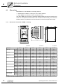
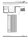
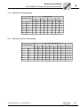
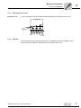
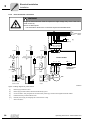
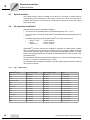
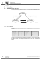
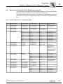
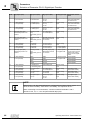
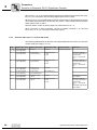
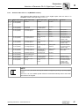
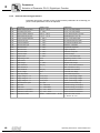
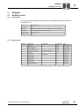
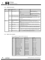
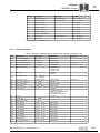
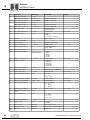
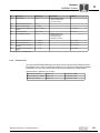
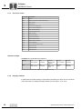
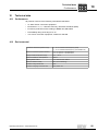
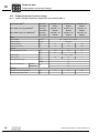
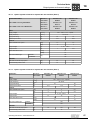
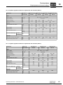
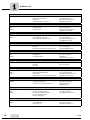
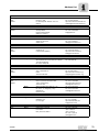
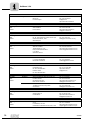
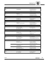
Electrical Installation Optical interface 5 5.3 Optical interface The optical interface, which is located next to the RJ11 connector, is mainly used for commissioning and monitoring the drive with a pocket PC. When LTP shell CE is installed, the pocket PC can be used to commission the drive and monitor the current status of the drive. 5.4 UL-compliant installation Note the following for UL-compliant installation: • The drives can be operated within an ambient temperature of 0 ... 50 °C. • Only use copper connection cables which can withstand ambient temperatures of up to 75 °C. • Permitted tightening torques for MOVITRAC® LTP power terminals are: – Sizes 1, 2 & 3 – Size 4 – Sizes 5 & 6 = 1 Nm / 8.9 lb.in = 4 Nm / 35.4 lb.in = 8 Nm / 70 lb.in MOVITRAC® LTP drive inverters are suitable for operation in voltage power systems with an earthed star point (TN and TT systems), which can supply a maximum supply current and a maximum supply voltage in accordance with the following table. The fuses listed in the following tables are the maximum permitted fuses for each inverter. Only use melting fuses. Only use tested units with a limited output voltage (Vmax = DC 30 V) and limited output current (I = < 8 A) as an external DC 24 V source. UL certification does not apply to operation in voltage supply systems with a non-earthed star point (IT systems). 5.4.1 24 200 ... 240 V Units MOVITRAC® LTP... Short circuit rating Max. supply voltage Fuses 0004 AC 5000 A AC 240 V AC 6 A / 250 V 0008 AC 5000 A AC 240 V AC 10A / 250 V 0015 AC 5000 A AC 240 V AC 20A / 250 V 0030, 0040, 022 AC 5000 A AC 240 V AC 32 A / 250 V 0055 AC 5000 A AC 240 V AC 50 A / 250 V 0075 AC 5000 A AC 240 V AC 80 A / 250 V 0110, 0150 AC 5000 A AC 240 V AC 100 A / 250 V 0185 AC 5000 A AC 240 V AC 125 A / 250 V 0220 AC 10000 A AC 240 V AC 160 A / 250 V 0300 AC 10000 A AC 240 V AC 200 A / 250 V 0370, 0450 AC 10000 A AC 240 V AC 300 A / 250 V 0550 AC 10000 A AC 240 V AC 350 A / 250 V 0750 AC 10000 A AC 240 V AC 400 A / 250 V 0900 AC 10000 A AC 240 V AC 500 A / 250 V Operating Instructions – MOVITRAC® LTP Electrical Installation UL-compliant installation 5.4.2 380 ... 480 V Units MOVITRAC® LTP... Short circuit rating Max. supply voltage Fuses 0008, 0015, 0022 AC 5000 A AC 480 V AC 10 A / 600 V 0040 AC 5000 A AC 480 V AC 20 A / 600 V 0055, 0075 AC 5000 A AC 480 V AC 32 A / 600 V 0110, 0150 AC 5000 A AC 480 V AC 50 A / 600 V 0185 AC 5000 A AC 480 V AC 80 A / 600 V 0220, 0300 AC 5000 A AC 480 V AC 100 A / 600 V 0370 AC 5000 A AC 480 V AC 125 A / 600 V 0450 AC 10000 A AC 480 V AC 160 A / 600 V 0550 AC 10000 A AC 480 V AC 200 A / 600 V 0750, 0900 AC 10000 A AC 480 V AC 300 A / 600 V 1100 AC 10000 A AC 480 V AC 350 A / 600 V 1320 AC 10000 A AC 480 V AC 400 A / 600 V 1600 AC 10000 A AC 480 V AC 500 A / 600 V Short circuit rating Max. supply voltage Fuses 0008 AC 5000 A AC 575 V AC 6 A / 600 V 0015, 0022, 0037 AC 5000 A AC 575 V AC 10 A / 600 V 0055 AC 5000 A AC 575 V AC 20 A / 600 V 0075, 0110 AC 5000 A AC 575 V AC 32 A / 600 V 0150 AC 500 A AC 575 V AC 25 A / 600 V 0220 AC 500 A AC 575 V AC 50 A / 600 V 5.4.3 5 575 V Units MOVITRAC® LTP... 0300 AC 500 A AC 575 V AC 63 A / 600 V 0450 AC 1000 A AC 575 V AC 80 A / 600 V Operating Instructions – MOVITRAC® LTP 25 Electrical Installation Electromagnetic compatibility 5 5.5 Electromagnetic compatibility The MOVITRAC® LTP range of frequency inverters is designed for use in machines and drive systems. They comply with the EMC product standard EN 61800-3 for variable speed drives. For EMC compliant installation of the drive system, follow the guidelines set out in council directive 2004/108/EC (EMC). 5.5.1 EMC immunity The MOVITRAC® LTP range meets the immunity levels defined in EN 61800-3 for both industrial and domestic (light industrial) environments. 5.5.2 EMC emissions The MOVITRAC® LTP EMC emission levels comply with the limit classifications defined in EN 61800-3 and EN 55014, allowing it to be used in both industrial and domestic (light industrial) applications. To obtain the best EMC performance the drives should be installed in accordance with the wiring guidelines in chapter "Installation" on page 18, thereby ensuring good earth connections for the drive system. Screened motor cable must be used to achieve compliance with the radiated emissions levels. The following table defines the conditions for the use of MOVITRAC® LTP in drive applications: 26 Drive type / rating Cat C1 (class B) 230 V, 1-phase ratings LTPA xxxx 2B1-x-xx No additional filtering required Use screened motor cable Cat C2 (class A) Cat C3 230 V, 3-phase ratings LTPA xxxx 2A3-x-xx Use <5 m screened motor cable No additional filtering required Use screened motor cable 400 V, 3-phase ratings LTPA xxxx 5A3-x-xx Use <5 m screened motor cable No additional filtering required Use screened motor cable 525 V & 575 V, 3-phase ratings LTPA xxxx 603-x-xx Use external filter Use screened motor cable Operating Instructions – MOVITRAC® LTP Startup Operating the keypad I 6 0 6 Startup 6.1 Operating the keypad Each MOVITRAC® LTP has an integrated keypad as standard, allowing drive operation and set up without any additional equipment. The keypad consists of 5 keys with the following functions: Start / Run Enable running of motor Stop / Reset Stop motor / Reset trip Navigate Press and release to display A / Hz / rpm Press and hold to enter / exit parameter edit mode Up Increase Parameter / Value Down Decrease Parameter / Value The Start / Stop buttons on the keypad are disabled when the parameters have their factory default settings. To enable the operation of the <start> / <stop> buttons on the keypad, set P1-12 to 1 or 2 (see chapter 8.2.1, "Standard parameters"). The Navigate key alone is used to gain access to the parameter edit menu. Pressing and holding this key (> 1 second) allows the user to toggle between the parameter edit menu and the real time display (where the drive operating status / running speed is displayed). By pressing this key (< 1 second) the user is able to toggle between the operating speed and operating current during drive operation. [1] [4] [2] [5] [3] [6] 54787AXX [1] Display [2] Start [3] Stop / Reset [4] Navigate [5] Up [6] Down NOTE To reset to factory default settings, press the Up, Down, and Stop buttons simultaneously for > 2 s. The display then shows "P-deF". Press the Stop button to acknowledge the change and to reset the drive. Operating Instructions – MOVITRAC® LTP 27 I 6 Startup Easy startup 0 6.2 Easy startup CAUTION Danger due to possible rotating shaft during auto-tune procedure. Minor injuries. • Uncouple the load from the motor. • Take precautionary measures to ensure that no risk is posed by possible rotation of the shaft. 1. Connect the motor to the drive, checking the connection for the motor voltage rating. 2. Enter motor data from motor nameplate: • • • P1-07 P1-08 P1-09 = motor rated voltage = motor rated current = motor rated frequency 3. Enable the drive by making a connection between terminal 1 and 2). The drive automatically carries out a static auto-tune where the motor winding is measured. Autotune is carried out only once after first comissioning. If auto-tune does not occur, set P4-02 to "1" to enable auto-tune. For safety reasons parameter P4-02 can only be set and enabled on the drive. 4. For high performance sensorless vector control set P1-14 to 101, P4-01 to 0 and P4-05 = cos Φ / power factor of motor (from motor nameplate). Setting P4-02 to 1 then starts auto-tune where the motor winding is measured. 6.2.1 Terminal mode (default setting) To operate in terminal mode (default setting): • Ensure that P1-12 is set to 0 (default setting). • Connect a switch between terminals 1 and 2 on the user terminal block. • Connect a potentiometer (1 k ... 10 k) between terminals 5, 6 and 7 with the wiper connected to pin 6. • Close the switch to enable the drive. • Adjust speed with the potentiometer. NOTE The default settings (P1-12 = 0 and P2-01 = 0) for the optional switch in the IP55 switch cabinet is FWD / REV. The motor speed can be set via potentiometer. 28 Operating Instructions – MOVITRAC® LTP Startup Easy startup I 6 0 6.2.2 Keypad mode To operate in keypad mode: • Change P1-12 to 1 (uni-directional) or 2 (bi-directional). • Place a wire link or switch between terminals 1 and 2 on the user terminal block to enable the drive. • Now press the <start> key. The drive enables at 0.0 Hz. • Press the <up> key to increase speed. • To stop the drive, press the <stop> key. • If the <start> key is now pressed, the drive will return to its original speed, unless configured to start from zero speed (see P2-19). (If bi-directional mode is enabled (P1-12 = 2), pressing the <start> key reverses the direction). NOTE The desired target speed can be preset by pressing the <stop> key whilst the drive is stopped. When the <start> key is subsequently pressed, the drive will then ramp to this speed. 6.2.3 Key parameters • Adjust the maximum and minimum speed limit using P1-01 and P1-02. • Adjust the acceleration and deceleration times using P1-03 and P1-04. • Set up the motor nameplate data in parameters P1-07 to P1-10. Operating Instructions – MOVITRAC® LTP 29 I 7 Operation and Service Drive status 0 7 Operation and Service To enable the operational status of the drive to be determined at any time, the following information is displayed: Status Mnemonic display Drive OK Static drive status Drive running Operational drive status Fault / trip Fault 7.1 Drive status 7.1.1 Static drive status The following list indicates which mnemonics will be displayed as drive status information when the motor is at a standstill. 7.1.2 Mnemonic Description StoP Drive power stage disabled. This message will be displayed when the drive is stopped and no faults are present. The drive is ready for normal operation. P-deF Default parameters loaded. This message will be displayed when the user invokes the command to load the factory default parameters. The reset button has to be pressed before the drive can be operated again. Stndby Drive is in standby. This message will be displayed 30 seconds after the drive is on 0 speed and the setpoint is 0 as well. Operational drive status The following list indicates which mnemonics will be displayed as drive status information when the motor is in operation. Use the <Navigate> button on the keypad to toggle between output frequency, output current and speed. 30 Mnemonic Description H xxx The drive output frequency is displayed in Hz. This message will be displayed when the drive is running. A xxx The drive output current is displayed in Amp. This message will be displayed when the drive is running. xxxx The drive output speed is displayed in rpm. This message will be displayed when the drive is running and the motor rated speed is entered in parameter P-09. . . . . . . (flashing dots) Output current of the drive exceeds the current which is set in P1-08. MOVITRAC® LTP will monitor the level and duration of the overload. Depending on the overload level, the MOVITRAC® LTP will trip with "I.t-trP". Auto-t Automatic motor parameter measurement is carried out to configure the motor parameters. Auto-tune runs automatically on first enable after parameter default operation and when P1-08 has been changed. No hardware enable is required to run auto-tune. C xxx Speed scaling factor. Referring to P2-21 and P2-22. Operating Instructions – MOVITRAC® LTP Operation and Service Fault codes and history I 7 0 7.2 Fault codes and history 7.2.1 Troubleshooting Fault finding chart Symptom Cause and Solution Overload or over-current trip on unloaded motor during acceleration Check Star / Delta terminal connection in motor. Rated operating voltage of drive and motor should match. The Delta connection always gives the lower voltage rating of a dual voltage motor. Overload or over-current – motor does not spin Check for locked rotor. Check that the mechanical brake is released (if fitted). Drive will not enable – display remains on "StoP" Check that the hardware enable signal is applied to digital input 1. Ensure that the User +24 V output voltage (between terminals 5 and 7) is correct. If not, check wiring to user terminal strip. Check P1-12 for terminal / keypad mode. If keypad mode selected, press the <start> button. Check that supply voltage is within specification. Drive runs incorrectly when in vector mode Ensure that the motor name plate data has been entered into P1-07, P1-08, P1-09 before the parameter auto-tune function has been carried out. Set P4-02 = 1 to carry out auto-tune. In very cold ambient conditions, drive will not power up If the ambient temperature is less than –10 °C, the drive may not power up. Ensure that a local heating source keeps the ambient above 0 °C in these conditions. Speed limit or rated frequency parameters cannot be set above 250 Hz, 500 Hz or 1000 Hz The maximum output motor frequency is limited by the switching frequency. Ensure that P2-24 is at least 16 times greater than the required motor output frequency before setting the required maximum or rated output frequency parameters. Extended menus cannot be accessed Ensure that P1-14 is set to the extended access code. This is “101” unless the code in P2-37 has been changed by the user. 7.2.2 Fault history The parameter P1-13 in the parameter mode holds a record of the most recent 4 trips and / or events that have occurred. Each trip will be displayed in abbreviated text, with the most recent trip being displayed first (on entering into the value of P1-13). Whenever a new trip occurs, this is entered at the top of the list and the other trips move down. The oldest trip will then be removed from the trip log. NOTE If the most recent trip in the trip log is an "under-voltage" trip, further under-voltage trips will not be entered into the trip log. This is to ensure that the trip log does not fill up with under-voltage trips which occur naturally every time the MOVITRAC® LTP is turned off. Operating Instructions – MOVITRAC® LTP 31 I 7 Operation and Service Fault codes and history 0 7.2.3 Fault codes Trip message Explanation Solution "P-dEF" Factory default parameters have been loaded. Press STOP key. Drive is ready to configure for required application. “O-I” Over-current on drive output to motor. Excess load on motor. Over temperature on drive heatsink. • • • • • • “I_t-trP” Drive overload trip, occurring when the drive has been delivering > 100 % rated current (set in P1-08) for a period of time. The display flashes to indicate an overload condition. • • • • • • Check motor and motor connection cable for ph-ph or ph-Earth short circuit Check load mechanically for a jam or stalled condition or shock loads. Ensure motor nameplate parameters are entered correctly, P1-07, P1-08, P1-09. If operating in Vector mode (P4-01 = 0 or 1): • also check motor power factor in P4-05. • reduce speed loop gain in P4-03. Ensure an autotune has been successfully completed for the connected motor. Increase the ramp-up time in P1-03. Increase acceleration ramp or decrease motor load. Check cable length is within drive specification. Ensure motor nameplate parameters are entered correctly, P1-07, P1-08, P1-09. If operating in Vector mode (P4-01 = 0 or 1), also check motor power factor in P4-05. Ensure an autotune has been successfully completed for the connected motor. Check the load mechanically to ensure it is free and no jams, blockages or other mechanical faults exist. "OI-b" Brake channel over current. Over current in the brake resistor circuit. • • • Check the cabling to the braking resistor. Check the braking resistor value. Ensure minimum resistance values from the rating tables are observed. "OL-br" Braking resistor overload • Increase deceleration time, reduce load inertia or add further braking resistors in parallel. Ensure minimum resistance values from the rating tables are observed. • “PS-trP” Internal power stage fault Trip on drive enable: • Check for wiring error or short circuit. • Look for ph-ph or ph-Earth short circuit. Trip during operation: • Check for sudden overload or over-temperature. • Additional space or cooling may be required. “O_Uolt” Over-voltage on DC bus • • “U_Uolt” Under-voltage on DC bus Occurs routinely when drive powered down. If it occurs whilst running, check supply voltage. “O-t” Heatsink over temperature • • Check drive cooling and enclosure dimensions. Additional space or cooling may be required. “U-t” Under temperature • Occurs when ambient temperature is less than –10 °C Raise temperature to over –10 °C in order to start the drive. • "th-Flt" Faulty thermistor on heatsink Contact SEW-EURODRIVE Service. “E-triP” External trip (connected to digital input 3) • "4-20 F" Analog input current out of range • • 32 Check supply voltage is within limits. If trip occurs on deceleration, increase deceleration time in P1-04. E-trip on digital input 3. Normally closed contact has opened for some reason. Check motor thermistor (if connected). X3 – Check input current is within range defined in P2-36. – Check cable connection. Operating Instructions – MOVITRAC® LTP Operation and Service SEW electronics service I 7 0 Trip message Explanation Solution "SC-trP" Communication loss trip • • "P-LOSS" Input phase loss trip Drive intended for use with a 3-phase supply has lost one input phase. "Ph-1b" Phase imbalance • "dAtA-F" Internal memory fault • • Parameters not saved, defaults reloaded. Try again. If problem reoccurs, contact SEWEURODRIVE Service. "At-FO1" Autotune failed • Measured motor stator resistance varies between phases. Ensure the motor is connected correctly and fault-free. Check the windings for correct resistance and balance. • • • "At-FO2" • • • Mains incoming supply voltage has an imbalance of >3 % for over 30 seconds. Check incoming supply and fuses. Measured motor stator resistance is too large. Ensure the motor is connected correctly and fault-free. Check that the power rating corresponds to the power rating of the connected drive. "At-FO3" • • Measured motor inductance is too low. Ensure the motor is connected correctly and fault-free. "At-FO4" • • Measured motor inductance is too high. Ensure the motor is connected correctly and fault-free. Check that the power rating corresponds to the power rating of the connected drive. • "At-FO5" • • • "SPIn-F" 7.3 Check communication link between drive and external devices. Make sure each drive in the network has its unique address. Spin start failed Measured motor parameters are not convergent. Ensure the motor is connected correctly and fault-free. Check that the power rating corresponds to the power rating of the connected drive. Spin start function failed to detect the motor speed. SEW electronics service Send in for repair Please contact the SEW-EURODRIVE electronics service if a fault cannot be rectified. Please provide the following information when sending the unit in for repair: • Serial number (→ nameplate) • Unit designation • Brief description of the application (application, control via terminals or serial) • Connected components (motor, etc.) • Nature of the error • Accompanying circumstances • Your own presumption of what has happened • Any unusual events preceding the problem, etc. Operating Instructions – MOVITRAC® LTP 33 P6.. 8 P60. Parameters Parameter access and reset P600 8 Parameters 8.1 Parameter access and reset Accessing and changing parameters is done in an intuitive manner, as illustrated below: REAL-TIME DISPLAY Press <Navigate> key for > 1 second EDIT PARAMETER NUMBER Press <Navigate> key for > 1 second or no key activity for > 30 seconds EDIT PARAMETER VALUE Press <Navigate> key 55992AEN 8.1.1 Real time display Normal (real-time) display mode allows the key variables listed below to be displayed in real time. Information type Letter displayed Value displayed Unit of measurement Estimated speed – 0 ... ± 60000 rpm Output frequency H 0 ... ± 2000 Hz Output current A 0 ... 100.0 Amp Output power P 0 ... 300 kW The user can scroll between these variables by pressing and releasing the <Navigate> key within 1 second. The scrolling mechanism rolls over from motor current back to speed. 34 Operating Instructions – MOVITRAC® LTP Parameters Parameter access and reset P6.. P60. 8 P600 8.1.2 Parameter access mode To enter the parameter access mode, press the <Navigate> button for more than 1 second. The display changes from indicating operational speed to "PX-XX", where X-XX represents the parameter last accessed during the previous commissioning session. The value of X-XX can be incremented or decremented using the <up> / <down> keys. The parameter scrolling mechanism rolls over from the max. to min. parameter number and vice versa. Pressing and releasing the <Navigate> key once more will then display the current value of the selected parameter. This can then be edited within the limits of that parameter, unless parameter write access has been disabled (P2-38). Pressing the <Navigate> key once more toggles back to display the parameter number in case further editing is required. If the <Navigate> key is held for approx. 1 second, the display reverts to displaying the real-time values (speed / frequency or current / load). The display will also revert to displaying the selected real-time value if no buttons are pressed for > 30 seconds in P1-01 … P4-10. This does not apply to parameters P0-01 ... P0-30, in which the drive remains in parameter access mode. The parameters are split into standard parameters (e.g. max / min speed), which can be accessed in the basic menu and advanced parameters, which can be accessed in the extended menu. Operating Instructions – MOVITRAC® LTP 35 P6.. 8 P60. Parameters Parameter specifications: P600 8.2 Parameter specifications: 8.2.1 Standard parameters Par. Title Range Default Description P1-01 Max speed limit (Hz or rpm) P1-02 ... P1-09 x 5 (up to 2000 Hz max) 50.0 Hz (60 Hz)1) Sets the maximum speed limit. Display of Hz or rpm dependent on P1-10. Maximum speed limit dependent on switching frequency: Max Limit = P2-24 / 16. P1-02 Min speed limit (Hz or rpm) 0 ... P1-01 0.0 Hz Minimum speed limit. Hz or rpm display depending on P1-10. P1-03 Acceleration ramp time (s) 0.0 s … 3000 s 5.0 s Time to ramp from 0 to rated frequency (P1-09) P1-04 Deceleration ramp time (s) 0.0 s … 3000 s 5.0 s Time to ramp from rated frequency (P1-09) to 0. If a braking resistor is not fitted the ramp time will be extended automatically to prevent over-voltage trip. P1-05 Stop mode select 0: Ramp to stop 1: Coast to stop 2: Ramp to stop P1-06 Energy optimisation (V/f mode only) 0: Disable 1: Enable P1-07 Motor rated voltage 20 V ... 250 V 0: Ramp to stop 0 If the supply is lost and P1-05 = 0 then the drive will try to continue running by reducing the speed of the load using the load as a generator. If P-05 = 2, the drive ramps on 2nd deceleration ramp P2-25 to stop. When enabled, automatically reduces applied motor voltage on light load. 230 V 1) 20 V ... 500 V 400 V (460 V) 20 V ... 600 V 575 V Set to motor rated voltage from nameplate. Range limited to 250 V for 230 V drives. Rated (nameplate) voltage of the motor in volts. The value is limited to 250 V for low voltage drives. Setting to 0 disables voltage compensation. P1-08 Motor rated current limit 20 % to 100 % of drive related current Drive rating Set to motor rated current from nameplate (Amps). P1-09 Motor rated frequency 25 ... 2000 Hz 50.0 Hz (60.0 Hz)1) Set to motor rated frequency from nameplate (Hz). Maximum limit dependent on switching frequency: Max Limit = P2-24 / 16. P1-10 Motor rated speed 0 ... 60000 rpm 0 When not set to 0 all speed-related parameters are displayed in rpm. P1-11 Preset speed 1 –P1-01 ... P1-01 50 Hz (60 Hz)1) Sets jog / preset speed at which drive runs when preset speed 1 selected via digital inputs (see P2-01). P1-12 Terminal / Keypad control of drive 0: Terminal control 1: Keypad control (fwd only) 2: Keypad control (fwd and rev) 3: Enable user PID 4: Enable MODBUS network control 0: Terminal control Set to 0 for terminal control. Set to 1 for uni-direction keypad control. Set to 2 for bi-directional keypad control. Keypad <start> key toggles between forward and reverse. User PID (feedback control) set in parameter group 3. Drive controlled via integrated MODBUS RTU interface. P1-13 Trip log Last 4 trips stored – Latest 4 trips stored. Most recent displayed first. P1-14 Extended menu access code 0 ... 30000 0 Permits access to extended menu when P1-14 = P2-37. Default access value = 101. 1) If the default value is 60 Hz (460 V), this is shown on the name plate as 60 Hz. 36 Operating Instructions – MOVITRAC® LTP Parameters Parameter specifications: P6.. P60. 8 P600 8.2.2 Extended parameters Par. Description Range Default Explanation P2-01 Digital input function select 0 ... 22 0 Defines the function of the digital inputs. P2-02 Preset speed 2 –P1-01 ... +P1-01 0.0 Hz Sets jog / preset speed 2 P2-03 Preset speed 3 –P1-01 ... +P1-01 0.0 Hz Sets jog / preset speed 3 P2-04 Preset speed 4 –P1-01 ... +P1-01 0.0 Hz Sets jog / preset speed 4 P2-05 Preset speed 5 –P1-01 ... +P1-01 0.0 Hz Sets jog / preset speed 5 P2-06 Preset speed 6 –P1-01 ... +P1-01 0.0 Hz Sets jog / preset speed 6 P2-07 Preset speed 7 –P1-01 ... +P1-01 0.0 Hz Sets jog / preset speed 7 P2-08 Preset speed 8 –P1-01 ... +P1-01 0.0 Hz Sets jog / preset speed 8 P2-09 Skip frequency P1-02 ... P1-01 0.0 Hz Centre point of skip frequency band set up in conjunction with P2-10. P2-10 Skip frequency band 0 ... P1-01 0.0 Hz (disable) Width of skip frequency band centred on frequency set in P2-09. P2-11 Analog output / Digital output 1 Function select (Digital output mode) 7 Digital output mode. Logic 1 = DC +24 V 0: Drive enabled 0: Logic 1 when drive enabled (running) 1: Drive healthy 1: Logic 1 when no fault condition exists on drive 2: Motor at target speed 2: Logic 1 when motor speed matches setpoint speed 3: Motor speed > 0 3: Logic 1 when motor runs above zero speed 4: Motor speed ≥ limit 5: Motor torque ≥ limit 4 - 6: Digital output enabled using level set in P2-12h and P2-12L 6: 2nd analog input ≥ limit (Analog output mode) (Analog output mode)1) 7: Motor speed 7: Motor speed, 0 ... 10 V = 0 ... P-01 8: Motor torque 8: Motor torque, 0 ... 10 V = 0 ... 200 % of motor rated torque 9: Motor power (kW) 9: Motor power, 0 ... 10 V = 0 ... 150 % of drive rated power 10: Motor current 10: Motor current, 0 ... 10 V = 0 ... 200 % of P1-08 P2-12(h) Digital output control high limit Speed : 0 ... 200 % (200 % = max speed) Torque : 0 ... 200 % (200 % = rated torque) PID feedback : 0 ... 200 % (200 % = max 2nd analog input) 100 % Digital output state set to logic 1 when selected value in P2-11 larger than this limit. Limit in P2-12 relates to speed if P2-11 = 4, to motor torque if P2-11 = 5 or to the PID feedback value (2nd analog input) if P2-11 = 6. P2-12(L) Digital output control low limit 0 … P2-12(h) 100 % Digital output state back to logic 0 when selected value in P2-11 less than or equal to this limit. (P2-11 = 4,5 or 6) P2-13 User relay output function select 0: Drive Enabled 1 1: Drive healthy 2: Motor at target speed 3: Motor speed > 0 If P2-15 = 0 (Normally Open), the relay contacts are closed when the selected condition is fulfilled. If P2-15 = 1 (Normally Closed), the relay contacts are open when the selected condition is fulfilled. 4: Motor speed ≥ limit 5: Motor torque ≥ limit 6: 2nd analog input ≥ limit 1) Analog output format refers to P2-36 Operating Instructions – MOVITRAC® LTP 37 P6.. 8 P60. Parameters Parameter specifications: P600 Par. Description Range Default Explanation P2-14(h) User relay output control high limit Speed : 0 ... 200 % (200 % = max speed) Torque : 0 ... 200 % (200 % = rated torque) PID feedback : 0 ... 200 % (200 % = max 2nd analog input) 100 % User relay output closes (P2-15=0) when selected value in P2-13 larger than this limit. Limit in P2-14 relates to speed if P2-13 = 4, to motor torque if P2-13 = 5 or to the PID feedback value (2nd analog input) if P2-13 = 6. P2-14(L) User relay output control low limit 0 … P2-14(h) 100 % Digital output state back to logic 0 when selected value in P2-13 less than or equal to this limit. (P2-13 = 4,5 or 6) P2-15 Relay output mode 0: Normally Open (NO) 0 (NO) 1: Normally Closed (NC) The drive must be powered up for the relay contacts to be closed. P2-16 Zero Speed holding time 0… 60 s 0.2 s Determines the time for which the zero speed is held on the output before disabling the drive. P2-17 Start mode select Edgr-r Close digital input 1 after power up to start drive Auto-0 Auto-0 Drive runs whenever digital input 1 is closed Auto1…5 As Auto-0, except 1..5 attempts to restart after a trip When set to Edge-r, if drive is powered up with digital Input 1 closed (enabled), drive will not run. The switch (digital input 1) must be opened and closed after power up or after a clearing a trip for the drive to run. When set to Auto-0, drive will run whenever digital input 1 is closed (if not tripped). Auto-1…5 makes 1…5 attempts to automatically restart after a trip (20 s between attempts in default). Drive must be powered down to reset the counter. 0 When enabled, drive detects motor speed and starts driving the motor from this speed (the motor speed can be in both directions: forward or reverse). A short delay of approx. 1 s will result after enabling the drive before speed is detected. This function only works when parameter P4-01 = 2. 1 If set to 0 or 2, drive will always start from minimum speed. If set to 1 or 3, drive ramps up to the operating speed prior to the last STOP command. If set to 2 and 3, the status of digital input 1 controls drive to start or stop. The start and stop button will not work in this case. P2-18 P2-19 38 Spin Start Enable (V/f mode only) 0: Disable 1: Enable Keypad restart mode 0: Minimum speed 1: Previous speed 2: Min-speed (Auto-r) 3: Previous speed (Auto-r) P2-20 Standby mode 0: Disable 1 … 60 s 0.0 s If P2-20 > 0, drive enters standby mode (disables output) if minimum speed is maintained for the time specified in P2-20. If P2-16 > 0, this function is disabled. P2-21 Display scaling factor 0.000 ... 30.000 0.000 Disabled if set to zero. The variable selected in P2-22 is multiplied by this factor and displayed as a real-time value on the drive, in addition to speed, current and power. P2-22 Display scaling source 0: 2nd analog input 0 1: Motor speed Selects the variable to be scaled by the factor set in P2-21. 2: Motor torque 3: Motor current Operating Instructions – MOVITRAC® LTP Parameters Parameter specifications: P6.. P60. 8 P600 Par. Description Range P2-23 Brake circuit enable 0: P2-24 Effective switching frequency Disable 1: Enable + lo power 2: Enable + hi power Default Explanation 0 Enables the internal brake chopper. Overload protection in software when set to 1 or 2. See rating tables for resistor sizing guidelines. Effective power stage switching frequency. X1: higher switching frequency means less noise development on the motor but higher losses at output stage. 3: Enable, no protection S1, S2 230 V, 4 ... 32 kHz 16 kHz S2 400 V, 4 ... 32 kHz 8 kHz S3, S4 400 V, 4 ... 24 kHz 4 kHz S5, S6 400 V, 4 ... 16 kHz 4 kHz Auto "Auto" selects minimum possible switching frequency for the speed range selected to minimize losses in spindle applications. (P2-24 must be 16 x P1-01 or greater.) P2-25 Second deceleration ramp time 0 s … 3000 s 0.0 s Selected automatically on mains loss if P1-05 = 2. Can also be selected via digital inputs during operation. P2-26 MODBUS communication baudrate t9.6, t19.2, t38.4, t57.6, t115.2 r9.6, r19.2, r38.4, r57.6, r115.2 0 Kbaud MODBUS RTU serial data link communication baudrate. A ’t’ suffix indicates the drive will trip if communication with the network master is lost, after the time period set in P6-08. An ’r’ suffix indicates that the drive will ramp to stop if communication with the network master is lost, after the time period set in P6-08. P2-27 Drive communication address 0: Disable 1 1 ... 63: Communication address Distinct drive address used for all drive serial communications. Master / Slave mode select 0: Slave mode 0 1: Master mode When in Master mode, the drive transmits its operational status via the serial data link. Used to control slave drives via the serial link. P2-27 must be 1 for Master mode. P2-28 P2-29 Digital speed reference preset scaling factor 0 … 500 %, steps of 0.1 % 100.0 % The digital speed reference input to the drive is scaled by this factor when P2-35 = 1. Operates on references originating from the serial data link. Can be used as an electronic gearbox for Master / Slave applications. P2-30 Bipolar analog input format 0 ... 24 V 0 ... 10 V –10 ... 10 V –24 ... 24 V 0 ... 24 V Configures the analog input format to match the reference signal connected to terminal 6. Only voltage signals can be directly connected, mA reference signals require an external resistor connection. P2-31 Bipolar analog input scaling 0 ... 500 % 100.0 % Scales the analog input by this factor. Set to 200 % to give full speed range control with 0 ... 5 V input (when P2-30 = 0 ... 10 V). P2-32 Bipolar analog input offset –500 % ... +500 % 0.0 % Sets the offset from zero at which speed starts to ramp up. Value is “%” of the full scale input voltage. P2-33 2nd analog input format 0 / 24 V (digital input) 0 ... 10 V, 4..20 mA, 0 ... 20 mA 0 / 24 V Determines the format of the 2nd analog input.Selecting 0 / 24 V sets up the input as a digital input. P2-34 2nd analog input scaling 0 ... 500 % 100.0 % Scales the 2nd analog input by the factor set in this parameter. Operating Instructions – MOVITRAC® LTP 39 P6.. 8 P60. Parameters Parameter specifications: P600 40 Par. Description Range P2-35 Digital speed reference scaling control 0: Disabled (no scaling) 1: Scaled by P2-29 2: Scaled by P2-29, bipolar with analog input added as offset 3: Scaled by P2-29 and by bipolar analog input Default Explanation 0 Only active in keypad mode (P1-12 = 1 or 2) and Master / Slave mode. 1: Actual speed = digital speed ×P2-29 2: Actual speed = (digital speed ×P2-29) + bipolar analog reference 3: Actual speed = (digital speed ×P2-29) × bipolar analog reference P2-36 Analog output format 0 ... 10 V, 4 ... 20 mA, 10 ... 0 V, 20 ... 4 mA 0 ... 10 V Determines the analog output format. Min load impedance in voltage mode: 1kΩ Max load impedance in current mode: 1kΩ P2-37 Extended menu access code define 0 … 9999 101 Defines the extended menu access code used in P1-14. P2-38 Parameter Lock 0: Unlocked 0 1: Locked When locked, all parameter changes are prevented. P2-39 Hours run clock 0 ... 99999 hours Read only Indicates the number of hours the drive has been running since new. P2-40 Drive type / rating – Read only Indicates drive power rating, type code and voltage rating. Operating Instructions – MOVITRAC® LTP Parameters Parameter specifications: P6.. P60. 8 P600 8.2.3 User feedback control (PID control) These parameters are not available in drives with MODBUS software (-xM). Par. Description Range Default Explanation P3-01 Proportional gain 0.1 ... 30.0 2 PID Controller Proportional Gain. Higher values provide a greater change in the drive output frequency in response to small changes in the feedback signal. Too high a value can cause instability. P3-02 Integral time constant 0.0 s ... 30.0 s 1s PID Controller Integral Time. Higher values provide a more damped response for systems where the overall process responds slowly. P3-03 Differential time constant 0.00 s ... 1.00 s 0.00 Can be set to zero (disabled) for most applications. P3-04 PID operating mode 0: Direct 1: Inverse 0 Direct operation: Motor speed increases with an increase in the feedback signal. Inverse operation: Motor speed decreases with an increase in the feedback signal. P3-05 PID Setpoint / reference select 0: Digital 1: Analog 0 Sets the source for the PID reference / setpoint. 0: P3-06 is used 1: Bipolar analog input is used P3-06 PID digital reference 0 … 100 % 0.0 % Sets the preset digital PID reference / setpoint. P3-07 PID controller high limit output P3-08 ... 100 % 100 % Limits the maximum value output from the PID controller. P3-08 PID controller low limit output 0 ... P3-07 0.0 % Limits the minimum output from the PID controller. P3-09 PID output limit / function control 0: Digital output limits 1: Analog upper limit 2: Analog lower limit 3: PID output + biploar analog input reference 0 0: PID output range limited by P3-07 & P3-08 1: PID maximum output limited by signal applied to the bipolar analog input. 2: PID minimum output limited by signal applied to the bipolar analog input 3: PID output added to speed reference applied to the bipolar analog input P3-10 PID feedback source select 0: 2nd analog input 1: Bipolar analog input 0 Selects the source of the PID feedback signal. Operating Instructions – MOVITRAC® LTP 41 P6.. 8 P60. Parameters Parameter specifications: P600 8.2.4 42 High performance motor control Par. Description Range Default Explanation P4-01 Control mode 0: Speed control (vector) 1: Torque control (vector) 2: Speed control (V/f) 2 Whenever changing control mode, ensure that an Auto-tune (P4-02) is always carried out for best motor performance. Set to 0 for speed control with variable torque limits. P4-02 Motor parameter auto-tune 0: Disable 1: Enable 0 When set to 1, drive immediately carries out a static (non-rotating) motor parameter measurement operation to configure the motor parameters. P1-07, P1-08 and P1-09 must be set correctly according to the motor nameplate before enabling this function. Auto-tune runs automatically on first enable after parameter default operation and P1-08 have been changed. No hardware enable is required. P4-03 Speed controller Proportional gain 0 … 4096 (internal value) Drive rating Too high a value can cause instability. Only available in vector mode. P4-04 Speed controller Integral time constant 0.000 … 1.000 s 0.05 s Higher value gives slower, more damped response. Only available in vector mode. P4-05 Motor factor power 0.50 … 0.99 Drive rating Motor nameplate power factor (cos Φ). Required for all vector control modes. P4-06 Torque reference select 0: Preset value 1: Bipolar analog input 2: 2nd analog input 3: MODBUS ref 0 Used when in vector control mode to set a maximum torque limit. P4-07 Torque reference preset value 0 … 200 % 200.0 % Preset value used when P4-06 = 0. 100 % is rated motor torque. P4-08 Minimum torque reference limit 0 …150 % 0.0 % Defines the minimum limit for output motor torque P4-09 V/f characteristic adjustment frequency 0 … P1-09 0.0 Hz Sets the frequency at which the adjustment voltage (P4-10) is applied. P4-10 V/f characteristic adjustment voltage 0 … P1-07 0 Sets the motor voltage to this value at the frequency set in P4-09. Operating Instructions – MOVITRAC® LTP Parameters Selection of Parameter P2-01, Digital Input Function P6.. P60. 8 P600 8.3 Selection of Parameter P2-01, Digital Input Function The functionality of the digital inputs within the MOVITRAC® LTP is user programmable, allowing the user to select the functions required for the application. The following tables define the functions of the digital inputs depending on the value of parameter P1-12 (Terminal / keypad control) and P2-01 (Selection of digital input function). 8.3.1 Selection table if P1-12 = 0 (Terminal mode) P2-01 Digi input 1 (DI1) Digi input 2 (DI2) Digi input 3 (DI3) Analog input (AI) Comments / Preset value 0 O: Stop (Disable) C: Run (Enable) O: Analog input C: Preset speed 1, 2 O: Preset speed 1 C: Preset speed 2 Bipolar analog input DI3 selects speed if DI2 is closed 1 O: Stop (Disable) C: Run (Enable) O: Preset speed 1 C: Preset speed 2 O: Preset speed 1, 2 C: Preset speed 3 O: Preset speed 1,2,3 C: Preset speed 4 – 2 O: Stop (Disable) C: Run (Enable) Open Open Open Preset speed 1 Closed Open Open Preset speed 2 Open Closed Open Preset speed 3 Closed Closed Open Preset speed 4 Open Open Closed Preset speed 5 Closed Open Closed Preset speed 6 Open Closed Closed Preset speed 7 Closed Closed Closed Preset speed 8 3 O: Stop (Disable) C: Run (Enable) O: Forward C: Reverse O: Analog input C: Preset speed 1 Bipolar analog input – 4 O: Stop (Disable) C: Run (Enable) O: Forward C: Reverse 2nd analog input Bipolar analog input P4-06 = 0 or 1 speed reference at 2nd analog input P4-06 = 2 bipolar input is speed reference, 2nd analog input is torque ref. P2-36 sets format of DI3 5 O: Stop (Disable) C: Run (Enable) O: Forward C: Reverse Open Open Preset speed 1 Closed Open Preset speed 2 Open Closed Preset speed 3 Closed Closed Preset speed 4 6 O: Stop (Disable) C: Run (Enable) O: Forward C: Reverse External trip input: O: Trip C: OK Bipolar analog input Connect an external PTC motor thermistor or similar to DI3 7 O: Stop (Disable) C: Run Forward O: Stop (Disable) C: Run Reverse O: Analog input C: Preset speed 1 Bipolar analog input – 8 O: Stop (Disable) C: Run Forward O: Stop (Disable) C: Run Reverse O: Preset speed 1 C: Analog input Bipolar analog input – 9 O: Stop (Disable) C: Run Forward O: Stop (Disable) C: Run Reverse Open Open Preset speed 1 Closed Open Preset speed 2 Open Closed Preset speed 3 Closed Closed Preset speed 4 Operating Instructions – MOVITRAC® LTP 43 P6.. 8 P60. Parameters Selection of Parameter P2-01, Digital Input Function P600 P2-01 Digi input 1 (DI1) Digi input 2 (DI2) Digi input 3 (DI3) Analog input (AI) Comments / Preset value 10 O: Stop (Disable) C: Run Forward O: Stop (Disable) C: Run Reverse External trip input: O: Trip C: OK Bipolar analog input Connect an external PTC motor thermistor or similar to DI3 11 O: Stop (Disable) C: Run (Enable) O: Analog input C: Preset speed 1 External trip input: O: Trip C: OK Bipolar analog input Connect an external PTC motor thermistor or similar to DI3 12 O: Stop (Disable) C: Run (Enable) O: Preset speed 1 C: Analog input External trip input: O: Trip C: OK Bipolar analog input Connect an external PTC motor thermistor or similar to DI3 13 Normally Open (NO) Momentarily close to run forward Normally Closed (NC) Momentarily open to run O: Analog input C: Preset speed 1 Bipolar analog input – 14 Normally Open (NO) Momentarily close to run forward Normally Closed (NC) Momentarily open to stop Normally Open (NO) Momentarily close to run reverse Bipolar analog input – 15 O: Stop (Disable) C: Run (Enable) O: Forward C: Reverse O: Decel ramp 1 C: Decel ramp 2 Bipolar analog input – 16 O: Stop (Disable) C: Run (Enable) O: Forward C: Reverse O: Decel ramp 1 C: Decel ramp 2 O: Preset speed 1 C: Preset speed 2 – 17 Normally Open (NO) Momentarily close to run forward Normally Closed (NC) Momentarily open to stop Normally Open (NO) Momentarily close to run reverse O: Preset speed 1 C: Keypad mode Up and Down buttons can be used to set the speed when analog input is set to keypad mode. 18 O: Stop (Disable) C: Run (Enable) Open Open Preset speed 1 Closed Open O: Terminal mode C: Keypad mode Open Closed Preset speed 2 Preset speed 3 Closed Closed 19 O: Stop (Disable) C: Run (Enable) O: Analog input C: 2nd analog input 2nd analog input Bipolar analog input Preset speed 4 – 20 O: Stop (Disable) C: Run (Enable) 2nd digital output (+24 V) O: Analog input C: Preset speed 1 Bipolar analog input 2nd digital output shows drive healthy 21 O: Stop (Disable) C: Run (Enable) 2nd digital output (+24 V) O: Forward C: Reverse Bipolar analog input 2nd digital output shows drive healthy 22 O: Stop (Disable) C: Run (Enable) 2nd digital output (+24 V) External trip input: O: Trip C: OK Bipolar analog input 2nd digital output shows drive healthy NOTE When P2-01 = 20, the 2nd digital input is configured as an output, which outputs +24 V when the drive is healthy. If the drive is not healthy, the output will be 0 V. When connecting a motor thermistor, connect it between terminals 1 and 4. Set P2-01 to 6, 10, 11, 12 or 22 (uses external trip input). 44 Operating Instructions – MOVITRAC® LTP Parameters Selection of Parameter P2-01, Digital Input Function P6.. P60. 8 P600 8.3.2 Selection table if P1-12 = 1 or 2 (Keypad mode) P2-01 Digital input 1 (DI1) Digital input 2 (DI2) Digital input 3 (DI3) Analog input (AI) Comments / Preset value 0 O: Stop (Disable) C: Run (Enable) C: Increase speed C: Decrease speed No effect Close DI2 & DI3 simultaneously to start drive. 1 O: Stop (Disable) C: Run (Enable) C: Increase speed External trip input: O: Trip C: OK C: Decrease speed Close DI2 & analog input simultaneously to start drive. Connect an external PTC motor thermistor or similar to DI3. 2 O: Stop (Disable) C: Run (Enable) C: Increase speed O: Digital speed ref C: Preset speed 1 Analog input > 5 V reverses rotation. Reverse operation only available in P1-12 = 2. 3 ... 9, 13, 14, 16 1) O: Stop (Disable) C: Run (Enable) C: Increase speed C: Decrease speed O: Forward C: Reverse Close DI2 & DI3 simultaneously to start drive. 10 O: Stop (Disable) C: Run (Enable) O: Digital speed ref C: Analog input External trip input: O: Trip C: Run Analog speed ref Connect an external PTC motor thermistor or similar to DI3. 11 O: Stop (Disable) C: Run (Enable) O: Digital speed ref C: Preset speed 1 External trip input: O: Trip C: Run Analog input > 5 V reverses rotation. Connect an external PTC motor thermistor or similar to DI3. 12 O: Stop (Disable) C: Run (Enable) O: Preset speed 1 C: Analog input External trip input: O: Trip C: Run Analog input > 5 V reverses rotation. Connect an external PTC motor thermistor or similar to DI3. 15 O: Stop (Disable) C: Run (Enable) O: Digital speed ref C: Preset speed 1 O: Decel ramp 1 C: Decel ramp 2 Analog input > 5 V reverses rotation. – 17 O: Stop (Disable) C: Run (Enable) O: Digital speed ref C: Analog input O: Digital / analog speed C: Preset speed 1 Analog speed ref DI3 overrides DI2. 18 O: Stop (Disable) C: Run (Enable) O: Digital speed ref C: Preset speed Open Open Preset speed 1 Closed Open Preset speed 2 Open Closed Preset speed 3 Closed Closed Preset speed 4 19 O: Stop (Disable) C: Run (Enable) O: Digital speed ref C: 2nd analog input No effect Analog input > 5 V reverses rotation. – 20, 21 O: Stop (Disable) C: Run (Enable) 2nd digital output: (+24 V) O: Digital speed ref C: Preset speed 1 Analog input > 5 V reverses rotation. 2nd digital output shows drive healthy. 22 O: Stop (Disable) C: Run (Enable) 2nd digital output: (+24 V) External trip input: O: Trip C: Run Analog input > 5 V reverses rotation. Connect an external PTC motor thermistor or similar to DI3. 2nd digital output shows drive healthy. 1) In addition to the speed being set using the pushbuttons on the front of the drive, these settings allow the speed to be controlled remotely using remote pushbuttons connected to digital inputs 1, 2 and 3. Operating Instructions – MOVITRAC® LTP 45 P6.. 8 P60. Parameters Selection of Parameter P2-01, Digital Input Function P600 When P2-01 = 17 or 18, keypad mode is selected from within terminal mode (see chapter 8.3.1). For this reason, the remaining digital inputs have no effect. When P2-19 = 2 or 3 in keypad mode, the drive start and stop is controlled from the hardware enable input (terminal 2). In this case, the <start> / <stop> buttons are not required and therefore have no effect. Reverse rotation control by analog input only works when P1-12 = 2. When connecting a motor thermistor, connect it between terminals 1 & 4 and set P2-01 to 6, 10, 11, 12 or 22 (uses external trip output). 8.3.3 Selection table if P1-12 = 3 (User PID mode) The following table defines the function of the digital inputs when the drive is in User PID control mode (set using P1-12 = 3). 46 P2-01 Digital input 1 (DI1) Digital input 2 (DI2) Digital input 3 (DI3) Analog input (AI) Comments 0 ... 10, 13 ... 18 O: Stop (Disable) C: Run (Enable) No effect No effect Bipolar analog input – 11 O: Stop (Disable) C: Run (Enable) O: PID control C: Preset speed 1 External trip input: O: Trip C: Run Connect an external PTC motor thermistor or similar to DI3. P3-10 = 1 for external trip. 12 O: Stop (Disable) C: Run (Enable) O: Preset speed 1 C: PID control External trip input: O: Trip C: Run Connect an external PTC motor thermistor or similar to DI3. P3-10 = 1 for external trip. 17 O: Stop (Disable) C: Run (Enable) O: PID control C: Analog input No effect – 19 O: Stop (Disable) C: Run (Enable) O: PID control C: 2nd analog input 2nd analog input – 20, 21 O: Stop (Disable) C: Run (Enable) 2nd digital output: (+24 V) No effect 2nd digital output shows drive healthy. 22 O: Stop (Disable) C: Run (Enable) 2nd digital output: (+24 V) External trip input: O: Trip C: Run Connect an external PTC motor thermistor or similar to DI3. P3-10 = 1 for external trip. 2nd digital output shows drive healthy. Operating Instructions – MOVITRAC® LTP Parameters Selection of Parameter P2-01, Digital Input Function P6.. P60. 8 P600 8.3.4 Selection table if P1-12 = 4 (MODBUS control) The following table defines the function of the digital inputs when the drive is in MODBUS control mode (set using P1-12 = 4). P2-01 Digital input 1 (DI1) Digital input 2 (DI2) Digital input 3 (DI3) Analog input (AI) Comments 0, 1, 2, 4 6 ... 9, 13, 15, 18 O: Stop (Disable) C: Run (Enable) No effect No effect No effect – 3 O: Stop (Disable) C: Run (Enable) O: Forward C: Reverse O: Master speed ref C: Preset speed 1 No effect – 5 O: Stop (Disable) C: Run (Enable) O: Master speed ref C: Preset speed 1 Open Open Preset speed 1 Closed Open Preset speed 2 Open Closed Preset speed 3 Closed Closed Preset speed 4 10 O: Stop (Disable) C: Run (Enable) O: Master speed ref C: Digital speed ref External trip input: O: Trip C: Run No effect Connect an external PTC motor thermistor or similar to DI3. 11 O: Stop (Disable) C: Run (Enable) O: Master speed ref C: Preset speed 1 External trip input: O: Trip C: Run No effect Connect an external PTC motor thermistor or similar to DI3. 12 O: Stop (Disable) C: Run (Enable) O: Master speed ref C: Analog speed ref External trip input: O: Trip C: Run Analog speed reference Connect an external PTC motor thermistor or similar to DI3. 17 O: Stop (Disable) C: Run (Enable) O: Master speed ref C: Analog speed ref O: Master / analog input speed ref C: Preset speed 1 Analog speed reference If DI3 is closed, DI2 has no effect. 19 O: Stop (Disable) C: Run (Enable) O: Master speed ref C: 2nd analog input 2nd analog input No effect – 20, 21 O: Stop (Disable) C: Run (Enable) 2nd digital output: (+24 V) O: Master speed ref C: Preset speed 1 No effect 2nd digital output shows drive healthy. 22 O: Stop (Disable) C: Run (Enable) 2nd digital output: (+24 V) External trip input: O: Trip C: Run No effect Connect an external PTC motor thermistor or similar to DI3. 2nd digital output shows drive healthy. NOTE If P2-19 = 2 or 3, the drive can only be started or stopped by closing or opening digital input 1. If P2-19 = 0 or 2, the master speed reference will be automatically reset to zero each time the drive is stopped. Operating Instructions – MOVITRAC® LTP 47 P6.. 8 P60. Parameters Selection of Parameter P2-01, Digital Input Function P600 8.3.5 Real-time monitoring parameters Parameter group zero provides access to internal drive parameters for monitoring purposes. These parameters cannot be adjusted. 48 Par. Description Display range Explanation P0-01 Bipolar analog input value –100 % ... 100 % 100 % = max input voltage P0-02 2nd analog input value 0 ... 100 % 100 % = max input voltage P0-03 Speed controller reference –500 % ... 500 % 100 % = Base frequency (P1-09) P0-04 Digital speed ref (digi pot) – P1-01 … P1-01 Speed displayed in Hz / rpm P0-05 Torque controller reference 0 ... 200 % 100 % = motor rated torque P0-06 User PID ref input 0 ... 100 % PID controller reference value P0-07 User PID feedback 0 ... 100 % PID controller feedback value P0-08 User PID error input 0 ... 100 % Reference – Feedback P0-09 User PID P-term 0 ... 100 % Proportional component P0-10 User PID I-term 0 ... 100 % Integral component P0-11 User PID D-term 0 ... 100 % Differential component P0-12 User PID output 0 ... 100 % Combined output P0-13 Output Torque 0 ... 200 % 100 % = motor rated torque P0-14 Magnetizing current A rms Magnetizing current in A rms P0-15 Rotor current A rms Rotor current in A rms P0-16 Field strength 0 ... 100 % Magnetic field strength P0-17 Stator resistance Ohm [Ω] Phase - Phase stator resistance P0-18 Stator inductance H Stator inductance in Henry P0-19 Rotor resistance Ohm [Ω] Calculated rotor resistance P0-20 DC bus voltage V DC Internal DC bus voltage P0-21 Drive temperature °C Internal drive temperature P0-22 Supply voltage L1 – L2 V rms, ph-ph Phase – phase supply voltage P0-23 Supply voltage L2 – L3 V rms, ph-ph Phase – phase supply voltage P0-24 Supply voltage L3 – L1 V rms, ph-ph Phase – phase supply voltage P0-25 Estimated Rotor speed Hz or rpm Applies to vector modes only P0-26 kWh meter 0.0 … 999.9 kWh Cumulative energy consumption P0-27 MWh meter 0.0 … 60000 MWh Cumulative energy consumption P0-28 Software ID, IO processor e.g. “1.00”, “493F” Version number and check sum P0-29 Software ID, Motor control e.g. “1.00”, “7A5C” Version number and check sum P0-30 Drive serial number 000000 … 999999 00-000 … 99-999 Unique drive serial number e.g. 540102 / 24 / 003 Operating Instructions – MOVITRAC® LTP Software MODBUS Control 9 Software 9.1 MODBUS Control 9.1.1 Specification 9 The following table highlights the specification for the MODBUS RTU implementation in MOVITRAC® LTP. 9.1.2 Protocol MODBUS RTU Error check CRC Baud rate 9600 bps, 19200 bps, 38400 bps, 57600 bps, 115200 bps (default) Data format 1 start bit, 8 data bits, 1 stop bit, no parity Physical signal RS-485 (2-wire) User interface RJ11 Memory map Register Upper byte Lower byte Command Type 1 Command – 03,06 Read / Write 2 Speed reference – 03,06 Read / Write 3 Torque reference – 03,06 Read / Write 4 Acceleration ramp time Deceleration ramp time 03,06 Read / Write 5 Reserved – 03 Read only 6 Error code Drive status 03 Read only 7 Motor speed – 03 Read only 8 Motor current – 03 Read only 9 Motor torque – 03 Read only 10 Motor power – 03 Read only 11 Digital input status – 03 Read only Operating Instructions – MOVITRAC® LTP 49 Software MODBUS Control 9 9.1.3 Register description Type Register no. Read / Write 1 Register title Description Drive command 0: CMD Drive command setup: 00: stop, 01: start, 10: reset 1: CMD Read only 9.1.4 2: 2nd 2nd deceleration ramp select flag 3 ... 15: Reserved Reserved 2 Speed reference setup This register holds the speed reference value with one decimal place (200 = 20.0 Hz). The maximum speed reference value is limited by P1-01. 3 Torque reference setup This register holds the torque reference with one decimal place (450 = 45.0 %). The data range is from 0 (0 %) to 2000 (200.0 %). This torque reference is only active when P4-06 = 3 and the drive is in vector control mode. 4 Acc / Dec ramp setup Ramp time in seconds (e.g. 100 = 10.0 s) 6 Drive status and error code High byte gives the drive error code (valid when the drive is tripped). Low byte gives the drive status (0: drive stopped, 1: drive running, 2: drive tripped). 7 Motor speed information This register gives motor speed information. The data is in Hz and with one decimal place (e.g. 234 = 23.4 Hz). 8 Motor current This register gives motor current information. The data is in Amps with one decimal place (e.g. 87 = 8.7 A). 9 Motor torque This register gives motor output torque information. It is a percentage value as 100.0 % equals motor rated torque. The data value is stated to one decimal place. 10 Motor power This register gives motor power information and the data is stated to 2 decimal places (e.g. 124 = 1.24 KW / HP). The data unit depends on the drive type. 11 Digital input status The value in this register represents the drive terminal digital input status (digital input 1 ... 4). The lowest bit indicates digital input status 1. Monitor value registers These registers are read only with command 03. Address Description Data format Example 21 Bipolar analog input value 1 decimal place 156 = 15.6 % 22 2nd analog input value 1 decimal place 156 = 15.6 % 23 Speed control reference – 156 = 156 % 24 50 1) Digital speed reference Internal value – 25 Motor torque reference – 2000 = 200.0 % 26 User PID reference 1 decimal place 156 = 15.6 % 27 User PID feedback 1 decimal place 156 = 15.6 % 28 User PID error input 1 decimal place 156 = 15.6 % 29 User PID P term output 1 decimal place 156 = 15.6 % 30 User PID I term output 1 decimal place 156 = 15.6 % 31 User PID D term output 1 decimal place 156 = 15.6 % 32 User PID output 1 decimal place 156 = 15.6 % 33 Motor output torque – 1000 = 100.0 % 34 Magnetizing current 1 decimal place 156 = 15.6 A 35 Rotor current 1 decimal place 156 = 15.6 A 36 Field strength 1 decimal place 156 = 15.6 % 37 Stator resistance 3 decimal places 156 = 0.156 ohm Operating Instructions – MOVITRAC® LTP Software MODBUS Control Address Description Data format Example 38 Stator inductance 4 decimal places 156 = 0.0156 h 39 Rotor resistance 3 decimal places 156 = 0.156 ohm 40 DC bus voltage – 256 = 256 V 41 Drive temperature – 23 = 23 °C 42 Supply voltage L1 – 230 = 230 V 43 Supply voltage L2 – 230 = 230 V 44 Supply voltage L3 – 230 = 230 V 451) Estimated rotor speed – Internal value 46 Kwh meter 1 decimal place 156 = 15.6 Kwh 47 Mwh meter – 156 = 156 Mwh 9 1) See chapter 9.1.6 "Internal value". 9.1.5 Parameter registers These registers are READ / WRITE registers with support command 03, 06. Adr 1) Description Data range Data format Example 129 Maximum speed limit 0 ... 7200 Internal value – 1301) Minimum speed limit 0 ... 7200 Internal value – 131 Acceleration ramp time 0 ... 30000 1 decimal place 300 = 30.0 s 132 Deceleration ramp time 0 ... 30000 1 decimal place 300 = 30.0 s 133 Stop mode select 0 ... 2 0: Ramp to stop 1: Coast to stop 2: Ramp to stop – 134 Energy save 0, 1 0: Disable 1: Enable – 135 Motor rated voltage 20 ... 250 (low) 20 ... 500 (high) – – 136 Motor rated current Drive dependent 1 decimal place 300 = 30.0 A 137 Motor rated frequency 25 ... 2000 Data unit in Hz – 1381) Motor rated speed 0 ... 60000 Data unit in RPM – 139 Preset speed 1 –P1-01 ... P1-01 Internal value – 140 Control mode 0 ... 4 0: Terminal 1: Keypad forward only 2: Keypad forward and reverse 3: PID control mode 4: MODBUS control mode – 141 Trip log – Last 4 trips – 142 Access code 0 ... 30000 – – 143 Digital input function 0 ... 22 – – 1441) Preset speed 2 –P1-01 ... P1-01 Internal value – 1451) Preset speed 3 –P1-01 ... P1-01 Internal value – 1461) Preset speed 4 –P1-01 ... P1-01 Internal value – 1471) Preset speed 5 –P1-01 ... P1-01 Internal value – 1481) Preset speed 6 –P1-01 ... P1-01 Internal value – 1) 149 Preset speed 7 –P1-01 ... P1-01 Internal value – 1501) Preset speed 8 –P1-01 ... P1-01 Internal value – 1) 151 Skip frequency 1 –P1-01 ... P1-01 Internal value – 1521) Skip frequency band 1 –P1-02 ... P1-01 Internal value – Operating Instructions – MOVITRAC® LTP 51 Software MODBUS Control 9 Adr Description Data range Data format Example 153 Analog output function 0 ... 10 – – Digital output ctrl. limit (h) 0 ... 100 Located in lower byte – 154 Digital output ctrl. limit (L) 0 ... high limit Located in higher byte – 155 52 Relay output function 0 ... 6 – – Relay control limit (h) 0 ... 100 Located in lower byte – 156 Relay control limit (L) 0 ... high limit Located in higher byte – 157 Relay output mode 0 ... 1 0: Normally open 1: Normally closed – 158 Zero speed holding time 0 ... 60 s 1 decimal place 600 = 60.0 s 159 Start mode select 0 ... 6 0: Edgr-r 1: Auto_0 2 ... 6: Auto_1 ... Auto_5 – 160 Reserved 0 Read as zero – 161 Keypad restart mode 0 ... 3 – – 162 Enable standby 0 ... 60 Data unit in seconds (s) – 163 Display scaling factor 0 ... 30000 3 decimal places 300 = 0.3.00 164 Display scaling source 0 ... 1 0: 2nd analog input 1: Drive speed – 165 Brake circuit enable 0 ... 3 – – 166 Effective switching freq. 0 ... 4 (drive dependent) 0: 4 KHz 1: 8 KHz 2: 16 KHz 3: 24 KHz 4: 32 KHz – 167 2nd dec. ramp time (s) 0 ... 30000 1 decimal place 300 = 30.0 s 168 MODBUS baudrate 0 ... 4 0: 9600 bps 1: 19200 bps 2: 38400 bps 3: 57600 bps 4: 115200 bps 169 Drive comms address 1 ... 63 – 170 Master / Slave mode 0 ... 1 Only for Optibus, not MODBUS – 171 Speed scaling factor 0 ... 5000 1 decimal place 300 = 30.0 % 172 Bipolar analog input format 0 ... 2 0: 0 ... 24 V 1: 0 ... 10 V 2: –10 ... 10 V – 173 Bipolar analog input scaling 0 ... 5000 1 decimal place 300 = 30.0 % 174 Bipolar analog input offset –5000 ... 5000 1 decimal place 300 = 30.0 % 175 2nd analog input format 0 ... 3 0: 0 / 24 V digital 1: 0 ... 10 V 2: 4 ... 20 mA 3: 0 ... 20 mA – 176 2nd analog input scaling 0 ... 5000 1 decimal place 300 = 30.0 % 177 Digital speed reference scaling control 0 ... 3 – – 178 Analog output format 0 or 3 0: 0 ... 10 V 1: 4 ... 20 mA 2: 10 ... 0 V 3: 20 ... 4 mA – 179 Extended access code 0 ... 999 – – 180 Parameter lock 0 or 1 0: Unlock 1: Locked – 181 Drive run time Read only Read values as hours – 182 Drive power rating Read only Power stated to 2 decimal places – 183 ... 198 Reserved Read only Read as zero – – Operating Instructions – MOVITRAC® LTP Software MODBUS Control Adr Description Data range Data format Example 199 Control mode 0, 1, 2 0: Vector speed control 1: Vector torque control 2: V/f speed control – 200 Motor parameter auto-tune 0 or 1 – – 201 Speed controller P-gain 0 ... 4096 – – 202 Speed controller integral time constant 0.001 ... 0.100 s – 1 = 0.001 s 203 Motor power factor 0.50 ... 0.99 – 78 = 0.78 204 Torque reference select 0 ... 3 0: Digital preset value 1: Bipolar analog input 2: 2nd analog input 3: MODBUS reference – 205 Maximum torque limit / ref 0 ... 200 % – 100 = 100 % 206 Minimum torque limit 0 ... 150.0 % – 100 = 10.0 % 207 V/f characterisitic adjustment frequency 0 ... P1-09 – 500 = 50.0 Hz 208 V/f characterisitic adjustment voltage 0 ... P1-07 – 100 = 100 V 9 1) See chapter 9.1.6 "Internal value" 9.1.6 Internal value For some speed related parameters, the drive uses an internal value instead of the actual speed in Hz in order to increase the resolution. In order to set these speed related parameters correctly, the internal value must be used instead of the display value. Speed Internal = Speed in Hz x Factor When P1-09 ≤ 100 Hz Factor = 60 e.g. 30.5 Hz = 1830 When P1-09 is 101 ... 199 Hz Factor = 30 e.g. 30.5 Hz = 915 When P1-09 ≥ 200 Hz Factor = 15 e.g. 250 Hz = 3750 Operating Instructions – MOVITRAC® LTP 53 Software MODBUS Control 9 9.1.7 Drive error codes Error code Description 0x00 No trip 0x01 Brake circuit over current (short circuit) 0x02 Over current 0x03 External trip 0x04 DC bus over voltage trip 0x05 DC bus under voltage trip 0x06 Over temperature trip 0x07 Under temperature trip 0x08 Spin start fault 0x09 Parameter default 0x0A l*t trip (overload trip) 0x0B Phase imbalance trip 0x0C Brake resistor overload 0x0D Power stage trip 0x0E Communication link loss trip 0x0F Phase loss trip 0x10 Thermistor fault 0x11 Auto-tune fault Dataflow example MODBUS RTU read data from register 6: Request [01] Drive address [03] Command [00] [05] Register start address [00] [01] No. of registers [94] [0B] Checksum Reply [01] Drive address [03] Command [02] No. of data bytes [00] [00] Data [B8] [44] Checksum Please note that the start address for register 6 is "5". 9.1.8 Display parameter In parameter P0-59 the last byte of information received by the drive can be monitored at the drive itself. To display parameter P0-59 you must set P1-14 to "702". 54 Operating Instructions – MOVITRAC® LTP Technical data Conformance 10 Technical data 10.1 Conformance kVA i f n 10 P Hz All products conform to the following international standards: 10.2 • UL 508C Power conversion equipment • EN 61000-6 / -2, -3, -4 Generic immunity / Emission standards (EMC) • Enclosure protection level according to NEMA 250, EN 60529 • Flammability rating according to UL 94 • cUL Power conversion equipment, certified for Canada Environmental Operational ambient temperature range 0 ... 50 °C at default PWM frequency (IP20) 0 ... 40 °C at default PWM frequency (IP55, NEMA 12k) Maximum ambient temperature derating 4 % / °C up to 55 °C for IP20 drives 4 % / °C up to 45 °C for IP55 drives Storage ambient temperature range –40 ... +60 °C Maximum altitude for rated operation 1000 m Derating above 1000 m 1 % / 100 m to max. 2000 m Maximum relative humidity 95 % (non-condensing) Protection rating cabinet drive IP20 Protection rating high enclosure drive IP55, NEMA 12 k Operating Instructions – MOVITRAC® LTP 55 10 kVA i 10.3 f n Technical data Output power and current ratings P Hz Output power and current ratings 10.3.1 1-phase system AC 230 V for 3-phase AC 230 V motors (Size 1) Standard MOVITRAC® IP55 / NEMA 12 housing MOVITRAC® IP55 / NEMA 12 with switch MOVITRAC ® MC LTP A... 0004 2B1 1 -00 0008 2B1 1 -00 0015 2B1 1 -00 Part number 8286914 8286922 8299226 MC LTP A... 0004 2B1 1 -10 0008 2B1 1 -10 0015 2B1 1 -10 Part number 8291756 8291764 8299234 MC LTP A... 0004 2B1 1 -20 0008 2B1 1 -20 0015 2B1 1 -20 Part number 8291799 8291802 8299242 INPUT Supply voltage [Vmains] 200 ... 240 V ± 10 %, 1-phase Supply frequency [fmains] Supply fuse rating [A] 10 50 / 60 Hz 16 20 Nominal input current [A] 6.7 12.5 19.3 [kW] 0.37 0.75 1.5 [hp] 0.5 1 2 OUTPUT Recommended motor power Output voltage [V] Output current [A] 2 Motor cable size Cu 75C Max motor cable length 3 × 20 ... 250 V 2.3 Shielded Unshielded 4.3 [mm ] 1.5 [AWG] 16 7 25 [m] 40 GENERAL 56 Heat loss at nominal output power [W] 11 22 45 Minimal braking resistor value [Ω] – – – Operating Instructions – MOVITRAC® LTP Technical data Output power and current ratings kVA i f n 10 P Hz 10.3.2 1-phase system AC 230 V for 3-phase AC 230 V motors (Size 2) Standard MOVITRAC® IP55 / NEMA 12 housing MOVITRAC ® IP55 / NEMA 12 with switch MOVITRAC ® MC LTP A... 0015 2B1 4 -00 0022 2B1 4 -00 Part number 8286949 8286957 MC LTP A... 0015 2B1 4 -10 0022 2B1 4 -10 Part number 8291772 8291780 MC LTP A... 0015 2B1 4 -20 0022 2B1 4 -20 Part number 8294925 8294933 INPUT [Vmains] Supply voltage 200 ... 240 V ± 10 %, 1-phase Supply frequency [fmains] Supply fuse rating [A] 20 32 Nominal input current [A] 19.3 28.8 [kW] 1.5 2.2 [hp] 2 3 50 / 60 Hz OUTPUT Recommended motor power Output voltage [V] Output current [A] Motor cable size Cu 75C [mm 3 × 20 ... 250 V 7 10.5 2] 1.5 [AWG] Max motor cable length Shielded 16 100 [m] Unshielded 150 GENERAL Heat loss at nominal output power [W] 45 66 Minimal braking resistor value [Ω] 33 22 10.3.3 3-phase system AC 230 V for 3-phase AC 230 V motors (Size 3) MOVITRAC® MC LTP A... 0030 2A3 4 -00 0040 2A3 4 -00 0055 2A3 4 -00 Part number 8286965 8286973 8286981 INPUT 200 ... 240 V ± 10 %, 3-phase [Vmains] Supply voltage Supply frequency [fmains] Supply fuse rating [A] Nominal input current [A] 50 / 60 Hz 32 50 16.1 17.3 25 [kW] 3 4 5.5 [hp] 4 5 7.5 OUTPUT Recommended motor power Output voltage [V] Output current [A] Motor cable size Cu 75C [mm2 Max motor cable length Shielded Unshielded 3 × 20 ... 250 V 14 18 24 ] 2.5 4 [AWG] 12 10 100 [m] 150 GENERAL Heat loss at nominal output power [W] Minimal braking resistor value [Ω] Operating Instructions – MOVITRAC® LTP 90 120 165 15 57 10 kVA i f n Technical data Output power and current ratings P Hz 10.3.4 3-phase system AC 230 V for 3-phase AC 230 V motors (Size 4) MOVITRAC® MC LTP A... 0075 2A3 4 -00 0110 2A3 4 -00 0150 2A3 4 -00 0185 2A3 4 -00 Part number 8287007 8287015 8287023 8287031 INPUT 200 ... 240 V ± 10 %, 3-phase [Vmains] Supply voltage Supply frequency [fmains] Supply fuse rating [A] 50 63 50 / 60 Hz Nominal input current [A] 46.6 54.1 69.6 76.9 [kW] 7.5 11 15 18.5 [hp] 10 15 20 25 39 46 80 OUTPUT Recommended motor power Output voltage [V] Output current [A] Motor cable size Cu 75C [mm2 Max motor cable length Shielded 3 × 20 ... 250 V 61 ] 10 16 [AWG] 6 4 100 [m] Unshielded 72 150 GENERAL Heat loss at nominal output power [W] Minimal braking resistor value [Ω] 225 330 450 555 6 10.3.5 3-phase system AC 230 V for 3-phase AC 230 V motors (Size 5) MOVITRAC® MC LTP A... 0220 2A3 4 -00 0300 2A3 4 -00 0370 2A3 4 -00 0450 2A3 4 -00 Part number 8287058 8287066 8287074 8287082 INPUT Supply voltage [Vmains] 200 ... 240 V ± 10 %, 3-phase Supply frequency [fmains] Supply fuse rating [A] 160 200 50 / 60 Hz Nominal input current [A] 92.3 116.9 250 ... 300 140.2 176.5 OUTPUT Recommended motor power [kW] 22 30 37 45 [hp] 30 40 50 60 90 110 150 180 [mm ] 25 35 55 70 [AWG] 4 3 2/0 3/0 1110 1350 Output voltage [V] Output current [A] 2 Motor cable size Cu 75C Max motor cable length 3 × 20 ... 250 V Shielded Unshielded 100 [m] 150 GENERAL 58 Heat loss at nominal output power [W] Minimal braking resistor value [Ω] 660 900 3 Operating Instructions – MOVITRAC® LTP kVA Technical data Output power and current ratings i f n 10 P Hz 10.3.6 3-phase system AC 230 V for 3-phase AC 230 V motors (Size 6) MOVITRAC® MC LTP A... MC LTP A... 0550 2A3 4 -00 0750 2A3 4 -00 0900 2A3 4 -00 Part number 8287090 8287104 8287112 INPUT 200 ... 240 V ± 10 %, 3-phase [Vmains] Supply voltage Supply frequency [fmains] Supply fuse rating [A] 315 ... 350 50 / 60 Hz 400 450 ... 500 Nominal input current [A] 217.2 255.7 302.4 OUTPUT Recommended motor power [kW] 55 75 90 [hp] 75 100 120 Output voltage [V] Output current [A] Motor cable size Cu 75C [mm2 3 × 20 ... 250 V ] [AWG] Max motor cable length Shielded 202 240 90 120 170 3/0 4/0 100 [m] Unshielded 300 150 GENERAL Heat loss at nominal output power [W] Minimal braking resistor value [Ω] 1650 2250 2700 3 10.3.7 3-phase system AC 400 V for 3-phase AC 400 V motors (Size 2) Standard MOVITRAC® ® IP55 / NEMA 12 housing MOVITRAC IP55 / NEMA 12 with switch MOVITRAC® MC LTP A... 0008 5A3 4 -00 0015 5A3 4 -00 0022 5A3 4 -00 0040 5A3 4 -00 Part number 8287147 8287155 8287163 8287171 MC LTP A... 0008 5A3 4 -10 0015 5A3 4 -10 0022 5A3 4 -10 0040 5A3 4 -10 Part number 8292582 8292590 8292604 8292612 MC LTP A... 0008 5A3 4 -20 0015 5A3 4 -20 0022 5A3 4 -20 0040 5A3 4 -20 Part number 8292620 8292639 8292647 8292655 INPUT 380 ... 480 V ± 10 %, 3-phase [Vmains] Supply voltage Supply frequency [fmains] Supply fuse rating [A] 6 ... 10 10 50 / 60 Hz 16 20 Nominal input current [A] 2.9 5.4 7.6 12.4 [kW] 0.75 1.5 2.2 4 [hp] 1 2 3 5 2.2 4.1 5.8 9.5 OUTPUT Recommended motor power Output voltage [V] Output current [A] Motor cable size Cu 75C [mm2 Max. motor cable length Shielded Unshielded 3 × 20 ... 480 V ] 1.0 1.5 [AWG] 17 16 [m] 50 100 75 150 GENERAL Heat loss at nominal output power [W] Minimal braking resistor value [Ω] Operating Instructions – MOVITRAC® LTP 22 45 47 66 120 33 59 10 kVA i f n Technical data Output power and current ratings P Hz 10.3.8 3-phase system AC 400 V for 3-phase AC 400 V motors (Size 3) MOVITRAC® MC LTP A... 0055 5A3 4 -00 0075 5A3 4 -00 0110 5A3 4 -00 0150 5A3 4 -00 Part number 8287198 8287201 8287228 8287236 INPUT 380 ... 480 V ± 10 %, 3-phase [Vmains] Supply voltage Supply frequency [fmains] Supply fuse rating [A] Nominal input current [A] 16.1 17.3 [kW] 5.5 7.5 11 15 [hp] 7.5 10 15 20 14 18 24 30 50 / 60 Hz 32 50 25 32.9 OUTPUT Recommended motor power Output voltage [V] Output current [A] 3 × 20 ... 480 V 2 Motor cable size Cu 75C Max motor cable length (unshielded) Shielded Unshielded [mm ] 2.5 4.0 6.0 [AWG] 12 10 8 330 450 100 [m] 150 GENERAL Heat loss at nominal output power [W] Minimal braking resistor value [Ω] 165 225 22 10.3.9 3-phase system AC 400 V for 3-phase AC 400 V motors (Size 4) MOVITRAC® MC LTP A... 0185 5A3 4 - 00 0220 5A3 4 -00 0300 5A3 4 -00 0370 5A3 4 -00 Part number 8287244 8287252 8287260 8287279 INPUT 380 ... 480 V ± 10 %, 3-phase [Vmains] Supply voltage Supply frequency [fmains] Supply fuse rating [A] 80 80 ... 100 50 / 60 Hz 100 125 Nominal input current [A] 46.6 54.1 69.6 76.9 [kW] 18.5 22 30 37 [hp] 25 30 40 50 39 46 61 72 OUTPUT Recommended motor power Output voltage [V] Output current [A] Motor cable size Cu 75C [mm2 Max motor cable length Shielded Unshielded 3 × 20 ... 480 V ] 10 16 [AWG] 6 4 100 [m] 150 GENERAL 60 Heat loss at nominal output power [W] Minimal braking resistor value [Ω] 555 660 900 1110 12 Operating Instructions – MOVITRAC® LTP Technical data Output power and current ratings kVA i f n 10 P Hz 10.3.10 3-phase system AC 400 V for 3-phase AC 400 V motors (Size 5) MOVITRAC® MC LTP A... 0450 5A3 4 -00 0550 5A3 4 -00 0750 5A4 4 -00 0900 5A3 4 -00 Part number 8287287 8287295 8287309 8287317 INPUT 380 ... 480 V ± 10 %, 3-phase [Vmains] Supply voltage Supply frequency [fmains] Supply fuse rating [A] 160 200 50 / 60 Hz Nominal input current [A] 92.3 116.9 [kW] 45 55 75 90 [hp] 60 75 100 120 90 110 150 180 250 ... 300 150.2 176.5 OUTPUT Recommended motor power Output voltage [V] Output current [A] Motor cable size Cu 75C [mm2 Max motor cable length Shielded Unshielded 3 × 20 ... 480 V ] 25 55 70 [AWG] 4 2/0 3/0 100 [m] 150 GENERAL Heat loss at nominal output power [W] Minimal braking resistor value [Ω] 1350 1650 2250 2700 6 10.3.11 3-phase system AC 400 V for 3-phase AC 400 V motors (Size 6) MOVITRAC® MC LTP A... 1100 5A3 4 -00 1320 5A3 4 -00 1600 5A3 4 -00 Part number 8287325 8287333 8287341 INPUT Supply voltage 380 ... 480 V ± 10 %, 3-phase [Vmains] Supply frequency [fmains] Supply fuse rating [A] 315 ... 350 50 / 60 Hz 400 450 ... 500 Nominal input current [A] 217.2 255.7 302.4 [kW] 110 132 160 [hp] 150 175 200 OUTPUT Recommended motor power Output voltage [V] Output current [A] 2 Motor cable size Cu 75C Max motor cable length 3 × 20 ... 480 V 202 Shielded Unshielded 240 300 [mm ] 90 120 170 [AWG] 4/0 5/0 6/0 100 [m] 150 GENERAL Heat loss at nominal output power [W] Minimal braking resistor value [Ω] Operating Instructions – MOVITRAC® LTP 3300 3960 4800 6 61 10 kVA i f n Technical data Output power and current ratings P Hz 10.3.12 3-phase system AC 575 V for 3-phase AC 575 V motors (Size 2) Standard MOVITRAC® MC LTP A... 0008 603 4 -00 0015 603 4 -00 0022 603 4 -00 0037 603 4 -00 0055 603 4 -00 Part number 8286833 8286841 8286868 8286876 8286884 IP55 / NEMA 12 housing MOVITRAC® MC LTP A... 0008 603 4 -10 0015 603 4 -10 0022 603 4 -10 0037 603 4 -10 0055 603 4 -10 Part number 8290814 8290822 8290830 8290849 8290857 IP55 / NEMA 12 with switch MOVITRAC® MC LTP A... 0008 603 4 -20 0015 603 4 -20 0022 603 4 -20 0037 603 4 -20 0055 603 4 -20 Part number 8290865 8290873 8290881 8290903 8290911 INPUT 500 ... 600 V ± 10 %, 3-phase [Vmains] Supply voltage Supply frequency [fmains] Supply fuse rating [A] 6 Nominal input current [A] 2.2 4.1 6.1 7.6 11.7 [kW] 0.75 1.5 2.2 3.7 5.5 [hp] 1 2 3 5 7.5 1.7 3.1 6.1 9 50 / 60 Hz 10 20 OUTPUT Recommended motor power Output voltage [V] Output current [A] Motor cable size Cu 75C [mm 3 × 20 ... 575 V 2] [AWG] Max motor cable length Shielded 4.1 1.0 1.5 17 16 100 [m] Unshielded 150 GENERAL Heat loss at nominal output power [W] Minimal braking resistor value [Ω] 22 45 66 111 165 47 10.3.13 3-phase system AC 575 V for 3-phase AC 575 V motors (Size 3) MOVITRAC® MC LTP A... 0075 603 4 -00 0110 603 4 -00 0150 603 4 -00 Part number 8286892 8286906 8298139 INPUT Supply voltage [Vmains] 500 ... 600 V ±10 %, 3-phase Supply frequency [fmains] 50 / 60 Hz Supply fuse rating [A] Nominal input current [A] 16.1 25 17.3 25.1 32 Recommended motor power [kW] 7.5 11 15 [hp] 10 15 20 Output voltage [V] OUTPUT 3 × 20 ... 575 V Output current [A] Motor cable size Cu 75C [mm2] 2.5 [AWG] 14 Max motor cable length Shielded Unshielded 14 18 24 4 10 100 [m] 150 GENERAL 62 Heat loss at nominal output power [W] Minimal braking resistor value [Ω] 185 330 450 22 Operating Instructions – MOVITRAC® LTP Technical data Output power and current ratings kVA i f n 10 P Hz 10.3.14 3-phase system AC 575 V for 3-phase AC 575 V motors (Size 4) MOVITRAC® MC LTP A... 0220 603 4 -00 0300 603 4 -00 0450 603 4 -00 Part number 8298149 8298157 8298165 INPUT 500 ... 600 V ±10 %, 3-phase [Vmains] Supply voltage Supply frequency [fmains] Supply fuse rating [A] 50 63 80 Nominal input current [A] 46.6 54.1 69.6 50 / 60 Hz OUTPUT Recommended motor power [kW] 22 30 45 [hp] 30 40 60 Output voltage [V] Output current [A] 3 × 20 ... 575 V 39 2 Motor cable size Cu 75C Max motor cable length Shielded Unshielded 46 62 [mm ] 10 16 [AWG] 6 4 100 [m] 150 GENERAL Heat loss at nominal output power [W] Minimal braking resistor value [Ω] 660 900 1350 12 10.3.15 3-phase system AC 525 V for 3-phase AC 500 V motors (Size 5) MOVITRAC® MC LTP A... 0550 603 4 -50 0750 603 4 -50 0900 603 4 -50 Part number 8299315 8299323 8299331 INPUT 480 ... 525 V ± 10 %, 3-phase [Vmains] Supply voltage Supply frequency [fmains] Supply fuse rating [A] 125 50 / 60 Hz 160 200 Nominal input current [A] 92.3 116.9 150.2 OUTPUT Recommended motor power [kW] 55 75 90 [hp] 75 100 120 Output voltage [V] Output current [A] Motor cable size Cu 75C [mm2 Max motor cable length Shielded Unshielded 3 × 20 ... 525 V 90 110 150 ] 35 50 70 [AWG] 4 2/0 3/0 100 [m] 150 GENERAL Heat loss at nominal output power [W] Minimal braking resistor value [Ω] Operating Instructions – MOVITRAC® LTP 1650 2250 2770 6 63 10 kVA i f n Technical data Output power and current ratings P Hz 10.3.16 3-phase system AC 525 V for 3-phase AC 500 V motors (Size 6) MOVITRAC® MC LTP A... 1320 603 4 -50 1600 603 4 -50 2000 603 4 -50 Part number 8299358 8299366 8299374 INPUT 480 ... 525 V ± 10 %, 3-phase [Vmains] Supply voltage Supply frequency [fmains] Supply fuse rating [A] 300 50 / 60 Hz Nominal input current [A] 217.2 400 255.7 290 OUTPUT Recommended motor power [kW] 132 160 200 [hp] 175 210 250 Output voltage [V] Output current [A] Motor cable size Cu 75C [mm2 3 × 20 ... 525 V ] [AWG] Max motor cable length Shielded Unshielded 202 240 90 120 5/0 270 170 6/0 100 [m] 150 GENERAL 64 Heat loss at nominal output power [W] Minimal braking resistor value [Ω] 3960 4800 6000 6 Operating Instructions – MOVITRAC® LTP Index 11 11 Index A Application environment ........................................5 Auto-tune ..................................................... 28, 42 C Communication socket RJ11 ..............................23 Conformance ......................................................55 Current ratings ....................................................56 D Digital Input Function, P2-01 ...............................43 Dimensions .........................................................12 IP20/NEMA 1 housing ..................................12 IP55/NEMA 12 housing ................................13 Non-vented metal housing ...........................14 Vented metal housing ...................................15 Drive error codes for MODBUS control ...............54 Drive status .........................................................30 E Easy startup ........................................................28 Electrical Installation ...........................................16 Prior to installation ........................................16 Electromagnetic compatibility .............................26 EMC emissions ............................................26 EMC immunity ..............................................26 Environment, application .......................................5 Environmental data .............................................55 Explanation of symbols .........................................4 Explosion-proof areas ...........................................5 F Fault codes .........................................................32 Fault finding ........................................................31 Fault history ........................................................31 I Important Notes ....................................................4 Input voltage ranges .............................................8 Installation .............................................................6 Drive and motor connection .........................20 electrical .......................................................16 mechanical ...................................................11 UL-compliant ................................................24 K Keypad ................................................................27 Operating Instructions – MOVITRAC® LTP M Mechanical Installation ....................................... 11 Memory map for MODBUS control .................... 49 MODBUS Control ............................................... 49 Drive error codes ......................................... 54 Memory map ................................................ 49 Monitor value registers ................................ 50 Parameter registers ..................................... 51 Register description ..................................... 50 Specification ................................................ 49 O Operation ............................................................. 7 Operation and service SEW Electronics Service ............................. 33 Optical interface ................................................. 24 Output power ..................................................... 56 Overload .............................................................. 9 P P2-01 Digital Input Function ............................... 43 Parameter access mode .................................... 35 Parameter registers for MODBUS control .......... 51 Parameter specifications .................................... 36 Parameters .................................................. 34–48 Access and reset ......................................... 34 Power, output ..................................................... 56 Product designation ............................................. 9 Protection features ............................................. 10 R Register description for MODBUS control .......... 50 Repair ................................................................ 33 RJ11 Communication socket ............................. 23 S Safety Notes ........................................................ 6 Service ............................................................... 33 Fault codes .................................................. 32 Servicing .............................................................. 7 Signal terminal connections ............................... 22 Specification for MODBUS RTU implementation 49 Specifications ....................................................... 8 Startup ................................................................. 6 Startup, easy ...................................................... 28 Status, drive ....................................................... 30 Symbols, explanation ........................................... 4 65 11 Index T Technical data .....................................................55 Terminal box connections ...................................18 Troubleshooting ..................................................31 U UL-compliant installation .....................................24 V Voltage ranges, input ............................................8 W Waste disposal ......................................................5 66 Operating Instructions – MOVITRAC® LTP Address List Address List Germany Headquarters Production Sales Bruchsal SEW-EURODRIVE GmbH & Co KG Ernst-Blickle-Straße 42 D-76646 Bruchsal P.O. Box Postfach 3023 • D-76642 Bruchsal Tel. +49 7251 75-0 Fax +49 7251 75-1970 http://www.sew-eurodrive.de [email protected] Service Competence Center Central SEW-EURODRIVE GmbH & Co KG Ernst-Blickle-Straße 1 D-76676 Graben-Neudorf Tel. +49 7251 75-1710 Fax +49 7251 75-1711 [email protected] North SEW-EURODRIVE GmbH & Co KG Alte Ricklinger Straße 40-42 D-30823 Garbsen (near Hannover) Tel. +49 5137 8798-30 Fax +49 5137 8798-55 [email protected] East SEW-EURODRIVE GmbH & Co KG Dänkritzer Weg 1 D-08393 Meerane (near Zwickau) Tel. +49 3764 7606-0 Fax +49 3764 7606-30 [email protected] South SEW-EURODRIVE GmbH & Co KG Domagkstraße 5 D-85551 Kirchheim (near München) Tel. +49 89 909552-10 Fax +49 89 909552-50 [email protected] West SEW-EURODRIVE GmbH & Co KG Siemensstraße 1 D-40764 Langenfeld (near Düsseldorf) Tel. +49 2173 8507-30 Fax +49 2173 8507-55 [email protected] Electronics SEW-EURODRIVE GmbH & Co KG Ernst-Blickle-Straße 42 D-76646 Bruchsal Tel. +49 7251 75-1780 Fax +49 7251 75-1769 [email protected] Drive Service Hotline / 24 Hour Service +49 180 5 SEWHELP +49 180 5 7394357 Additional addresses for service in Germany provided on request! France Production Sales Service Haguenau SEW-USOCOME 48-54, route de Soufflenheim B. P. 20185 F-67506 Haguenau Cedex Tel. +33 3 88 73 67 00 Fax +33 3 88 73 66 00 http://www.usocome.com [email protected] Production Forbach SEW-EUROCOME Zone Industrielle Technopôle Forbach Sud B. P. 30269 F-57604 Forbach Cedex Tel. +33 3 87 29 38 00 Assembly Sales Service Bordeaux SEW-USOCOME Parc d'activités de Magellan 62, avenue de Magellan - B. P. 182 F-33607 Pessac Cedex Tel. +33 5 57 26 39 00 Fax +33 5 57 26 39 09 Lyon SEW-USOCOME Parc d'Affaires Roosevelt Rue Jacques Tati F-69120 Vaulx en Velin Tel. +33 4 72 15 37 00 Fax +33 4 72 15 37 15 Paris SEW-USOCOME Zone industrielle 2, rue Denis Papin F-77390 Verneuil I'Etang Tel. +33 1 64 42 40 80 Fax +33 1 64 42 40 88 Additional addresses for service in France provided on request! 12/2008 67 Address List Algeria Sales Alger Réducom 16, rue des Frères Zaghnoun Bellevue El-Harrach 16200 Alger Tel. +213 21 8222-84 Fax +213 21 8222-84 [email protected] Buenos Aires SEW EURODRIVE ARGENTINA S.A. Centro Industrial Garin, Lote 35 Ruta Panamericana Km 37,5 1619 Garin Tel. +54 3327 4572-84 Fax +54 3327 4572-21 [email protected] Melbourne SEW-EURODRIVE PTY. LTD. 27 Beverage Drive Tullamarine, Victoria 3043 Tel. +61 3 9933-1000 Fax +61 3 9933-1003 http://www.sew-eurodrive.com.au [email protected] Sydney SEW-EURODRIVE PTY. LTD. 9, Sleigh Place, Wetherill Park New South Wales, 2164 Tel. +61 2 9725-9900 Fax +61 2 9725-9905 [email protected] Townsville SEW-EURODRIVE PTY. LTD. 12 Leyland Street Garbutt, QLD 4814 Tel. +61 7 4779 4333 Fax +61 7 4779 5333 [email protected] Wien SEW-EURODRIVE Ges.m.b.H. Richard-Strauss-Strasse 24 A-1230 Wien Tel. +43 1 617 55 00-0 Fax +43 1 617 55 00-30 http://sew-eurodrive.at [email protected] Minsk SEW-EURODRIVE BY RybalkoStr. 26 BY-220033 Minsk Tel.+375 (17) 298 38 50 Fax +375 (17) 29838 50 [email protected] Brüssel SEW Caron-Vector S.A. Avenue Eiffel 5 B-1300 Wavre Tel. +32 10 231-311 Fax +32 10 231-336 http://www.sew-eurodrive.be [email protected] Sao Paulo SEW-EURODRIVE Brasil Ltda. Avenida Amâncio Gaiolli, 50 Caixa Postal: 201-07111-970 Guarulhos/SP - Cep.: 07251-250 Tel. +55 11 6489-9133 Fax +55 11 6480-3328 http://www.sew.com.br [email protected] Argentina Assembly Sales Service Australia Assembly Sales Service Austria Assembly Sales Service Belarus Sales Belgium Assembly Sales Service Brazil Production Sales Service Additional addresses for service in Brazil provided on request! Bulgaria Sales Sofia BEVER-DRIVE GmbH Bogdanovetz Str.1 BG-1606 Sofia Tel. +359 2 9151160 Fax +359 2 9151166 [email protected] Douala Electro-Services Rue Drouot Akwa B.P. 2024 Douala Tel. +237 33 431137 Fax +237 33 431137 Cameroon Sales 68 12/2008 Address List Canada Assembly Sales Service Toronto SEW-EURODRIVE CO. OF CANADA LTD. 210 Walker Drive Bramalea, Ontario L6T3W1 Tel. +1 905 791-1553 Fax +1 905 791-2999 http://www.sew-eurodrive.ca [email protected] Vancouver SEW-EURODRIVE CO. OF CANADA LTD. 7188 Honeyman Street Delta. B.C. V4G 1 E2 Tel. +1 604 946-5535 Fax +1 604 946-2513 [email protected] Montreal SEW-EURODRIVE CO. OF CANADA LTD. 2555 Rue Leger LaSalle, Quebec H8N 2V9 Tel. +1 514 367-1124 Fax +1 514 367-3677 [email protected] Additional addresses for service in Canada provided on request! Chile Assembly Sales Service Santiago de Chile SEW-EURODRIVE CHILE LTDA. Las Encinas 1295 Parque Industrial Valle Grande LAMPA RCH-Santiago de Chile P.O. Box Casilla 23 Correo Quilicura - Santiago - Chile Tel. +56 2 75770-00 Fax +56 2 75770-01 http://www.sew-eurodrive.cl [email protected] Production Assembly Sales Service Tianjin SEW-EURODRIVE (Tianjin) Co., Ltd. No. 46, 7th Avenue, TEDA Tianjin 300457 Tel. +86 22 25322612 Fax +86 22 25322611 [email protected] http://www.sew-eurodrive.cn Assembly Sales Service Suzhou SEW-EURODRIVE (Suzhou) Co., Ltd. 333, Suhong Middle Road Suzhou Industrial Park Jiangsu Province, 215021 P. R. China Tel. +86 512 62581781 Fax +86 512 62581783 [email protected] Guangzhou SEW-EURODRIVE (Guangzhou) Co., Ltd. No. 9, JunDa Road East Section of GETDD Guangzhou 510530 P. R. China Tel. +86 20 82267890 Fax +86 20 82267891 [email protected] Shenyang SEW-EURODRIVE (Shenyang) Co., Ltd. 10A-2, 6th Road Shenyang Economic Technological Development Area Shenyang, 110141 P. R. China Tel. +86 24 25382538 Fax +86 24 25382580 [email protected] China Additional addresses for service in China provided on request! Colombia Assembly Sales Service Bogotá SEW-EURODRIVE COLOMBIA LTDA. Calle 22 No. 132-60 Bodega 6, Manzana B Santafé de Bogotá Tel. +57 1 54750-50 Fax +57 1 54750-44 http://www.sew-eurodrive.com.co [email protected] Zagreb KOMPEKS d. o. o. PIT Erdödy 4 II HR 10 000 Zagreb Tel. +385 1 4613-158 Fax +385 1 4613-158 [email protected] Croatia Sales Service 12/2008 69 Address List Czech Republic Sales Praha SEW-EURODRIVE CZ S.R.O. Business Centrum Praha Lužná 591 CZ-16000 Praha 6 - Vokovice Tel. +420 220121234 Fax +420 220121237 http://www.sew-eurodrive.cz [email protected] Kopenhagen SEW-EURODRIVEA/S Geminivej 28-30 DK-2670 Greve Tel. +45 43 9585-00 Fax +45 43 9585-09 http://www.sew-eurodrive.dk [email protected] Cairo Copam Egypt for Engineering & Agencies 33 EI Hegaz ST, Heliopolis, Cairo Tel. +20 2 22566-299 + 1 23143088 Fax +20 2 22594-757 http://www.copam-egypt.com/ [email protected] Tallin ALAS-KUUL AS Reti tee 4 EE-75301 Peetri küla, Rae vald, Harjumaa Tel. +372 6593230 Fax +372 6593231 [email protected] Lahti SEW-EURODRIVE OY Vesimäentie 4 FIN-15860 Hollola 2 Tel. +358 201 589-300 Fax +358 3 780-6211 [email protected] http://www.sew-eurodrive.fi Libreville Electro-Services B.P. 1889 Libreville Tel. +241 7340-11 Fax +241 7340-12 Normanton SEW-EURODRIVE Ltd. Beckbridge Industrial Estate P.O. Box No.1 GB-Normanton, West- Yorkshire WF6 1QR Tel. +44 1924 893-855 Fax +44 1924 893-702 http://www.sew-eurodrive.co.uk [email protected] Athen Christ. Boznos & Son S.A. 12, Mavromichali Street P.O. Box 80136, GR-18545 Piraeus Tel. +30 2 1042 251-34 Fax +30 2 1042 251-59 http://www.boznos.gr [email protected] Hong Kong SEW-EURODRIVE LTD. Unit No. 801-806, 8th Floor Hong Leong Industrial Complex No. 4, Wang Kwong Road Kowloon, Hong Kong Tel. +852 2 7960477 + 79604654 Fax +852 2 7959129 [email protected] Budapest SEW-EURODRIVE Kft. H-1037 Budapest Kunigunda u. 18 Tel. +36 1 437 06-58 Fax +36 1 437 06-50 [email protected] Denmark Assembly Sales Service Egypt Sales Service Estonia Sales Finland Assembly Sales Service Gabon Sales Great Britain Assembly Sales Service Greece Sales Service Hong Kong Assembly Sales Service Hungary Sales Service 70 12/2008 Address List India Assembly Sales Service Baroda SEW-EURODRIVE India Pvt. Ltd. Plot No. 4, Gidc Por Ramangamdi • Baroda - 391 243 Gujarat Tel. +91 265 2831086 Fax +91 265 2831087 http://www.seweurodriveindia.com [email protected] Dublin Alperton Engineering Ltd. 48 Moyle Road Dublin Industrial Estate Glasnevin, Dublin 11 Tel. +353 1 830-6277 Fax +353 1 830-6458 [email protected] Tel-Aviv Liraz Handasa Ltd. Ahofer Str 34B / 228 58858 Holon Tel. +972 3 5599511 Fax +972 3 5599512 [email protected] Milano SEW-EURODRIVE di R. Blickle & Co.s.a.s. Via Bernini,14 I-20020 Solaro (Milano) Tel. +39 02 96 9801 Fax +39 02 96 799781 http://www.sew-eurodrive.it [email protected] Abidjan SICA Ste industrielle et commerciale pour l'Afrique 165, Bld de Marseille B.P. 2323, Abidjan 08 Tel. +225 2579-44 Fax +225 2584-36 Iwata SEW-EURODRIVE JAPAN CO., LTD 250-1, Shimoman-no, Iwata Shizuoka 438-0818 Tel. +81 538 373811 Fax +81 538 373814 http://www.sew-eurodrive.co.jp [email protected] Ansan-City SEW-EURODRIVE KOREA CO., LTD. B 601-4, Banweol Industrial Estate 1048-4, Shingil-Dong Ansan 425-120 Tel. +82 31 492-8051 Fax +82 31 492-8056 http://www.sew-korea.co.kr [email protected] Busan SEW-EURODRIVE KOREA Co., Ltd. No. 1720 - 11, Songjeong - dong Gangseo-ku Busan 618-270 Tel. +82 51 832-0204 Fax +82 51 832-0230 [email protected] Riga SIA Alas-Kuul Katlakalna 11C LV-1073 Riga Tel. +371 7139253 Fax +371 7139386 http://www.alas-kuul.com [email protected] Beirut Gabriel Acar & Fils sarl B. P. 80484 Bourj Hammoud, Beirut Tel. +961 1 4947-86 +961 1 4982-72 +961 3 2745-39 Fax +961 1 4949-71 [email protected] Ireland Sales Service Israel Sales Italy Assembly Sales Service Ivory Coast Sales Japan Assembly Sales Service Korea Assembly Sales Service Latvia Sales Lebanon Sales 12/2008 71 Address List Lithuania Sales Alytus UAB Irseva Naujoji 19 LT-62175 Alytus Tel. +370 315 79204 Fax +370 315 56175 [email protected] http://www.sew-eurodrive.lt Brüssel CARON-VECTOR S.A. Avenue Eiffel 5 B-1300 Wavre Tel. +32 10 231-311 Fax +32 10 231-336 http://www.sew-eurodrive.lu [email protected] Johore SEW-EURODRIVE SDN BHD No. 95, Jalan Seroja 39, Taman Johor Jaya 81000 Johor Bahru, Johor West Malaysia Tel. +60 7 3549409 Fax +60 7 3541404 [email protected] Queretaro SEW-EURODRIVE MEXIKO SA DE CV SEM-981118-M93 Tequisquiapan No. 102 Parque Industrial Queretaro C.P. 76220 Queretaro, Mexico Tel. +52 442 1030-300 Fax +52 442 1030-301 http://www.sew-eurodrive.com.mx [email protected] Casablanca Afit 5, rue Emir Abdelkader MA 20300 Casablanca Tel. +212 22618372 Fax +212 22618351 [email protected] Rotterdam VECTOR Aandrijftechniek B.V. Industrieweg 175 NL-3044 AS Rotterdam Postbus 10085 NL-3004 AB Rotterdam Tel. +31 10 4463-700 Fax +31 10 4155-552 http://www.vector.nu [email protected] Auckland SEW-EURODRIVE NEW ZEALAND LTD. P.O. Box 58-428 82 Greenmount drive East Tamaki Auckland Tel. +64 9 2745627 Fax +64 9 2740165 http://www.sew-eurodrive.co.nz [email protected] Christchurch SEW-EURODRIVE NEW ZEALAND LTD. 10 Settlers Crescent, Ferrymead Christchurch Tel. +64 3 384-6251 Fax +64 3 384-6455 [email protected] Moss SEW-EURODRIVE A/S Solgaard skog 71 N-1599 Moss Tel. +47 69 241-020 Fax +47 69 241-040 http://www.sew-eurodrive.no [email protected] Lima SEW DEL PERU MOTORES REDUCTORES S.A.C. Los Calderos, 120-124 Urbanizacion Industrial Vulcano, ATE, Lima Tel. +51 1 3495280 Fax +51 1 3493002 http://www.sew-eurodrive.com.pe [email protected] Luxembourg Assembly Sales Service Malaysia Assembly Sales Service Mexico Assembly Sales Service Morocco Sales Netherlands Assembly Sales Service New Zealand Assembly Sales Service Norway Assembly Sales Service Peru Assembly Sales Service 72 12/2008 Address List Poland Assembly Sales Service Lodz SEW-EURODRIVE Polska Sp.z.o.o. ul. Techniczna 5 PL-92-518 Łódź Tel. +48 42 67710-90 Fax +48 42 67710-99 http://www.sew-eurodrive.pl [email protected] Coimbra SEW-EURODRIVE, LDA. Apartado 15 P-3050-901 Mealhada Tel. +351 231 20 9670 Fax +351 231 20 3685 http://www.sew-eurodrive.pt [email protected] Bucureşti Sialco Trading SRL str. Madrid nr.4 011785 Bucuresti Tel. +40 21 230-1328 Fax +40 21 230-7170 [email protected] St. Petersburg ZAO SEW-EURODRIVE P.O. Box 36 195220 St. Petersburg Russia Tel. +7 812 3332522 +7 812 5357142 Fax +7 812 3332523 http://www.sew-eurodrive.ru [email protected] Dakar SENEMECA Mécanique Générale Km 8, Route de Rufisque B.P. 3251, Dakar Tel. +221 849 47-70 Fax +221 849 47-71 [email protected] Beograd DIPAR d.o.o. Ustanicka 128a PC Košum, IV floor SCG-11000 Beograd Tel. +381 11 347 3244 / +381 11 288 0393 Fax +381 11 347 1337 [email protected] Singapore SEW-EURODRIVE PTE. LTD. No 9, Tuas Drive 2 Jurong Industrial Estate Singapore 638644 Tel. +65 68621701 Fax +65 68612827 http://www.sew-eurodrive.com.sg [email protected] Bratislava SEW-Eurodrive SK s.r.o. Rybničná 40 SK-83554 Bratislava Tel. +421 2 49595201 Fax +421 2 49595200 [email protected] http://sk.sew-eurodrive.com Žilina SEW-Eurodrive SK s.r.o. ul. Vojtecha Spanyola 33 SK-010 01 Žilina Tel. +421 41 700 2513 Fax +421 41 700 2514 [email protected] Banská Bystrica SEW-Eurodrive SK s.r.o. Rudlovská cesta 85 SK-97411 Banská Bystrica Tel. +421 48 414 6564 Fax +421 48 414 6566 [email protected] Celje Pakman - Pogonska Tehnika d.o.o. UI. XIV. divizije 14 SLO - 3000 Celje Tel. +386 3 490 83-20 Fax +386 3 490 83-21 [email protected] Portugal Assembly Sales Service Romania Sales Service Russia Assembly Sales Service Senegal Sales Serbia Sales Singapore Assembly Sales Service Slovakia Sales Slovenia Sales Service 12/2008 73 Address List South Africa Assembly Sales Service Johannesburg SEW-EURODRIVE (PROPRIETARY) LIMITED Eurodrive House Cnr. Adcock Ingram and Aerodrome Roads Aeroton Ext. 2 Johannesburg 2013 P.O.Box 90004 Bertsham 2013 Tel. +27 11 248-7000 Fax +27 11 494-3104 http://www.sew.co.za [email protected] Capetown SEW-EURODRIVE (PROPRIETARY) LIMITED Rainbow Park Cnr. Racecourse & Omuramba Road Montague Gardens Cape Town P.O.Box 36556 Chempet 7442 Cape Town Tel. +27 21 552-9820 Fax +27 21 552-9830 Telex 576 062 [email protected] Durban SEW-EURODRIVE (PROPRIETARY) LIMITED 2 Monaceo Place Pinetown Durban P.O. Box 10433, Ashwood 3605 Tel. +27 31 700-3451 Fax +27 31 700-3847 [email protected] Bilbao SEW-EURODRIVE ESPAÑA, S.L. Parque Tecnológico, Edificio, 302 E-48170 Zamudio (Vizcaya) Tel. +34 94 43184-70 Fax +34 94 43184-71 http://www.sew-eurodrive.es [email protected] Jönköping SEW-EURODRIVE AB Gnejsvägen 6-8 S-55303 Jönköping Box 3100 S-55003 Jönköping Tel. +46 36 3442-00 Fax +46 36 3442-80 http://www.sew-eurodrive.se [email protected] Basel Alfred lmhof A.G. Jurastrasse 10 CH-4142 Münchenstein bei Basel Tel. +41 61 417 1717 Fax +41 61 417 1700 http://www.imhof-sew.ch [email protected] Chonburi SEW-EURODRIVE (Thailand) Ltd. 700/456, Moo.7, Donhuaroh Muang Chonburi 20000 Tel. +66 38 454281 Fax +66 38 454288 [email protected] Tunis T. M.S. Technic Marketing Service 5, Rue El Houdaibiah 1000 Tunis Tel. +216 71 4340-64 + 71 4320-29 Fax +216 71 4329-76 [email protected] Istanbul SEW-EURODRIVE Hareket Sistemleri San. ve Tic. Ltd. Sti. Bagdat Cad. Koruma Cikmazi No. 3 TR-34846 Maltepe ISTANBUL Tel. +90 216 4419163 / 164 3838014/15 Fax +90 216 3055867 http://www.sew-eurodrive.com.tr [email protected] Spain Assembly Sales Service Sweden Assembly Sales Service Switzerland Assembly Sales Service Thailand Assembly Sales Service Tunisia Sales Turkey Assembly Sales Service 74 12/2008 Address List Ukraine Sales Service Dnepropetrovsk SEW-EURODRIVE Str. Rabochaja 23-B, Office 409 49008 Dnepropetrovsk Tel. +380 56 370 3211 Fax +380 56 372 2078 http://www.sew-eurodrive.ua [email protected] Production Assembly Sales Service Greenville SEW-EURODRIVE INC. 1295 Old Spartanburg Highway P.O. Box 518 Lyman, S.C. 29365 Tel. +1 864 439-7537 Fax Sales +1 864 439-7830 Fax Manuf. +1 864 439-9948 Fax Ass. +1 864 439-0566 Telex 805 550 http://www.seweurodrive.com [email protected] Assembly Sales Service San Francisco SEW-EURODRIVE INC. 30599 San Antonio St. Hayward, California 94544-7101 Tel. +1 510 487-3560 Fax +1 510 487-6381 [email protected] Philadelphia/PA SEW-EURODRIVE INC. Pureland Ind. Complex 2107 High Hill Road, P.O. Box 481 Bridgeport, New Jersey 08014 Tel. +1 856 467-2277 Fax +1 856 845-3179 [email protected] Dayton SEW-EURODRIVE INC. 2001 West Main Street Troy, Ohio 45373 Tel. +1 937 335-0036 Fax +1 937 440-3799 [email protected] Dallas SEW-EURODRIVE INC. 3950 Platinum Way Dallas, Texas 75237 Tel. +1 214 330-4824 Fax +1 214 330-4724 [email protected] USA Additional addresses for service in the USA provided on request! Venezuela Assembly Sales Service 12/2008 Valencia SEW-EURODRIVE Venezuela S.A. Av. Norte Sur No. 3, Galpon 84-319 Zona Industrial Municipal Norte Valencia, Estado Carabobo Tel. +58 241 832-9804 Fax +58 241 838-6275 http://www.sew-eurodrive.com.ve [email protected] [email protected] 75 SEW-EURODRIVE – Driving the world Drive Technology \ Drive Automation \ System Integration \ Services How we’re driving the world With people who think fast and develop the future with you. With a worldwide service network that is always close at hand. With comprehensive knowledge in virtually every branch of industry today. With drives and controls that automatically improve your productivity. With uncompromising quality that reduces the cost and complexity of daily operations. SEW-EURODRIVE Driving the world With a global presence that offers responsive and reliable solutions. Anywhere. With innovative technology that solves tomorrow’s problems today. With online information and software updates, via the Internet, available around the clock. SEW-EURODRIVE GmbH & Co KG P.O. Box 3023 · D-76642 Bruchsal / Germany Phone +49 7251 75-0 · Fax +49 7251 75-1970 [email protected] www.sew-eurodrive.com