1
Supplement to the
operating instructions for
the optional Display and
Control unit
Sensors and Systems
for Combustion Engineering
LT 2 Lambda Transmitter
Table of contents
1
Safety Notes ................................................................................................. 3
2
Introduction .................................................................................................. 4
3
Display .......................................................................................................... 5
3.1
Menu function
............................................................................................................. 5
3.2
Menu function
................................................................................................................ 6
3.3
Menu function
................................................................................................................. 7
3.4
Menu function
................................................................................................................ 7
3.5
Menu function
............................................................................................................... 8
3.6
Menu function
........................................................................................................... 9
3.7
Menu function
......................................................................................................... 10
4
Display Parameter...................................................................................... 11
4.1
4.2
4.3
Display Parameter 970 / 971 / 972......................................................................................... 11
Brightness and contrast ......................................................................................................... 11
Customer password input ...................................................................................................... 12
5
Limit values ................................................................................................ 13
5.1
5.2
5.3
Limit value configuration ........................................................................................................ 13
Limit values display and resetting .......................................................................................... 16
Load-dependent limit curves, fuel-specific limit values (option 657R0920) ........................... 18
6
Digital outputs (relays) .............................................................................. 22
6.1
6.2
6.3
6.4
Digital outputs for the control of the relay-modules................................................................ 22
Idle state................................................................................................................................. 22
Function A,B,C,D.................................................................................................................... 23
Position................................................................................................................................... 23
7
Digital inputs .............................................................................................. 24
7.1
7.2
7.3
Idle state................................................................................................................................. 24
Function A,B,C,D.................................................................................................................... 25
Status ..................................................................................................................................... 25
8
Appendix..................................................................................................... 26
8.1
8.2
8.3
8.4
Parameters associated with digital inputs .............................................................................. 26
Parameters associated with limit values ................................................................................ 27
Parameters associated with digital outputs............................................................................ 27
Parameter groups................................................................................................................... 28
2
1 Safety Notes
1
Safety Notes
The following symbols are used in these operating instructions as important safety
notes for the user. They appear within each chapter where the information is required.
The safety notes, in particular the warnings, must always be observed and followed.
WARNING
Identifies possible hazards to personnel, especially through electric power.
WARNING
Indicates possible hazards to personnel caused by improper handling of system
parts.
ATTENTION!
Indicates risk to system parts or a possible adverse effect on functions.
NOTE:
Contains important additional information for the user about the system or system
parts, and offers further tips.
Appears in texts containing instructions for carrying out an action.
In this context the user is urged to observe the statutory accident prevention measures
during all works, and to do everything in accordance with the situation to prevent
damage to persons and property.
3
2 Introduction
2
Introduction
These operating instructions describe how to use the optional display and control unit
for the lambda transmitter LT 2; they do not replace the operating instructions for the
LT 2 transmitter.
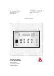
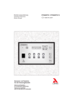
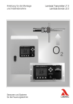
Fig. 1 shows the display and control unit for the lambda transmitter LT 2. It consists of
an LCD display, the cursor keys, the Enter key and the menu keys.
•
•
•
The cursor keys serve to select measured values, parameters or functions within
the display readout. The keys also position the cursor for Input and for Editing
(amendments).
The Enter key activates the editing mode and confirms and ends
The menu keys correspond to the menu item shown above them.
In Fig. 1, the menu keys have the following functions, from left to right:
Measurement [meas], Calibration [cal], Parameter setup [par], Diagnostics [diag].
The menu keys are identified by the LT 2 lambda transmitter's functions, in
abbreviated English form:
measurement, calibration, parameter setup, diagnostics
NOTE:
The limit values are only displayed if they were activated via parameters 930 / 940 /
950 / 960 ("Service” - level). See also chapter 5.
4
3 Display
3
Display
The display divides into three ranges (fig. 2):
1. The status line at the top margin. It shows:
• On the left side, if the maintenance mode is activated.
•
In the center the current operating condition.
•
On the right side, if warnings or faults are present.
•
Faults are indicated to the status line additionally by flashing.
2. The measured value representation in the center of the normal range.
3. The menu line, whose entry is assigned to the menu key present under it.
1
2
3
Figure 2
3.1
Menu function
Pressing the [meas] key switches the display to a large representation of the value
selected via the up/down cursor keys. Pressing the [meas] key repeatedly switches
the display back to a listing of all the measured values.
O2 output
21.0 Vol.%
5
3 Display
3.2
Menu function
By pressing the [cal] menu key calibration starts is shown on the display. After
activating the calibration, 4 calibration functions are available (see Fig. 1):
• Start the offset-calibration on ambient air
•
Start the offset-calibration with compressed air (during semi-automatic calibration,
open stop valve in the SAK)
•
Start the calibration via comparative measurement (during manual calibration
function) only if the O2 value is under 18 %.
•
Start the calibration with test gas (during semi-automatic calibration, open stop
valve in the SAK)
The required calibration function is selected via the up/down cursor keys. The ENTER
key confirms the selected function and triggers this calibration procedure.
The automatic calibration modes can be interrupted via the menu function Interrupt
calibration, return to measurement function.
During manual calibration, the calibrated value can be changed via the menu function
Change calibrated value (Fig. 2).
After calling up this menu function, the amendment procedure in the displayed
submenu can be terminated with the [cancel] key. Alternatively, the amended O2 value
can be accepted with the [OK] key.
Manual calibration is interrupted or ended with End calibration, return to measurement
function (the amended O2 value is preserved).
NOTE:
The Manual calibration mode remains active for a maximum of 15 minutes (this is the
factory setting). This is followed by switching back automatically to the measurement
mode. The maximum manual calibration time can be changed via parameter 288 at
service level.
A substitute O2 value is displayed during calibration procedures. Measurement or
display of a meaningful O2 value is only possible in the operational mode, i.e. after
completing the calibration.
6
3 Display
3.3
Menu function
After calling up the [par] menu, the menu opens up for the parameters.
Access to the parameter menu is divided into the following clearance levels:
•
Operational level
•
Customer level
•
Service level
•
Factory level
(only accessible via password)
NOTE:
The customer level password can be set freely by the customer.
The current clearance level is shown on the display. The available menu functions are
displayed in the menu bar:
3.4
•
[ exit ] returns to start menu.
•
[ psw ]
allows changing the clearance level via password input.
•
[ view ]
displays the parameter settings. All the parameters are displayed,
regardless of clearance level.
•
[ change ]
allows the changing of parameters: only the parameters accessible
at the clearance level are displayed.
Menu function
[psw] calls up the password input menu. The operational clearance level* is
displayed. The functions visible in the menu bar mean:
•
[ exit ] returns to the [par] menu.
•
[ clear ]
•
[ ---- ] shifts to the alphabetically previous input letter.
•
[ ++++ ] shifts to the alphabetically next input letter.
resets the clearance level to operational level*
The up/down cursor keys act similarly to [++++] and [----]. Left/right move the input
point along the password. Once the correct password is entered, the corresponding
clearance level is displayed and is retained on leaving the menu with [exit]. If no key
is pressed for some time, the clearance level is reset to the operational level.*
* If the customer clearance level is still at the factory setting, the customer level is set.
7
3 Display
3.5
Menu function
[ view ]
opens the parameter menu. The menu bar is interpreted as follows:
[ exit ]
returns to the menu function [par]
[ s/l ]
toggles between display formats:
Short: only the parameter number and the current value are displayed.
Medium: the parameter number and the current value are accompanied by a short
description.
Long: as Medium, but with an additional parameter status row displayed.
[ group - ] scrolls back one parameter group.
[ group+ ] scrolls forward one parameter group.
All available parameter groups are summarised in the appendix. The left/right cursor
keys correspond to the key-functions of:
[group -] and [group+] respectively.
If not all the parameters in a group are visible in the readout, this is indicated by
flashing arrows in the right-hand margin. The up/down cursor keys can be used to shift
the parameters and make them visible.
As an example, we explain below the status row shown in the Long format:
• *kw*_30_____[ 12 ; 42 ]_____
The asterisks and underline characters (* and _) are fillers.
•
K
indicates the customer clearance level
(b = operation, k = customer, s = service, f = manufacturing)
•
W
indicates the parameter type
(write = revisable, read = read only).
•
30
•
[ 12 ; 42 ] is the possible range within which the parameter can be changed
is the default value (base value in EPROM)
For some parameters there is no default value and interval!
8
3 Display
3.6
Menu function
[change] allows parameter values to be amended. The menu bar for the submenu is
the same as the [view] menu.
However, here the parameter to be changed is shown inverted (light characters on a
dark background). The required parameter can be selected via the up/down cursor
keys. The edit mode for that parameter is activated with the [ENTER] key. The
parameter's value flashes during editing.
Selected parameters are indicated in three ways:
→ parameter can be changed
→ parameter cannot be changes
→ active editing mode (change mode)
The parameter can now be changed via the up/down cursor keys (and left/right for
multidigit parameters). The menu bar functions are interpreted as follows:
•
[ esc ] returns to the [change] menu without accepting the changed
parameter.
•
[ dflt ] sets the default value.
•
[ OK ] accepts the changed value and returns to [ENTER] or [change]
menu.
This procedure leads back to the [change] menu. Further parameters can be called up
and changed.
9
3 Display
3.7
Menu function
On pressing the [diag] key, the display switches to show warnings and faults. The
up/down cursor keys can be used to select individual warnings or faults, or limit
values.
NOTE:
Limit values are only displayed if they were activated via parameters
930/940/950/960 (Service level).
The selected warning or fault, shown in reverse video, can now be acknowledged or
reset via the ENTER key.
NOTE:
Not all warnings or faults can be reset by means of an acknowledgement. The cause
of the warning or fault may need to be rectified first.
If a limit value is selected and then the ENTER key pressed, the display switches to
the limit value menu.
Explanation:Limit value 1 is parameterised to the O2 measured value
Switching points: Crossing upwards
10.0 Vol.% O2
Crossing downwards
3.0 Vol.% O2
Current O2 measured value 6.7 Vol.% O2
Limit value is not set.
Li 2
LI 3
- means: limit value 2 was triggered D to crossing downwards
- means: limit value 3 was triggered D to crossing upwards
The right/left cursor keys can now be used to select each limit value in succession.
As soon as reset mode "Manual” or "Acknowledge” has been selected, the limit value
can be reset via "Reset”.
Use "Exit” to leave the limit value menu.
10
4 Display Parameter
4
Display Parameter
4.1
Display Parameter 970 / 971 / 972
The parameter group ***Display*** controls the LT 2 lambda transmitter's Display and
Control unit, with the following parameters:
• P. 970
Contrast
•
This parameter serves to set the display contrast.
P. 971
Brightness
•
This parameter controls the display's background brightness.
P. 972
Language
The language of the output text (German, English) can be selected.
4.2
Brightness and contrast
Brightness and contrast can also be changed via the cursor keys, as follows:
Contrast +
→ Keys 1 & 2
Contrast -
→ Keys 3 & 4
Brightness +
→ Keys 1 & 4
Brightness -
→ Keys 2 & 3
Press the appropriate two keys simultaneously
11
4 Display Parameter
4.3
Customer password input
The password for the customer level can be selected individually by the customer. In
order to enter a new password, at least the customer clearance level must be
activated.
The new password must be entered as parameter 1472 (see Fig. below).
ATTENTION!
The password is accepted by the system a few seconds after input, and is displayed
as "####”. Thus, an entered password can never be read out.
NOTE:
The password is set to "0000” at the factory. Since this corresponds to the password
input default setting, the customer level can be activated by switching briefly to
password input and leaving it again without making any changes.
12
5 Limit values
5
Limit values
Measured data can be monitored with the help of limit values. The LT 2 lambda
transmitter comes with 4 fixed limit values as standard, that can be freely configured.
Load-dependent limit curves and fuel-specific limit values are available as option
657R0920.
Monitoring takes place by comparing the current value with a lower limit (Min.
comparison value) and with an upper limit (Max. comparison value).
If the monitored value falls outside the range (window), i.e. it is smaller than the Min.
comparison value or greater than the Max. comparison value, the limit value output is
set.
Parameters 910 to 914 indicate whether the limit value is set.
The limit values 1 - 4 can be used to switch the LT 2 transmitter's relay outputs. The
settings that need to be made are described in the chapter about digital outputs
(chapter 6). The limit value configurations, the display and resetting of limit values are
described below. When using the display, these items can be found in the parameter
groups limit value config. and limit values. The relevant parameter numbers are listed
in the Appendix, table in chapter 8.2 following.
5.1
Limit value configuration
Each of the 4 limit values has seven parameters, used for configuration (e.g. for limit
value 1):
1. Li 1 acts on (see 5.1.1)
2. 1: Max. comparison value (see 5.1.2)
3. 1: Min. comparison value (see 5.1.2)
4. 1: Const. Li Max. (see 5.1.1)
5. 1: Const. LiV Min. (see 5.1.3)
6. 1: Reset mode (see 5.1.4)
7. 1: Triggering delay (see 5.1.5)
The parameters are preceded by the number of their corresponding limit value.
13
5 Limit values
5.1.1
Limit value 1 (2,3,4) acts on (Parameters 930/940/950/960)
This parameters specifies which value is to be monitored. The following values are
available for monitoring:
5.1.2
•
Off - the limit value is not in currently in use
•
O2 measured value
•
Configurable values: one of 6 measured values definable by the user is being
monitored.
•
Probe's internal resistance
•
Probe voltage
Max. comparison value (Par. 931/941/951/961) / min. comparison value (Par. 932/942/952/962)
Three possible settings are available for the upper and lower comparison values:
Off:
Constant value:
Calculated analogue
value:
5.1.3
The comparison value is not activated.
A constant reference value is chosen to serve as a comparison value, see 5.1.1.
A value calculated from the actual O2 value or from an analogue input serves as a
reference value. In the LT 2 lambda transmitter, one of 12 available reference values
can be selected. Configuration of the analogue values to be calculated: see separate
Instructions.
Constant Li max. (Par. 933/943/953/963) / Constant Li min (Par. 934/944/954/964)
If a constant value is selected to serve as the reference value, this constant is stored
in Li Max. or Min. Please note that only integers can be entered. If the constant
reference value is displayed with decimal places, it should be entered without the
decimal point.
Example 1:
The measured O2 value needs to be monitored. The limit value output is set as
follows:
If dropping below 5.5% or exceeding 15.6 vol.% O2.
A constant value is specified for the Min. and Max. reference values:
- For the constant Li Max.: 156
- For the constant Li Min.: 55
NOTE:
If the measured value is to be monitored only for exceeding the maximum or only
dropping below the minimum, only the constant Li-max. and Li-min. has to be set.
Example 2:
The probe's voltage needs to be monitored. The voltage is shown on the display in
mV. The limit values should be specified as integers in mV. An input of 100
corresponds to 100 mV.
14
5 Limit values
5.1.4
Reset mode (Par. 935/945/955/965)
If the limit value is set as a result of the reference value being crossed (in either
direction), this parameter describes the limit value's resetting mode. Three possibilities
are available:
If the monitored value is changed so that once again it lies within the Li Min. and Li
Max. range, the limit value output is reset automatically to off.
Automatic:
Manual:
The limit value output must be reset manually via the display, via one of the digital
inputs or via the remote software(s. Limit values). In this resetting mode, limit values
can only be reset if the monitored value lies within the acceptable range.
Acknowledge:
The limit value output must be reset either manually via the display, via one of the
digital inputs or via the remote software (s.Limit values). If the monitored reference
value is still outside the acceptable range it is only acknowledged to begin with, and
disappears on entering the acceptable range.
Each individual limit value can be deactivated now over the function “Deakt. GWx”
over the digital inputs (x={1,2,3,4}).
5.1.5
Triggering delay (Par. 936/946/956/966)
This parameter can be used to set a triggering delay in the range 0 to 600 seconds.
The limit value output is only set if the monitored reference value lies outside the Li
Min. and Li Max. range for longer than the specified period. If the reference value is
once again within the Li Min. and Li Max. limits, the time counter is reset. The
triggering delay starts to count again from 0 when Li Min. or Li Max. is exceeded in the
relevant direction.
5.1.6
Disable limits (Par. 967)
All limits can be disable together depently of the operating mode.
Selections: Limits are disabled when
• 0=never
•
1=cold start (default)
•
2=cold start + maintenance
•
3=not measure
15
5 Limit values
5.2
Limit values display and resetting
The limit values' current status as well as resetting limit values, make use of the
display in the limit values group; the relevant parameter numbers are shown in the
Appendix, table in chapter 8.2.
Parameters 910 ... 914
The parameters limit value 1, limit value 2, limit value 3 and limit value 4 indicate the
limit values' current settings and status. Off means that either the corresponding limit
value is not in use, or the monitored reference value is within the limits Li Min. and Li
Max. If a limit value is shown as "set”, the monitored reference value is or was
outside those limits.
Parameters 914 ... 917
Resetting the limit value output proceeds with the help of the parameters Reset Li 1,
Reset Li 2, Reset Li 3 and Reset Li 4, provided that the manual or acknowledge reset
mode was selected. In order to reset a limit value, "Reset” must be entered in the
corresponding parameter. However, resetting in the manual mode is only possible if
the monitored reference value is within the limits Li Min. and Li Max.
16
5 Limit values
5.2.1
Display of the limit value crossing
Following activation of the limit value parameters 930/940/950/960 , "Service”
clearance level, the display shows Li1, Li2, Li3, Li4 depending on which limit value
has just been activated.
Crossing the limit value in either direction is shown as follows:
5.2.2
•
Li 1
•
Li 2
means limit value 1 has been crossed upwards
means limit value 2 has been crossed downwards
Calling up limit value settings
•
Press the "diag” (Diagnostics) key value settings
Use the cursor keys to select the appropriate limit value
The selected limit value is highlighted by a frame
↑
Limit value
selected
• Press the ENTER key
The limit value's current setting appears on the display, see illustration.
1. Limit value 1 is parameterised for the measured O2 value
2. Switching points:
Upward crossing
10.0 vol.% O2
Downward crossing
3.0 vol.% O2
3. Currently measured O2 value 6.7 Vol.% O2
4. Limit value not set. Possible states:
• Set → Limit value was triggered
•
Off → Measured value in acceptable range
•
Acknowloedged → Limit value crossing has already been acknowledged
17
5 Limit values
5.3
Load-dependent limit curves, fuel-specific limit values (option 657R0920)
Load-dependent limit curves,
The load value (burner load) or some other measured value is switched on via
analogue input 4. Instead of fixed limit values, fuel-specific curves of 2 to a maximum
of 8 checkpoints can be entered.
Limit curves (factory setting), with parameters set for crossing the lower threshold.
Possible combinations:
Either
- 2 fuels à 4 limit curves / limit values per fuel
or
- 4 fuels à 2 limit curves / limit values per fuel
5.3.1
2 fuels à 4 limit curves / limit values per fuel
Limit values 1 to 4 are used (Li 1 ... Li 4)
Allocation of limit curves / limit values
Curve
Function
Fuel
5
6
7
8
9
10
11
12
LiC1/Li1
LiC1/Li1
LiC2/Li2
LiC2/Li2
LiC3/Li3
LiC3/Li3
LiC4/Li4
LiC4/Li4
1
2
1
2
1
2
1
2
Calculated
analogue value
9
9
10
10
11
11
12
12
LiC = limit curve
Li = limit value
NOTE:
The analogue values indicated in the table are parameterized in such a way that they
calculate the monitoring threshold for the indicated limit value in dependence of the
fuel and the burner load. If the load-dependent limit values are to be activated again
e.g. for limit value 2, after meanwhile constant limit values were adjusted, parameter
942 (“reference value min.”) must be adjusted to the calculated analogue value 10,
shown above in the table. In place of monitoring an under-usage and monitoring of
an excess is wished, instead of parameter 942 parameter 941 must be adjusted
(comparison value max) to the calculated analogue value.
18
5 Limit values
5.3.2
4 fuels à 2 limit curves / limit values per fuel
Limit values 1 and 3 are used (Li 1 and Li 3)
Allocation of limit curves / limit values
Curve
Function
Fuel
5
6
7
8
9
10
11
12
LiC1/Li1
LiC1/Li1
LiC2/Li2
LiC2/Li2
LiC3/Li3
LiC3/Li3
LiC4/Li4
LiC4/Li4
1
2
3
4
1
2
3
4
Calculated
analogue value
9
9
9
9
11
11
11
11
LiC = limit curve
Li = limit value
5.3.3
Parameter setup (factory settings)
5.3.3.1 Analogue input 4
Par.
Par.
Par.
Par.
Par.
Par.
602:
603:
604:
605:
606:
607:
“Analogue input 4”
“Curve 4”
3,9 mA
20,1 mA
“Off”
“Off”
Display of the load value via configurable measured value 6
Par.
Par.
Par.
Par.
Par.
800:
801:
809 :
812:
813:
“Calc. Analogue value 4”
“Burner load”
“%”
“XXXX”
“0,4s”
Conversion 4...20 mA ^ 0...100% for load specification (burner load) via curve 4, as
follows:
Parameter
Value
2150
X1
4000 [4 mA]
2151
Y1
20 [20 %]
2152
X2
20000 [20 mA]
2153
Y2
100 [100%]
19
5 Limit values
5.3.3.2 Limit curves / Limit values
Parameter setup for the 4 limit curves takes place via the analogue calculations 9 to
12.
ATTENTION!
Fuel selection "Par. 836 Digital inputs” must be switched on.
Limit curve 1
Analogue calc. 9:
Par. 652: "Calculates analogue val. 4”
Par. 653: "Curve 5”
Par. 654: “Off”
Par. 657: “Curve +BS” (at manufacturing level)
Limit curve 2
Analogue calc. 10:
Par. 662: "Calculates analogue val. 4”
Par. 663: “Curve 7”
Par. 664: “Off”
Par. 667: “Curve +BS” (at manufacturing level)
Limit curve 3
Analogue calc. 11:
Par. 672: "Calculates analogue val. 4”
Par. 673: “Curve 9”
Par. 674: “Off”
Par. 677: “Curve +BS” (at manufacturing level)
Limit curve 4
Analogue calc. 12:
Par. 682: "Calculates analogue val. 4”
Par. 683: “Curve 11”
Par. 684: “Off”
Par. 687: “Curve +BS” (at manufacturing level)
If, instead of the limit curves, fixed limit values are to be specified, then parameters
930, 931, 940, 941, 950, 952, 960, 961 should be adjusted accordingly, see 4.1.1.2
and 4.1.1.3.
The following settings are made at the factory:
Limit value 1 / limit curve 1
Par. 930: "O2 measured value” or some other measured value to be monitored
Par. 931: "Off” (upper limit value)
Par. 932: "Calc. analogue value 9”
Par. 935: Resetting mode "Automatic”
Par. 936: Triggering delay to 0 seconds
Limit value 2 / limit curve 2
Par. 940: "O2 measured value” or some other measured value to be monitored
Par. 941: "Off” (upper limit value)
Par. 942: "Calc. analogue value 10”
Par. 945: Resetting mode "Automatic”
Par. 946: Triggering delay to 0 seconds
Limit value 3 / limit curve 3
Par. 950: "O2 measured value” or some other measured value to be monitored
Par. 951: "Off” (upper limit value)
Par. 952: "Calc. analogue value 11”
Par. 955: "Automatic” resetting mode
Par. 956: Triggering delay to 0 seconds
Limit value 4 / limit curve 4
Par. 960: "O2 measured value” or some other measured value to be monitored
Par. 961: "Off” (upper limit value)
Par. 962: "Calc. analogue value 12”
Par. 965: Resetting mode "Automatic”
Par. 966: Triggering delay to 60 seconds
20
5 Limit values
NOTE:
If the limit value 4 / limit curve 4 should not be needed, it is recommended to reparameterize these for the monitoring of the Lambda probe LS 2 on air value < -5 mV
= ≥.16 % volume O2.
For this the following parameter configuration has to be set:
Par.960: “LS2-voltage”
Par.961: “off“
Par.962: “constant value“
Par.964: -50 = -5 mV
Par. 965: “automatic“
Par. 966: Release delay 1 second
5.3.4
Input of limit values / limit curves
See also tables in 4.3.1 and 4.3.2
Factory settings - Direct triggering in the event of falling below these
values after a delay of 0 seconds
Limit curve 1 / Fuel 1
x1 --- x5
Burner load
y1 --- y5
O2 limit values (curves)
Max. 8 curve-points possible
Distribution can be freely chosen!
Parameter
2200
2201
2202
2203
2204
2205
2206
2207
2208
2209
X1
Y1
X2
Y2
X3
Y3
X4
Y4
X5
Y5
Value
20 [20 %]
30 [3.0 % O2]
40 [40 %]
25 [2.5 % O2]
60 [60 %]
20 [2,0 % O2]
80 [80 %]
18 [1,8 % O2]
100 [100 %]
15 [1,5 % O2]
Limit value curve 2 / Fuel 1
Parameter
2300
2301
2302
2303
2304
2305
2306
2307
2308
2309
X1
Y1
X2
Y2
X3
Y3
X4
Y4
X5
Y5
Value
20 [20 %]
25 [2.5 % O2]
40 [40 %]
20 [20 % O2]
60 [60 %]
15 [1.5 % O2]
80 [80 %]
10 [1.0 % O2]
100 [100 %]
5 [0.5 % O2]
21
6 Digital outputs (relays)
6
Digital outputs (relays)
6.1
Digital outputs for the control of the relay-modules
Up to 7 digital outputs can be freely configured in the LT 2 Lambda Transmitter. The
same parameters are available for the configuration of each digital output. These are:
• Idle state (see 5.1)
•
Four functions that trigger a switching procedure; the four functions are OR-ed
(see 5.2)
•
Display of the current relay position (see 5.3)
Factory assignment of the digital outputs
Output 1 → Collecting faults
Output 2 → Warning / maintenance
Output 3 → Measurement
Output 4 → limit value 1
Output 5 → limit value 2
Output 6 → limit value 3
Output 7 → limit value 4
6.2
Idle state
This is where the idle state is set. This state is present if none of the four functions
triggers a switching procedure. The setting Diagnostic operation allows the idle state
to be changed via the parameter Position (see below).
Parameters:
1030/1040/1050/1060
•
LOW (open circuit principle)
•
HIGH (closed circuit principle)
•
Diagnostic operation
22
6 Digital outputs (relays)
6.3
Function A,B,C,D
The four functions are structured almost identically; an operational state can serve as
a switching criterion. If a Limit value (Li 1-4) is selected as a switching criterion, the
Parameters: 1031 to 1034 output switches if the limit value's output is set. Maintenance is chosen as a switching
1041 to 1044 criterion, the output is not in the idle state during maintenance.
1051 to 1054
1061 to 1064 Each function (A, B, C, D) can have all operational states as the switching criterion;
however, the allocation of limit values Li 1-4 and/or test gases is restricted to individual
functions. Limit value 1 and Test gas 1 are only possible with Function A,
analogously Limit value 2 and Test gas 2 with Function B etc. However, all
combinations can be set by OR-ing the four functions.
The following operational states can be selected as switching criteria:
• Off
6.4
•
Warning
•
Fault
•
Calibration
•
Checking
•
Cold start
•
Measurement
•
Standby
•
Maintenance
•
Limit values 1 – 4
•
Probe 1
•
No measurement
Position
Parameters:
1039/1049/1059/1069
This parameter indicates the current switching state. Manual switching of the output is
possible by changing the parameter via diagnostic operation.
23
7 Digital inputs
7
Digital inputs
8 digital inputs can be configured for the LT 2 Lambda Transmitter. The inputs switch
position according to the applied voltage: High (applied voltage 24 V) or Low (input
open or voltage 0 V).
Depending on this position, the LT 2 transmitter can carry out certain actions. All 8
digital inputs are identical with regard to structure and functionality. The inputs'
configuration is controlled by the following parameters:
Factory assignment of the digital inputs
• Input 1 → Reset warning / fault
•
Input 2 → Reset limit value message
•
Input 3 → Offset calibration
•
Input 4 → Not configured
•
Input 5 → Not configured
•
Input 6 → (1) Fuel 2 (gas)
•
Input 7 → (1) Fuel 3
•
Input 8 → (1) Fuel 4
(1) Parameter 836 Service level must be set to “Digital inputs” .
If no signal preset → Heating oil EL.
7.1
Idle state
Parameters:
1170/1180/1190/1200/
1210/1220/1230/1240
This is where the digital inputs idle state is set. If the position differs from that set here,
the actions specified by the functions (A, B, C, D) is carried out. If Diagnostic
operation is set here, the functions (A, B, C, D) can be triggered for the appropriate
digital input via the parameter Position.
•
LOW (open circuit principle)
•
HIGH (closed circuit principle)
•
Diagnostic operation
24
7 Digital inputs
7.2
Function A,B,C,D
The four functions are structured almost identically. However, the allocation of limit
values Li 1-4 and/or fuels is restricted to the individual functions
(A, B, C, D). Resetting of limit value 1 and Fuel 1 are only possible with function A;
analogously, resetting of limit value 2 and test gas 2 only with function B, and so on.
The following actions are possible:
• None
7.3
•
Offset calibration
triggers an offset calibration
•
Fault rese
acknowledges present faults
•
Warning reset
acknowledges present warnings
•
Reset Li 1
(function A) resets limit value 1; functions B, C, D reset
limit values 2, 3, 4
•
Fuel 1
(only function A) selects fuel 1; functions B, C, D select
fuels 2, 3, 4
•
Probe 1
(only function A) selects probe 1; functions B, C, D select
probes 2, 3, 4
•
No cal.
calibration locked
•
PID control unit on / off provided the PID control unit option is activated,
this function allows the PID control unit to be
turned off.
•
Maintenance
triggers the device to maintenance
•
Deactivate
limit value x (see chapter 5.2)
Status
Parameters:
1175/1185/1195/1205/
1215/1225/1235/1245
This parameter indicates the digital input's state.
The three possible states are inactive (idle state) and active; the set functions (A, B, C,
D) are triggered.
The digital input's state can be set manually with this parameter, provided the
parameter Idle level is set to Diagnostic operation.
25
8 Appendix
8
Appendix
8.1
Parameters associated with digital inputs
Parameter group digital input 1, 2, 3
Parameter number
Description
1170, 1180, 1190, …
Idle level, digital input 1, 2, 3,… (0 = low, 1 = high, 2 = Diagnostic
operation)
variable
1171, 1181, 1191,…
1172, 1182, 1192, …
1173, 1183, 1193,…
1174, 1184, 1194,…
1175, 1185, 1195,…
Access
Function A, B, C, D of digital input 1, 2, 3, 4
0 = None
6 = Reset Li1 / Li2 / Li3 / Li4
1 = Offset calibration
7 = Fuel 1 / 2 / 3 / 4
2 = Testgas cal.
8 = No calibration (blocked)
3 = Faults reset
9 = PID control unit off
4 = Warning reset
10 = maintenance
5 = Probe 1/ 2/ 3 /4
11 = deactivate Li1/Li2/Li3/Li4
State of digital input 1,2,3,... (0=Off, 1=Active)
26
variable
variable
8 Appendix
8.2
Parameters associated with limit values
Parameter number
Description
Access
910
911
912
913
914
915
916
917
Display of state of limit value 1, 0 = Off, 1 = Active
Display of state of limit value 2, 0 = Off, 1 = Active
Display of state of limit value 3, 0 = Off, 1 = Active
Display of state of limit value 4, 0 = Off, 1 = Active
Manual reset of limit value 1, set to 1 for resetting
Manual reset of limit value 2, set to 1 for resetting
Manual reset of limit value 3, set to 1 for resetting
Manual reset of limit value 4, set to 1 for resetting
read only
read only
read only
read only
variable
variable
variable
variable
Parameter number
Description
Access
930 (940, 950, 960)
Selection of the monitored quantity for limit value 1 (2, 3, 4)
0 = None, 1 = O2 value, 2...7 = configurable measured value 1
[sic].7, 8 = LS1 temperature, 9 = LS1 pressure, 10 = LS1 current,
11 = LS1 voltage
Form for comparison value Max with Li 1 (2, 3, 4)
0 = Off, 1 = Const. value, 2...13 = Calculated analogue value
1...12
Form for comparison value Min with Li 1 (2, 3, 4)
0 = Off, 1 = Const. value, 2...13 = Calculated analogue value
1...12
Constants for comparison value Max with Li 1 (2, 3, 4)
(only with 931, 941, 951, 961 = fixed value) variable
variable
Parameter group limit value configuration
931 (941, 951, 961)
932 (942, 952, 962)
933 (943, 953, 963)
934 (944, 954, 964)
935 (945, 955, 965)
936 (946, 956, 966)
967
8.3
Constants for comparison value Min with Li 1 (2, 3, 4)
(only with 932, 942, 952, 962 = fixed value) variable
variable
variable
variable
variable
variable
Reset mode for limit value 1 (2, 3, 4)
0 = Automatic, 1 = Manual, 2 = Acknowledge
Triggering delay for limit value 1, 2, 3, 4 (in sec)
Operational mode deactivate limit value
variable
variable
Parameters associated with digital outputs
Parameter group digital output 1 (2, 3, …, 7)
Parameter number
1030, 1040, 1050,…
1031, 1041, 1051,…
1032, 1042, 1052,…
1033, 1043, 1053,…
1034, 1044, 1054,…
1039, 1049, 1059,…
Description
Clearance for Access
Idle level
0 = Down, 1 = Up, 2 = Diagnostic operation
Function A
0 = Off, 1 = Warning, 2 = Fault,
3 = Calibration, 4 = Check, 5 = Cold start,
6 = Measurement, 7 = Standby,
8 = Maintenance, 9 = Li 1, 10 = Probe 1,2,3,4,
11 = No measurement
Function B
As function A, but 9 = Li 2, 10 = Probe 2
Function C
As function A, but 9=Li 3, 10=Probe 3
Function D
As function A, but 9=Li 4, 10=Probe 4
Actual position (changeable in diagnostic mode)
0 = secede, 1 = tightened
27
Service
variable
Service
variable
Service
variable
Service
variable
Service
variable
Service
variable
8 Appendix
8.4
Parameter groups
Test datas
from par 1
Relay 1
from par 1030
Operational data
from par 40
Relay 2
from par 1040
Counters and times
from par 70
Relay 3
from par 1050
Commands
from par 108
Relay 4
from par 1060
Hardware options
from par 120
Relay 5
from par 1070
LS2 Calibration data
from par 140
Relay 6
from par 1080
LS2 Probe heating
from par 180
Relay 7
from par 1090
Probe selection
from par 200
Digital input 1
from par 1170
LS2 Monitoring
from par 210
Digital input 2
from par 1180
Probe heating Ri supervision
from par 220
Digital input 3
from par 1190
Cold start
from par 230
Digital input 4
from par 1200
LS2 Calibration
from par 270
Digital input 5
from par 1210
O2 meas.value config.
from par 360
Digital input 6
from par 1220
COe meas.value config.
from par 370
Digital input 7
from par 1230
Monitor output
from par 380
Digital input 8
from par 1240
Reference air
from par 390
Service times
from par 1260
Absolute pressure
from par 410
Bus interface
from par 1300
Pressure compensation
from par 420
LS2 Dynamic monitoring
from par 1330
Temperature compensation
from par 450
PID Control unit
from par 1350
Modbus RS232
from par 480
PID Control unit config.
from par 1361
Analogue output 1
from par 530
PID Control unit status
from par 1380
Analogue output 2
from par 540
Password/serial no.
from par 1472
Analogue output 3
from par 550
Parameter CRC 16
from par 1490
Analogue output 4
from par 560
Probe data
from par 1500
Analogue input 1
from par 570
Faults history
from par 1900
Analogue input 2
from par 580
Curve 1
from par 2000
Analogue input 3
from par 590
Curve 2
from par 2050
Analogue input 4
from par 600
Curve 3
from par 2100
Analogue calculation 5
from par 610
Curve 4
from par 2150
Analogue calculation 6
from par 620
Curve 5
from par 2200
Analogue calculation 7
from par 630
Curve 6
from par 2250
Analogue calculation 8
from par 640
Curve 7
from par 2300
Analogue calculation 9
from par 650
Curve 8
from par 2350
Analogue calculation 10
from par 660
Curve 9
from par 2400
Analogue calculation 11
from par 670
Curve 10
from par 2450
Analogue calculation 12
from par 680
Curve 11
from par 2500
Measured value config.
from par 700
Curve 12
from par 2550
Fuel config.
from par 835
CO-curve
from par 3600
Limit values
from par 910
Temperature statistic
from par 3750
Limit value config.
from par 930
LAMTEC SYSTEM BUS
from par 3800
Display
from par 970
Software version
from par 985
28
29
June 2005
Lamtec
meas
cal
par
20.9 Vol. %
0.0 mV
100 °C
25 °C
0.0 %
0.0 %
0.1 Ohm
20.9 Vol. %
exit
Status of calibration:
Offset
Break calibration before
end!
*** Calibration ***
O2 - Output
Probe Voltage
T-Exhaust gas
T-Intake air
Efficiency
Exhaustgas lo
Probe Ri
O2-Internal
Measurement
meas
diag
ENTER
20.9
O2-Output [Vol.%]
Measurement
exit
exit
ENTER
clear
-
+
ENTER
*** Test data ***
psw
LS 2 O2 - Output
P. 001:
20.9 %
LS 2 probe voltage
P. 002:
20.9 mV
LS 2 absolute pressure
P. 004:
0 mbar
exit
Operation level
**** Parameter Setup ****
par
LT 2 MENU OVERVIEW
**** Enter Password ****
SN: 000108LA - 11328
0 * * *
Released customer level
Offset-calibration
Offset-calibration on
on
ambient
ambient air
air
Offset-cal.
Offset-cal. with
with compressed
compressed
air,
air, open
open before!
before!
Calibration/test
Calibration/test with
with
reference-measuring
reference-measuring
Calibration/test
Calibration/test with
with testtestgas
gas open
open gas!
gas!
*** Calibration ***
cal
ENTER
Measure
esc
dflt
OK
ENTER
P 0001 - 0016
P 0046 - 0056
P 0070 - 0072
P 0360
P 0713 - 0813
P 0910 - 0917
P 0970 - 0972
P 0985 - 0990
P 1301
P 1490 - 1493
Operation-Level
s/l
ENTER
Measured values
Operating data
Counter & Timer
O2 value configuration
Meas. value configuration
Limits
Display
Software version
BUS-Interface
Parameter CRC 16
*** Display ***
Contrast
P. 970:
30
Brightness
P. 971:
10
Language
German
P. 972:
exit
view
Probe impedance limit
*** Warnings ***
diag
ENTER
group -
group +
ENTER
Measured values
Operating data
Counter & Timer
Commands
Flue gas pump
LS1 check
LS1 calibration
Test gases
O2 value configuration
MEV-Heating
Pressure measurement
Analog output 1
Analog output 2
Analog output 3
Analog output 4
Analog input 1
Analog input 2
Analog input 3
Analog input 4
Analog calculation 5
Analog calculation 6
Analog calculation 7
Analog calculation 8
Analog calculation 9
Analog calculation 10
Analog calculation 11
Analog calculation 12
Meas. value configuration
Fuel configuration
Limits
Limits configuration
Display
Software version
Digitaler input 1
Digitaler input 2
Digitaler input 3
Digitaler input 4
Digitaler input 5
Digitaler input 6
Digitaler input 7
Digitaler input 8
Service time
LS1 linearising
BUS-Interface
LS1 dynamic check
Password / Serial no.
Parameter CRC 16
Probe data
Calibration history 1-10
Table Ri LS1
Curve 1-12
P 0001 - 0016
P 0040 - 0056
P 0070 - 0072
P 0104 - 0105
P 0183
P 0250
P 0270 - 0288
P 0330 - 0345
P 0360 - 0362
P 0400 - 0403
P 0441 - 0442
P 0532 - 0534
P 0542 - 0544
P 0552 - 0554
P 0562 - 0564
P 0570 - 0578
P 0580 - 0588
P 0590 - 0598
P 0600 - 0608
P 0610 - 0618
P 0620 - 0628
P 0630 - 0638
P 0640 - 0648
P 0650 - 0658
P 0660 - 0668
P 0670 - 0678
P 0680 - 0688
P 0713 - 0813
P 0835
P 0910 - 0917
P 0933 - 0966
P 0970 - 0972
P 0985 - 0990
P 1175
P 1185
P 1195
P 1205
P 1215
P 1225
P 1235
P 1245
P 1260 - 1261
P 1280 - 1281
P 1300 - 1318
P 1330 - 1331
P 1472
P 1490 - 1493
P 1500 - 1563
P 1600 - 1793
P 1800 - 1898
P 2000 - 2565
Customer-Level
change
*** Faults ***
Error analog outputs
ENTER
Rev. 1v29
P 0001 - 0016
P 0040 - 0056
P 0070 - 0072
P 0104 - 0110
P 0121 - 0124
P 0140 - 0142
P 0150
P 0183 - 0190
P 0204
P 0250 - 0252
P 0270 - 0288
P 0330 - 0345
P 0360 - 0362
P 0380 - 0383
P 0400 - 0403
P 0441 - 0442
P 0480 - 0483
P 0530 - 0564
P 0570 - 0608
P 0610 - 0688
P 0700 - 0813
P 0835 - 0899
P 0910 - 0917
P 0930 - 0966
P 0970 - 0972
P 0985 - 0990
P 1030 - 1099
P 1109 - 1129
P 1170 - 1245
P 1260 - 1261
P 1280 - 1283
P 1300 - 1318
P 1330 - 1334
P 1472
P 1490 - 1493
P 1500 - 1563
P 1600 - 1793
P 1800 - 1898
P 1900 - 1978
P 2000 - 2565
Service-Level
Measured values
Operating data
Counter & Timer
Commands
Hardware options
LS 1 glide voltage
LS 1 probe heating
Flue gas pump
Normal cold start
LS1 check
LS1 calibration
Test gases
O2 value configuration
Monitor output
MEV-Heating
Pressure measurement
Modbus RS 232
Analog output 1 - 4
Analog input 1 - 4
Analog calculation 5 - 12
Meas. value configuration
Fuel configuration
Limits
Limits configuration
Display
Software version
Relay 1 - 7
Solenoid valves
Digital input 1 - 8
Service time
LS1 linearising
BUS-Interface
LS1 dynamic check
Password / Serial no.
Parameter CRC 16
Probe data
Calibration history 1 - 10
Table Ri LS1
Fault history
Curve 1 - 12
ENTER
8 Appendix
LAMTEC Meß- und Regeltechnik
für Feuerungen GmbH & Co KG
LAMTEC Leipzig GmbH & Co KG
Impexstraße 5
D-69190 Walldorf
Telefon (+49) 06227 / 6052-0
Telefax (+49) 06227 / 6052-57
Internet: http://www.lamtec.de
e-mail: [email protected]
Schlesierstraße 55
D-04299 Leipzig
Telefon (+49) 0341 / 863294-00
Telefax (+49) 0341 / 863294-10
Überreicht durch:
Druckschrift-Nr.: D LT 6060.05 aE - 0021
Printed in Germany