1
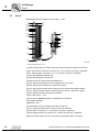
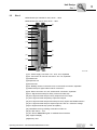
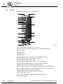
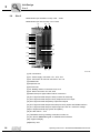
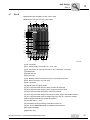
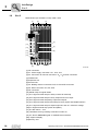
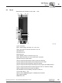
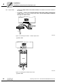
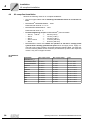
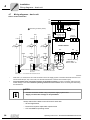
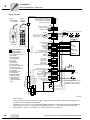
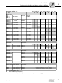
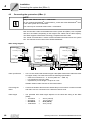
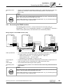
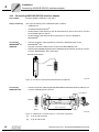
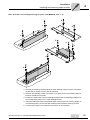
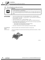
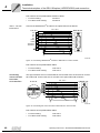
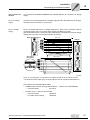
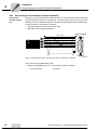
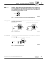
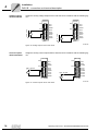
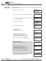
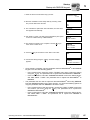
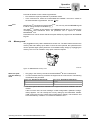
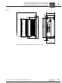
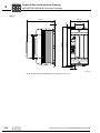
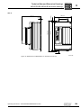
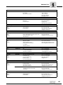
Installation
Connecting the system bus (SBus 1)
4
4.9
Connecting the system bus (SBus 1)
NOTE
Only if P884 "SBus baud rate" = 1000 kbaud:
Do not combine MOVIDRIVE® compact MCH4_A units with other MOVIDRIVE® units
in the same system bus combination.
The units may be combined at baud rates ≠ 1000 kbaud.
Max. 64 CAN bus nodes can be addressed via the system bus (SBus). Use a repeater
after 20 or 30 stations, depending on the length of the cables and the cable capacity.
The SBus supports transmission technology compliant with ISO 11898.
The "Serial Communication" manual contains detailed information about the system
bus. This manual can be ordered from SEW-EURODRIVE.
SBus wiring diagram
Control unit
S 11
S 12
S 13
S 14
Systembus
Terminating resistor
Control unit
ON OFF
Systembus
Ref.
Systembus High
Systembus Low
Control unit
1
2
3
Systembus
Ref.
Systembus High
Systembus Low
ON OFF
X12:
DGND
SC11
SC12
S 11
S 12
S 13
S 14
Systembus
Terminating resistor
ON OFF
X12:
DGND
SC11
SC12
S 11
S 12
S 13
S 14
Systembus
Terminating resistor
1
2
3
Systembus
Ref.
Systembus High
Systembus Low
X12:
DGND
SC11
SC12
1
2
3
54534AEN
Cable specification
•
Use a 4-core twisted and shielded copper cable (data transmission cable with braided copper shield). The cable must meet the following specifications:
– Cable cross section 0.25 ... 0.75 mm2 (AWG 23 ... AWG 19)
– Line resistance 120 Ω at 1 MHz
– Capacitance per unit length ≤ 40 pF/m at 1 kHz
Suitable cables include CAN bus or DeviceNet cables.
Connecting the
shield
•
Connect the shield to the electronics shield clamp on the inverter or master controller
and make sure it is connected over a wide area at both ends.
Cable length
•
The permitted total cable length depends on the baud rate setting of the SBus
(P884):
–
–
–
–
48
125 kbaud
250 kbaud
500 kBaud
1000 kbaud
→
→
→
→
320 m (1050 ft)
160 m (525 ft)
80 m (260 ft)
40 m (130 ft)
Operating Instructions – MOVIDRIVE® MDX60B/61B Inverter