1
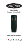
CR-R880-BL:
Indoor/Outdoor Proximity Reader
with 10cm (4in) read range
Installation Manual
Table of Contents
Basic Operation ...............................................2
CR-R880-BL Block Diagram ...................................2
Technical Specifications .................................3
Features ............................................................4
Tricolour LED Display .............................................4
Face Light ...............................................................4
Audible Tone ..........................................................5
Weather Resistant ..................................................5
SwiftRead ...............................................................5
Diagnostic Test .......................................................5
Installation ........................................................5
Important Notes on Selecting an Installation Site ...5
Mounting .................................................................6
Mounting on Metal ..................................................7
Wiring .....................................................................7
Card Presentation Test ...........................................8
Wiegand Output Wiring Diagram ..........................10
ABA Output Wiring Diagram .................................11
Dimensions ....................................................12
Regular Mounting Plate ........................................12
Gang Box Mounting Plate .....................................13
CR-R880-BL 1
Basic Operation
When power is supplied to the reader, the antenna in the
reader will emit a continuous low-frequency RF field.
When a card is placed within this field, the antenna inside
the card will gather the energy present in the field to
power the internal circuitry of the card. The card will then
transmit its unique identification (ID) number to the
Indoor/Outdoor Proximity Reader with 10cm (4in) read
range (CR-R880-BL). After receiving the signal, the
reader verifies the validity of the signal. If the signal is
valid, it will be decoded by the reader and sent in the
appropriate output format to the host controller through
data cables. The controller then determines what action
to take in response to the information received from the
reader.
Figure 1: CR-R880-BL Block Diagram
2 Installation Manual
Technical Specifications
Input Voltage:
Input Current:
Power Consumption:
Read Range*:
Frequency:
Operating Temperature:
Output Formats:
Cable Distance:
Recommended Cables:
Led Indicator:
Face Light:
Audio Indicator:
Colour:
Weight:
Material:
Typical 13.8Vdc
Minimum 11.0Vdc
Maximum 14.5Vdc
Typical 65mA @ 12.5Vdc
With card present 105mA @
12.5Vdc
Typical 812mW @ 12.5Vdc
With card present 1.31W @
12.5Vdc
CR-R702-A Clam Shell Card
CR-R704-B Blue Proximity Key Tag
Exciter field 125 KHz Pulse
Modulated
Receive Low Frequency 12.500
KHz
Receive High Frequency 15.625
KHz
Minimum -35°C (-31°F)
Maximum +65°C (149°F)
26-Bit Wiegand, 37-Bit Wiegand,
ABA & Custom
152.4m (500 feet)
22AWG (.8mm Dia.), MultiConductor, Alpha 5196, 5198
18AWG (1.2mm Dia.), MultiConductor, Alpha 5386, 5388
Belden 9553 (18AWG, 6 conductor,
stranded with overall shield)
Tricolour LED Display
Blue
Beeper
Black
9.8 oz. (280g)
UV resistant, ABS plastic
CR-R880-BL 3
Dimensions:
5.75" H x 2" W x 1" T
Gang Box Mounting Plate: Single (available as an option)
Approvals:
Compliant to all EU and EFTA
countries except Greece according
to RTT&E directives.
*The specified read range assumes no electrical
interference and that the card is presented parallel to
the reader, with the reader installed and operated as
outlined in this manual. The read range will vary
depending on the type of card used. The larger the
card, the greater the read range. The read range may
decrease if reader is mounted on metal.
All specifications are subject to change without
notice.
Features
Tricolour LED Display
The CR-R880-BL reader includes a tricolour LED display
(red, green and amber) used to indicate the reader's
status. When the orange wire is pulled low, the red LED
will illuminate. When the yellow wire is pulled low, the
green LED will illuminate. When the yellow and orange
wires are pulled low (oscillation at 1KHz is required), both
LEDs will illuminate producing an amber colour.
Face Light
The CR-R880-BL’s elegant blue face light remains
illuminated at all times so that it can be easily located in
the dark.
4 Installation Manual
Audible Tone
The CR-R880-BL reader includes a built in beeper that
will emit a tone every time the brown wire is pulled low.
Weather Resistant
Mount indoors or outdoors.
SwiftRead
After presenting the card, regardless of the card's access
status, the LED will flash to indicate that the reader has
read the card and the data was sent to the controller.
After the SwiftRead period, the controller resumes
control of the LED as usual.
Diagnostic Test
All CR-R880-BL readers perform a self-diagnostic test to
ensure proper operation at start-up and verify the
integrity of the data lines. Every time power is applied to
the reader, the green LED will flash twice to indicate the
diagnostic test was performed and no problems were
found. If the reader determines a problem after
performing the diagnostic test, the green and red LEDs
will toggle on and off and the beeper will emit a pulsing
tone.
Installation
Important Notes on Selecting an Installation Site
Please consider the following when installing the CRR880-BL card reader:
1. Avoid wiring the CR-R880-BL cables in the same
conduit with AC power cables, lock power, or signal
wiring.
CR-R880-BL 5
2. Maintain all reader wiring a minimum of 30 cm(12")
away from other wiring such as: AC power, computer
data wiring, telephone wiring, wiring to electric lock
devices, etc.
3. Avoid installing within 1.1m (3.5 feet) of computer
monitors or CRTs. The minimum distance will vary
depending on the type of monitor or CRT.
4. Avoid installing in proximity to sources of broad
spectrum EMI noise such as: motors, pumps,
generators, DC to AC converters, uninterruptible
power supplies, AC switching relays, light dimmers,
computer monitors and CRTs.
5. Avoid installing in proximity to potential sources of RF
signal transmitters such as: cellular telephones, two
way radios, etc.
Mounting
After selecting the appropriate mounting position for the
reader, use the reader's mounting-plate (refer to
page 12) as a guide and drill two mounting holes and a
3/8" to 1" hole for the reader cable. If you wish to mount
the CR-R880-BL on a gang box, a single gang box
mounting plate (CR-MTPLATE) is available as an option
(refer to page 13). Place a grommet around the edge of
the hole for the reader cable. At the reader end, prepare
the cable by cutting the cable jacket back 1-¼" and
stripping the wires ¼". After wiring the cables as
described below, screw the mounting plate onto the
selected installation site, snap the reader onto the
mounting plate and affix with a screw as shown on
page 12.
6 Installation Manual
Mounting on Metal
Although metal may decrease the read range, the CRR880-BL card reader can be mounted on metal.
However, do not box in or surround the card reader with
any kind of metal. If the reader must be installed in a
metal enclosure, ensure that the face of the card reader
is not covered and that there's at least 4cm (1.6")
between the card reader and the metal on all sides of the
card reader.
Wiring
Using the recommended cables listed in the technical
specifications on page 3, splice these cables together
with the pigtail of the reader and seal the splice. Route
the cable from the reader to the host controller. Do not
wire the CR-R880-BL cables in the same conduit with AC
power cables, lock power, or signal wiring. Maintain all
reader wiring a minimum of 30cm (12") away from other
wiring such as: AC power, computer data wiring,
telephone wiring, wiring to electric lock devices, etc.
Connect the cables as shown in Figure 2 on page 10 for
Wiegand connections, or Figure 3 on page 11 for ABA
connections. Trim and cover all conductors.
Important Installation Notes
Do not connect the shield wires together at
the reader cable splice. With the shield wire
already terminated at the reader, simply
terminate the shield at the controller. Do not
connect the shield to the black wire at the
reader cable splice. (refer to Figure 2 on
page 10 and Figure 3 on page 11).
CR-R880-BL 7
• LED and "beeper" operations are programmed via the
Centaur Access Control Software, if using another
controller refer to appropriate instructions.
• Do not use "twisted pair" with either output format.
• Pull the orange wire low to illuminate the red LED.
• Pull the yellow wire low to illuminate the green LED.
• Pull both the orange and yellow wires low to illuminate
the red and green LEDs, producing an amber colour
(an oscillation of 1KHz is required).
• Pull the brown wire low to activate the "beeper".
• Follow the recommended cable types and lengths,
listed in the technical specifications on page 3.
• For open collector (non-terminated output), consult
your system manufacturer for correct cable length and
type.
• The data out internal circuit configurations are as
shown below.
Card Presentation Test
Place the card parallel to the CR-R880-BL reader and
move it toward the reader until the card code displays on
the controller screen. At this point, the card is read,
decoded, data transmitted to the controller and the
8 Installation Manual
controller has responded accordingly. To read the card
again, remove and re-insert the card into the reader's
field.
CR-R880-BL 9
Figure 2: Wiegand Output Wiring Diagram
10 Installation Manual
Figure 3: ABA Output Wiring Diagram
CR-R880-BL 11
Dimensions
Figure 4: Regular Mounting Plate
12 Installation Manual
Figure 5: Gang Box Mounting Plate
CR-R880-BL 13
Warranty
Paradox Security Systems Ltd. (“Seller”) warrants its products to be free
from defects in materials and workmanship under normal use for a period of
one year. Except as specifically stated herein, all express or implied
warranties whatsoever, statutory or otherwise, including without limitation,
any implied warranty of merchantability and fitness for a particular purpose,
are expressly excluded. Because Seller does not install or connect the
products and because the products may be used in conjunction with
products not manufactured by Seller, Seller cannot guarantee the
performance of the security system and shall not be responsible for
circumstances resulting from the product’s inability to operate. Seller
obligation and liability under this warranty is expressly limited to repairing or
replacing, at Seller's option, any product not meeting the specifications.
Returns must include proof of purchase and be within the warranty period.
In no event shall the Seller be liable to the buyer or any other person for any
loss or damages whether direct or indirect or consequential or incidental,
including without limitation, any damages for lost profits stolen goods, or
claims by any other party, caused by defective goods or otherwise arising
from the improper, incorrect or otherwise faulty installation or use of the
merchandise sold.
Notwithstanding the preceding paragraph, the Seller’s maximum liability will
be strictly limited to the purchase price of the defective product. Your use of
this product signifies your acceptance of this warranty.
BEWARE: Dealers, installers and/or others selling the product are not
authorized to modify this warranty or make additional warranties that are
binding on the Seller.
© 2002-2005 Paradox Security Systems Ltd. All rights reserved.
Specifications may change without prior notice. One or more of the following
US patents may apply: 6215399, 6111256, 5751803, 5721542, 5287111,
5119069, 5077549, 5920259, 5886632. Canadian and international patents
may also apply.
Centaur is a trademark or registered trademark of Paradox Security
Systems Ltd. or its affiliates in Canada, the United States and/or other
countries.
14 Installation Manual
NOTES
780 Industriel Blvd., Saint-Eustache (Quebec) J7R 5V3 CANADA
Tel.: (450) 491-7444
Fax: (450) 491-2313
www.paradox.ca
PRINTED IN CANADA - 05/2005
CR880-EI06