1
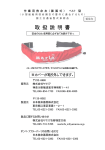
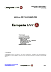
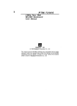
installation,
operating and
maintenance manual
datatech
6÷170 KW
Precision air conditioners
for technological environments
> DATATECH /EDA
Air cooled air-conditioner
> DATATECH /EDW
Water cooled air-conditioner
> DATATECH /EDA DC
Dual-Cooling mode air cooled air-conditioner
> DATATECH /EDW DC
Dual-Cooling mode water cooled air-conditioner
> DATATECH /EDW FC
Free-Cooling mode water cooled air-conditioner
> DATATECH /CW
Water cooled air-conditioner
> DATATECH /DW
Air-conditioner with double chilled water coil
4
Installation, use and maintenance manual Datatech
1. Field of application
Introduction
2. Inspection, unpacking, transport
Inspection
Unpacking
Lifting and transportation
3. Limitations on use
4. Safety precautions
Delimitation of danger zone
Safety rules
Refrigerant R410A - Safety Data Sheet
Installation in explosive atmosphere
Safety devices
Lighting
Qualification of personnel - obligations
Various instructions
5. Positioning
6. Installation
Clearance areas
Base frame ( UNDER Version)
Connection to the remote condenser
Connecting the pipes
Table 1 - Recommended diameters
Table 2 - Cooling capacities for units with circuit in separate sections
Table 3 - Additional cooling capacities R410A
Table 4 - Configurations
Table 5 - Friction loss and flow velocity in the piping system
Vacuum and charging the cooling system
Safety valves discharge line
Hydraulic connections
Connections to the plate condenser
Connections to the chilled water coil
Connection to the condensate drain
Connection to the hot water coil
Connection to the humidifier (HH version)
Wiring
General instructions
Alarms and external controls
Connection to the remote condensers
7. Operation
Preliminary checks
08
08
08
08
08
08
10
10
10
11
12
14
14
14
14
14
15
16
16
16
17
17
17
18
18
18
19
21
22
22
22
22
23
23
23
24
24
24
24
25
25
Datatech
index
5
8.
9.
10.
11.
Start-up
Checks during operation
Fans
Air filters
Humidifier
Control and safety devices
High pressure regulator
High pressure alarm (from pressure transducer)
Low pressure regulator
Compressor thermal protection
Phase sequence relay
Fans thermal protection
Air flow sensor
Dirty filter sensor (optional)
Fans differential air flow /differential pressure
Ambient humidity and temperature set points
Anti-recirculation timer
Maintenance and periodic checks
Warnings
General remarks
Refrigerant circuit divisions
Environmental considerations
Decommissioning the unit
Troubleshooting
ANNEXES
Electrical diagram
Microprocessor control
6
Installation, use and maintenance manual Datatech
25
25
26
26
27
28
28
28
28
28
28
29
29
29
30
30
30
31
31
31
32
32
33
33
La serie di gruppi refrigeratori e pompe di calore KAPPA V ENERGY è disponibile in varie grandezze con potenzialità
che variano ida
344 a 1541
kW (reseed
riferite
una temperatura
ingresso/uscita
acqua 12/7
°C, temperatura
tteristiche costruttive,
modelli
disponibili
i datiadtecnici
riferirsi al diQUADERNO
TECNICO
KAPPA
V
aria esterna 35 °C).
Per le caratteristiche costruttive, i modelli disponibili ed i dati tecnici riferirsi al QUADERNO TECNICO KAPPA V
LATURA DEL
PRODOTTO
ENERGY.
nità
AV
DATATECH
NOMENCLATURA
DEL PRODOTTO
NOMENCLATURA DEL PRODOTTO
For the design features, available models and technical data refer to the TECHNICAL BOOK.
NOMENCLATURA
CONFIGURATION
MODELLO
DEL PRODOTTO
DATATECH
O
ED
22.1
CO
-GRANDEZZA
serie
/versione
/opzione
modulo
idraulicoA
/versione
accessoria
MODELLO
1
2
3
4
5
6
7
ENERGY tipo unità
35.2 GRANDEZZA
serie
/versione
/opzione modulo idraulico
/versione accessoria
1.
Series
/HP
/ST 1P
/LN
43.2
V
ENERGY
35.2
2.KAPPA
Air direction
/ST 2P
/DS
51.2
O = OVER upwards
/HP
/ST 1P
/LN
43.2
U = UNDER downwards
/ST 2P
/DS
51.2
/ST 1PS
/DC
52.2
3.
Unit type
/ST
1PS
/DC
52.2
/ST 2PS
/SLN
54.2
DE = expansion
/ST 2PS
/SLN
54.2
CW = cooled water
61.2
61.2
DW= double chilled water coil
67.2
4.
Condenser type
67.2
80.2
A = remote air
80.2
W = incorporated water
85.2
85.2
5.
Indicative capacity and number of cooling circuits
90.2
90.2
6.
Version
95.2
CO = cooling
95.2
CH= cooling + heating
100.2
100.2
HH = cooling + heating + humidification
110.2
110.2
7.
Outfit
120.3
DC = Dual Cooling
120.3
140.4
FC = Free Cooling
140.4
160.4
EXAMPLE OF UNIT NOMENCLATURE
160.4
DATATECH
OEDA
22.1
CO
--
Esempio di nomenclatura: KAPPA V ENERGY /HP/DS 67.2
Esempio di nomenclatura: KAPPA V ENERGY /HP/DS 67.2
Significato grandezza
cato grandezza
Numero che identifica la potenza
Series (in questo
67caso
. 2 668 kW)
frigorifera indicativa
Numero che
identifica la potenzaOVER
gorifera indicativa (in questodirection:upwards
caso 668 kW)
Type of outfit
67 . 2
Cooling onlydi compressori
Numero
Indicative capacity Numero di compressori
expansion
Remote air condenser
Il modello, laDirect
matricola,
le caratteristiche, la tensione di alimentazione,
ecc. sono rilevabili dalle etichette
The labels
the machine display the model, serial number, features, supply voltage, etc (the following images are
apposte
sullaonmacchina.
just an example).
, la matricola, le caratteristiche, la tensione di alimentazione, ecc. sono rilevabili dalle etichette
ulla macchina.
LOGO
Modello/Model
Modell/Modèle
Tipo refrigerante
Refrigerant type
Kältemitteltyp
Type rèfrigèrant
Modello/Model
Modell/Modèle
Tipo refrigerante
Refrigerant type
Kältemitteltyp
Type rèfrigèrant
IP quadro elettrico
IP electrical panel
IP Schaltschrank
IP tableau électrique
Matricola
Serial number
Seriennumer
Matricule
MODELLO - MODELE - MODEL - TYP
Corrente massima assorbita
Max. absorbed current
Max.Stromaunfnahme
Courant maxi absorbée
IP quadro elettrico
IP electrical panel
IP Schaltschrank
IP tableau électrique
Corrente massima di spunto
Max starting current
Max. Anlaufstrom
Courant maxi de démarrage
Matricola
Serial number
Seriennumer
Matricule Tensione-Fasi-Frequenza
A
Tensione circuiti ausiliari
Auxiliary circuit voltage
Steuerspannung
Tension circuits auxiliares
Voltage-Phases-Frequency
Spannung-Phasen-Frequenz
Tension-Phases-Fréquence
LOGO
MATRICOLA - MATRICULE - SERIAL NO. - SERIENUMMER
A
MODELLO - MODELE - MODEL - TYP
REFRIGERANTE - REFRIGERANT - KÄLTEMITTEL - REFRIGERANT
Corrente massima assorbita
Max. absorbed current
Max.Stromaunfnahme
Courant maxi absorbée
Corrente massima di spunto
Max starting current
Numero circuiti refrigerante
Max. Anlaufstrom
Refrigerant circuit number
Courant maxi de démarrage
Anzahl der Kältekreise
Press. max refriger. alta/bassa
Max. Refrig. pressure high/low
Max. N/n Kaltemrttelbetriebsaruck
Pression maxi refrig. haute/basse
Nombre circuits réfrigérant
A
A
Tensione circuiti ausiliari
Press. massima circuito idraulico
Auxiliary circuit voltage
Data di produzione
Max. hydraulic circuit pressure
Date of manufacture
Steuerspannung
Max. zul ässigerDruck im Wassersystem Herstellungstatum
Tension circuits auxiliares
Tensione-Fasi-Frequenza
Voltage-Phases-Frequency
Spannung-Phasen-Frequenz
Tension-Phases-Fréquence
Press. Maxi circuit hydraulique
Date de production
kPa
bar
Numero circuiti refrigerante
Refrigerant circuit number
Anzahl der Kältekreise
Nombre circuits réfrigérant
MATRICOLA - MATRICULE - SERIAL NO. - SERIENUMMER
kPa
bar
REFRIGERANTE - REFRIGERANT - KÄLTEMITTEL - REFRIGERANT
Press. max refriger. alta/bassa
Carica refrigerante per circuito(kg)/Refrigerant charge per circuit(kg)
Max. Refrig. pressure high/low
Kältemittel Füllmenge je Kreislauf (kg)/ Charge réfrigérant par circuit(kg)
Max. N/n Kaltemrttelbetriebsaruck
C2
C3
Pression maxi refrig. haute/basse
C1
C4
Press. massima circuito idraulico
Max. hydraulic circuit pressure
Max. zul ässigerDruck im Wassersystem
Press. Maxi circuit hydraulique
kPa
bar
Data di produzione
Date of manufacture
Herstellungstatum
Date de production
kPa
bar
Carica refrigerante per circuito(kg)/Refrigerant charge per circuit(kg)
Kältemittel Füllmenge je Kreislauf (kg)/ Charge réfrigérant par circuit(kg)
Blue Box 1
7
1. FIELD OF APPLICATION
Datatech units are designed for air temperature and humidity control, for “close control” applications and technologies in general.
The units must be used within the operating limits specified in the TECHNICAL BOOK.
1.1 INTRODUCTION
- When installing or servicing the conditioner, it is necessary to strictly follow the rules described in this
manual, to conform to all the instructions detailed on the unit labels and take all necessary
precautions.
- Installing and servicing operations can be hazardous due to refrigerant circuit pressures and
electrical components.
Any work on the unit must be carried out by trained people only.
Caution: Before repairing or servicing the unit, ensure that the electrical
supply is disconnected.
The warranty will lapse if the instructions described in this manual are not observed
and if any modifications are made to the unit without prior, written authorisation of
the manufacturer.
2. INSPECTION, TRANSPORT, SITE HANDLING
2.1 INSPECTION
After receiving the unit, immediately check its integrity. The unit will have left the factory in perfect
condition.Therefore on receiving the unit any damage must be verbally described to the carrier and
recorded on the Delivery Note before it is signed by both parties.
The manufacturer or their Dealer must be informed as soon as possible of the extent of the damage.
The Client must draw up a report including written and photographic documentation concerning any
relevant damages.
2.2 UNPACKING
When unpacking the unit pay attention not to damage the unit. Packaging consists of different materials:
wood, paper, nylon etc. It is recommended to separate the materials and deliver it for disposal or possible
recycling to a proper gathering centre in order to reduce their environmental impact.
The unit must not be left outside, neither before nor after removing its packaging.
2.3 LIFTING AND TRANSPORTING
All due precautions must be taken to avoid sudden or violent movements when unloading and positioning the unit.
Transportation on the premises must be carried out with care, keeping the unit in its vertical position and without applying pressure on its components.The unit must be lifted with a forklift truck, by
inserting the fork in the pallet on which the unit stands (see figure 1).
8
Installation, use and maintenance manual Datatech
Figure 1
Caution: ensure that the method of lifting does not allow the unit to slip
from chains and slings and does not allow the unit to turn over or slide from
lifting devices.
All lifting devices must be selected by someone with the required knowledge and be fully responsible for the use thereof.
The machine is balanced. In any case keep the forks low. If the unit is not
balanced apply ballast. Any protruding parts should not be supported by
hands.
Do not walk beneath or in the proximity of the load. Transportation must
be by specialised personnel ( truck operators), wearing the necessary individual protection equipment (overalls, safety shoes, protective gloves, helmets, goggles). The manufacturer will not accept any responsibility in case
of possible accidents due to the non-observance of these warnings.
Caution: it is recommended that you do not remove the unit from the pallet
until in the final position
9
3. LIMITATIONS ON USE
The unit should not be used in the following circumstances:
– in an explosive atmosphere;
– in an inflammable atmosphere;
– in excessively dusty environments;
– by untrained personnel;
– in any manner contrary to the rules in force.
– with incorrect installation;
– with defective power supply;
– without total or partial observance of instructions;
– with lack of maintenance and/or use of non original spare parts;
– with modifications or other changes unauthorized by the manufacturer;
– within a location that is not clear of debris or other objects;
– within a location that is inadequately cleared, –
with anomalous vibrations in the location area.
4. SAFETY PRECAUTIONS
The machine has been designed in compliance with the standards and directives specified in the statement of conformity attached to the documentation. For more specific information please refer to the
documentation in the attachment.
4.1 DELIMITATION OF DANGER ZONE
Only authorised operators must have access to the unit.
– The dangerous area located in the unit can be accessed by entering inside the machine. It is strictly
forbidden for unqualified personnel to have access inside the machine and without having the power
supply disconnected beforehand.
10
Installation, use and maintenance manual Datatech
4.2 SAFETY RULES
All units have been designed to ensure the maximum level of safety. To avoid possible situations of risk
adhere to the following rules at all times:
– Any operation on the unit must be carried out by trained personnel only. Before working on the unit,
ensure that the designated personnel are conversant with the documentation supplied.
– Always ensure there is a copy of the documentation in the immediate vicinity of the unit.
– The operations indicated in this manual must be integrated with the procedures specified in the
instruction manuals of the other systems or devices assembled in the unit. The manuals contain all
the necessary information to safely control all devices and possible operating modes.
– Use the appropriate safety equipment (gloves, helmet, safety goggles, safety footwear, etc.) for any
maintenance or control operation on the unit.
– Avoid loose garments, dangling accessories such as ties, chains, watches which could be entangled
in moving parts of the machine.
– Always use tools and equipment that are in excellent condition.
– The compressor compartment contains various high temperature components. Adopt the maximum
caution when working in the vicinity of the compressors and avoid touching any parts of the unit
without appropriate protection.
– Do not operate in the discharge area of the relief valves.
– The user of this plant must consult the manuals of installation and use of the component systems,
attached to the manual herein.
– The machine is equipped with warning and alert signs in order to prevent any potential risks.
– It is forbidden to remove the warning signs.
It
–
–
–
is forbidden to:
remove or make ineffective the guards provided to protect the safety of the people;
tamper with/or modify, even partially, the machine safety devices.
In case of alarm signals, and the consequent intervention of safety devices, the operator must contact
qualified maintenance technicians. A possible accident could cause serious injuries or death.
– All safety devices must be verified according to the instructions in the attached manuals. Verification
and checks must be performed by authorised personnel, appointed by employer through a written
document. A copy of the check results must be left in close proximity to the machine. A possible
accident could cause serious injuries or death.
The manufacturer assumes no liability for damage to people, pets or matters arising from the reuse of
machine parts for operations or installations other than those intended to. It is forbidden to carry out
unauthorised interventions / replacement of one or more parts of the machine.
The use of accessories, tools or components different from those recommended by the Manufacturer
exonerates the Manufacturer from any civil or penal responsibility.
Machine decommissioning and demolition must be carried out only by properly trained and equipped
personnel.
11
SAFETY DATA SHEET - REFRIGERANT R410A
1. IDENTIFICATION OF
THE SUBSTANCE OR/
PREPARATION
1.1 Identification of preparation
ASHRAE Refrigerant
number designation
2.COMPOSITION / CAS Chemical composition
INFORMATION ON
Difluoromethane (R32)
INGREDIENTS
Pentafluoroethane (R125)
3.HAZARDSIDENTIFICA- 3.1
TION
Most important
hazards
3.2
Specific hazards
4.FIRST-AIDMEASURES 4.1 Eyes
Skin
Inhalation
General advice
SUVA* 410A Refrigerant
R410A
% by mass
50
50
–
–
CAS RN – CE No
75-10-5
200-839-4
354-33-6
206-557-8
The vapours are heavier than the air and may cause
chocking due to reduction of the oxygen available for
breathing.
Contact with rapidly evaporating liquid may cause frostbite.
May cause cardiac arrhythmia.
Rinse immediately with plenty of water for at least 15
minutes and call a physician.
Rinse immediately with plenty of water. Remove
immediately all contaminated clothing.
Move to fresh air. Oxygen or artificial respiration if needed. Do not give adrenaline or similar drugs.
Do not give anything to unconscious people.
5.FIRE-FIGHTINGMEAS- 5.1 Suitable extinguishing Any.
URES
agents
5.2 Specific hazards
Increase of pressure.
5.3 Specific methods
Cool containers/tanks with water spray.
6.ACCIDENTALRELEASE 6.1 Personal precautions
MEASURES
6.2 Environmental precautions
6.3 Methods for cleaning up
7.HANDLINGANDSTOR- 7.1 Handling
AGE
7.2 Storage
8. EXPOSURE
8.1
/PERSONAL PROTECTION
8.2
12
Control parameters
Evacuate personnel to safe areas.
Provide adequate ventilation. Use personal protective
equipment.
Evaporates.
Evaporates.
Technical Measures/Precautions: ensure sufficient air
exchange and / or exhaust in work environments.
Recommendations on the safe use: Use only in wellventilated areas. Do not inhale the gas.
Storage precautions: Close carefully and keep container
in well ventilated place.
Incompatible Materials: explosive, flammable materials,
organic peroxide.Packing materials: Store in the original
containers.
Difluoromethane:
Exposure limits recommended by DuPont: AEL(8-h e
12-h TWA) = 1000 ml/m3; DuPont (1999).
Respiratory protection For rescue and maintenance of tanks wear suitable autonomous respiratory equipment.
The vapours are heavier than the air and may cause
chocking due to reduction of the oxygen available for
breathing.
Hand protection
Rubber gloves.
Eye protection
Safety glasses.
Hygiene measure
Do not smoke.
Installation, use and maintenance manual Datatech
SAFETY DATA SHEET - REFRIGERANT R410A
9.STABILITYANDREAC- 9.1 Stability
TIVITY
9.2 Conditions to avoid
No decomposition if used according to specifications.
Product non-flammable when in contact with air under
normal temperature and pressure conditions. When
pressurised with air or oxygen the mixture may become
flammable. Some mixtures of HCFC or HFC and chlorine
can become flammable or reactive
under certain conditions.
9.3 Materials to avoid
Alkaline metals, alkaline earth metals, finely divided
metallic salts, Al, Zn, Be, etc in powder.
9.4 Hazardous decompo- Halogen acids, traces of carbonyl halides.
sition products
10. TOXICOLOGICAL
INFORMATION
10.1 Acute toxicity
10.2 Local effects
10.3 Long term toxicity
10.4 Specific effects
11.ECOLOGICALINFOR- 11.1 Ecotoxicity
MATION
Difluoromethane:
LC 50/inhalation/4hours/lab. rat = >760 ml/lPentafluoroethane (R125): LC50/ inhalation/1 hour/lab. rat =
>3480 mg/l
High atmospheric concentrations above TLV value may
lead to anaesthetic effects. High concentration of products in decomposition can lead to respiratory insufficiency (pulmonary oedema).
No cancerigenic, teratogenic or mutagenic effects resulted from studies on experimental animals.
Contact with rapidly evaporating liquid may cause frostbite.
May cause cardiac arrhythmia.
Pentafluoroethane (R125): Global warming factor of
halo carbides; HGWP; (R-11 = 1) = 0,84
Ozone depleting potential; ODP; (R-11 = 1) = 0
12. DISPOSAL
CONSIDERATIONS
12.1 Waste from discarded May be reused after reconditioning.
/unused products
12.2 Contaminated conEmpty pressure vessels should be returned to supplier.
tainers
13.TRANSPORT
INFORMATION
UN number
ADR/RID 3163
3163 Liquified gas, n.o.s. (Difluoromethane,
Pentafluoroethane), 2, ADR.
13
4.3 INSTALLATION IN AREAS WITH EXPLOSIVE ATMOSPHERES
The unit and its relative accessories are not suited for installation in potentially explosive atmospheres. Contact
the manufacturer for further adjustments / solutions.
4.4 SAFETY DEVICES
The unit uses technical means to protect people from dangers that cannot be reasonably eliminated
or limited when the unit is designed. It is forbidden:
– to remove or to make ineffective the protections designed for the safety of people;
– tamper with/or modify, even partially, the safety devices installed on the unit
4.5 LIGHTING
Must ensure working conditions without risks due to zones in shadow (as for instance during maintenance operations).
4.6 QUALIFICATION OF PERSONNEL - OBLIGATIONS
The user must know and apply the requirements regarding safety in the workplace, in accordance with
the directives of the country of use.The knowledge and the understanding of the manual are a necessary tool for the reduction of risks and for the safety and health of operators.The operator must have an
adequate degree of knowledge to carry out the various activities during the life span of the machine.
The operator must be trained to manage possible anomalies, disfunctions
or situations which are dangerous for him or for others, and must comply
with the following prescriptions:
– stop the machine immediatelly pushing the emergency push button/s.
– do not perform operations that are beyond your duty and technical
knowledge;
– Immediately inform the person in charge and avoid any unauthorised
actions.
4.7 VARIOUS INSTRUCTIONS
In the use of the unit use the protection devices decreed by law, whether integrated in the unit or by
human activity.
Machine Technical Booklet is kept by manufacturer.
The manufacturer takes no responsibility for possible injuries to persons, domestic animals or damage
due to lack of compliance with the safety rules and recommendations contained in the supplied documentation.This manual has to be completed with information contained in other documents. Consult
these documents whenever necessary.
14
Installation, use and maintenance manual Datatech
5. POSITIONING
Read the following points carefully when choosing the most suitable site for the unit and its connections:
– dimensions and setting of hydraulic pipelines ;
– location of the electrical power supply;
– accessibility for maintenance and repair work;
– solidity of the supporting structure;
– ventilation of the remot condenser (if supplied): consult the relative documentation;
– position of the remote condenser and its exposure to solar radiation: the condenser coil must not
be exposed to direct sunlight, if at all possible;
– direction of prevailing wind: try to locate the condenser unit in an area where wind cannot cause air
to circulate around the coil;
– floor type: if possible, avoid positioning the condenser unit on dark coloured floors (e.g. tarred sur
faces) which can cause overheating during operation;
– possible sound reverberation.
All the models in the DATATECH series have been designed and built to be installed indoors; it is therefore
strictly forbidden to position and store the units outside, even if sheltered from inclement weather.
Figure 2
15
6. INSTALLATION
6.1 CLEARANCE AREAS
Datatech units only require clearance at the front for opening the panels and switchboard and for routine
maintenance. In particular, all cooling, hydraulic and electrical connections need to be made at the base
of the unit. Should there not be a raised floor, install a base to carry out the connections.
Refer to the dimensional drawings for details on the attachments diameters.The fresh air intake device
requires, by necessity, clearance at its sides for connecting the sleeve and removing the relative filter.
Should more than one unit be installed in the same area, all measures must be taken to optimize air
distribution and avoid its recirculation.Given the high specific air flow, suitable space must be provided
if units are to be installed in areas with constant human presence.
Figure 3
For upflow units, in case a connection to a ductwork or air discharge
plenum is not foreseen, place a suitable safety protection on the air
discharge side of the unit itself.
6.2 Base frame (UNDER versions)
Units with downward air flow require suitable supporting systems as they are normally installed in
rooms with raised floors. A base frame with adjustable feet supports is supplied on request and, if
required, with an air conveyor.
Figure 4
Attach the unit to the base frame by inserting screws in their relative holes.
16
Installation, use and maintenance manual Datatech
6.3 CONNECTION TO THE REMOTE CONDENSER
The air condensing units require that cooling circuit to be connected to the remote condensers.
The cooling circuits, fitted with interception valves, are pressurized at the factory with anhydrous nitrogen at a pressure of 12 bar.
6.3.1 Connecting the pipes
Use rigid or annealed copper pipes of a diameter suited to the cooling potential and distances to be
covered. The table 1specifies recommended diameters for lengths of up to 30 metres.Contact the
manufacturer with regard to longer distances. Pipes should be as short and linear as possible.Follow
these basic rules:
– Bends should preferably be at a broad angle and as few as possible.
– Provide a slight inclination to the downflow line (1% downward) in horizontal sections to facilitate
the transport of oil
– Fit siphons every 6 metres on upward tracts of the gas supply pipe leading to the condenser
– Keep the gas supply lines separate from the fluid return line, if not insulated
– Support horizontal and vertical tracts of the lines with anti-vibration supports
– Weld/braze the joints, avoiding head welds that require use of sleeves or widening of the ipes
– When the joints are ready, blow into the pipes to remove any dirt
– Pressurize the system to check for any leaks.
The connections must be made by specialized personnel.
TABLE 1 - R410A RECOMMENDED DIAMETERS – PIPE THICKNESS 1MM
MODEL
Circuit
no
6.1
8.1
11.1
15.1
18.1
17.1
22.1
26.1
30.2
32.1
36.1
34.2
38.1
38.2
46.2
49.1
56.2
66.2
72.2
85.2
95.2
104.2
1
1
1
1
1
1
1
1
2
1
1
2
1
2
2
1
2
2
2
2
2
2
Length eq. 10 m Length eq. 20 m Length eq. 30 m Length eq. 40 m Length eq. 50 m
Gas
Fluid
Gas
Fluid
Gas
Fluid
Gas
Fluid
Gas
Fluid
12
10
12
10
12
10
12
10
12
12
12
10
12
10
12
12
12
12
12
12
12
10
14
12
14
12
14
12
14
14
14
12
14
12
16
14
16
14
16
14
16
12
16
14
16
14
18
16
18
16
16
12
16
14
16
14
16
16
18
16
16
12
16
14
18
16
18
16
18
16
18
14
18
16
18
16
18
16
22
18
14
12
14
12
16
14
16
14
16
16
18
14
18
16
22
16
22
18
22
18
18
16
18
16
22
18
22
18
22
18
16
12
16
14
16
14
16
14
16
16
18
16
18
16
22
18
22
18
22
22
16
12
16
14
16
14
18
16
18
16
16
14
16
14
18
16
18
16
18
16
22
18
22
18
22
18
28
22
28
22
18
14
18
16
18
16
22
16
22
18
18
14
18
16
22
18
22
18
22
18
18
16
18
16
22
18
22
18
22
22
22
16
22
18
22
18
22
22
22
22
22
18
22
18
22
22
28
22
28
22
22
18
22
18
22
22
28
22
28
22
Note: the abovementioned diameters were chosen to increase system performance and to
ensure proper operation in various conditions allowed, keeping the refrigerant load
within reasonable limits
17
TABLE 2 refrigerant charge per circuit in separate sections, without connection pipes
MODEL
6.1
8.1
11.1
15.1
18.1
17.1
22.1
26.1
30.2
32.1
36.1
34.2
38.1
38.2
46.2
49.1
56.2
66.2
72.2
85.2
95.2
104.2
Cooling capacity Cooling capacity Cooling capacity Cooling capacity Cooling capacity
without
with standard
with enlarged
with LN
with LN enlarged
condenser [kg]
condenser [kg]
condenser [kg]
condenser [kg]
condenser [kg]
1,1
1,9
2,3
1,9
2,1
1,2
2,4
2,7
2,2
2,9
1,5
3,0
3,1
3,1
3,7
1,7
3,3
3,3
3,9
4,0
2,0
3,6
5,4
4,3
5,3
2,9
4,5
6,3
5,1
5,1
2,9
6,3
6,1
5,1
6,1
3,6
7,0
5,1
6,9
8,5
2,6
4,2
4,2
4,8
4,9
3,6
6,9
6,9
8,5
10,2
4,1
7,4
9,1
9,1
10,7
2,8
4,4
6,2
5,0
5,1
4,0
7,2
8,9
8,9
10,6
2,8
4,4
6,2
5,1
6,1
3,0
6,4
6,3
5,3
6,3
4,7
9,7
9,7
11,3
11,3
3,5
6,8
6,8
6,8
8,4
4,0
7,3
7,3
8,9
10,6
4,6
7,9
9,6
9,6
11,2
4,9
9,8
9,8
11,5
11,5
4,9
9,8
9,8
11,5
11,5
7,1
12,1
12,1
13,7
13,7
* The value of coolant quantity is indicative and calculated theoretically. Amounts may differ from those specified above.
TABLE 3 R410A additional cooling capacities per meter of linear piping
External diameter [mm]
10
12
14
16
18
22
28
Gas [kg]
0.0045
0.007
0.01
0.014
0.018
0.028
0.048
Fluid [kg]
0.0474
0.074
0.1
0.145
0.19
0.3
0.5
* Flow saturated temperature 45°C, fluid temperature 40°C
Oil additional suggested load: over 20m in linear development of the pipes, add a quantity of oil equal to 2% per mass of the
total refrigerant in the circuit Refer to the type of oil indicated on the compressor identification plate.
TABLE 4 - cONFIGURATIONS
Condenser
unit relative
position
18
Gas line
siphons
Gas line
insulation
Gas line
insulation
High level
Every 6 m on
condenser unit vertical tracts
Only in the case of Necessary
long tracts exposed
to solar radiation
or at high room
temperatures
Low level
condenser unit
Only in the case of Necessary in the
long tracts exposed building
to solar radiation
or at high room
temperatures
Installation, use and maintenance manual Datatech
Maximumheight CONDENSER NONdifference
RETURN VALVE
between
sections
30 m
Recommended for
inlet
8m
Recommended for
outlet
friction loss and flow velocity in the piping system
Variazione
di temperatura
satura
nelle linee
di mandata
Saturation
temperature
variation
in delivery
line
0.1
12 mm
0.09
0.08
14 mm
0.07
°K/m
0.06
16 mm
0.05
18 mm
22 mm
0.04
0.03
28 mm
0.02
35 mm
0.01
0
0
10
20
30
40
50
60
70
Potenza
frigorifera
[kW]
Cooling
capacity
[ KW]
Velocità del
refrigerante
nelle
tubazioni
di mandata
Flow
velocity in
delivery
pipes
12
22 mm
12 mm
10
14 mm
16 mm
18 mm
m/s
8
28 mm
6
35 mm
4
2
0
0
10
20
30
40
50
60
70
Potenza frigorifera
Cooling
capacity[kW]
[ KW]
Note: Diagrams effective under the following conditions
Vapor saturation T 8°C
Overheating 5°C
Condenser saturation T 50°C
Subcooling 5°C
19
friction loss and flow velocity in the piping system
Variazione temperature
di temperaturavariation
satura nelle
tubazioni
del liquido
Saturation
in piping
system
0.1
0.09
10 mm
0.08
0.07
°K/m
0.06
12 mm
0.05
0.04
14 mm
18 mm
16 mm
0.03
0.02
22 mm
0.01
0
0
10
20
30
40
50
60
70
Cooling
KW]
Potenzacapacity
frigorifera [ [kW]
Flow velocity
in piping
system
Velocità
del refrigerante
nelle
tubazioni del liquido
2.5
14 mm
2
10 mm
16 mm
18 mm
12 mm
22 mm
m/s
1.5
1
0.5
0
0
10
20
Nota: Diagrammi validi per le seguenti condizioni
T satura evaporazione 8°C
Surriscaldamento 5°C
Note:
Diagrams50°
effective
under the
T satura
condensazione
C
Sottoraffreddamento
C
Vapor5°saturation
T 8°C
20
30
40
Cooling
capacity[kW]
[ KW]
Potenza frigorifera
following conditions
Overheating 5°C
Condenser saturation T 50°C
Subcooling 5°C
50
60
70
Figure 5 - Drawing of separate sections
(one with condenser above, one with condenser underneath)
6.4 VACUUM AND CHARGING THE COOLING SYSTEM
Open the valves of the internal unit to release pre-loaded nitrogen before completing the cooling system connections. Do not leave the cooling circuit open for more than 15-30 minutes because the high
hygroscopicity of the oil may cause the absorption of moisture, damaging the circuit.
Create a vacuum in the entire system with a high-capacity vacuum pump able to attain a residual
pressure of 0.1 mbar. Connect the vacuum pump to several points on the cooling circuit to ensure
optimum evacuation.
Do not, for any reason, use the compressor as a vacuum pump, otherwise
the warranty will be forfeited
Should you not have access to a high-power vacuum pump, so-called “triple evacuation” can be carried out by attaining a residual pressure of 35 mbar and thereby “break” the vacuum with anhydrous
nitrogen at a manometric pressure of 1 bar. Repeating the procedure 3 times can remove 99% of
impurities and non condensable gas.
After creating the vacuum, feed the system from the 1/4 ” SAE connection on the fluid line. Feed in
fluid form. Table 2 specifies the estimated cooling capacities for internal units and condensers, to
which will be added the supply in the connection piping. Final capacity may differ slightly according
to any necessary adjustments (see subsequent chapters).
21
6.5 SAFETY VALVES DISCHARGE LINE
The cooling circuits feature safety valves installed in the units. Depending on local regulations, it may
be necessary to direct the valves discharge line to an appropriate area. The valves’ discharge connection is threaded and measures 3/4 ”G
6.6 HYDRAULIC CONNECTIONS
6.6.1 Connections to the plate condenser
Should the unit be equipped with integrated plate condensers,
connect the latter to the heat disposal system (evaporator tower, drycooler, ring).
The dimensional drawings show the various configurations of the hydraulic connections to the
heat exchangers.We recommend you to follow the directions below:
– Use copper or steel pipes
– Use flexible pipes and three-piece connectors for the heat exchanger connection
– Install ball shut-off valves on the generators
– Install drainage taps at the lowest points of the circuit
– Install vent valves at the highest points.
It is obligatory to install a net filter with mesh size not exceeding 1 mm at the
entrance to the condensers, to prevent clogging caused by dirt
Do not reverse the order of condensers inlet/outlet as this leads to performance degradation
Use of limey or highly calcareous water causes rapid degradation of the
heat exchanger performance
Should it become possible that the hydraulic circuit will have to operate at
zero or sub-zero temperatures, use a suitable amount of anti-freeze
Any two-way pressure controlled valves for controlling condensation may need to be installed outside
the unit.
In the case of a Free Cooling unit, the hydraulic connection between the Free Cooling coil and the
condenser(s) may need to be completed on the unit’s exterior, according to the annexed diagrams.
The 3-way valve that controls flow of water in the condenser is supplied by the Manufacturer.
6.6.2 Connections to the chilled water coilThe chilled water coil has a 3 - way modulating valve with
floating servo-actuator, fitted as standard.
Notes on hydraulic connections (for either the main or additional coil):
– Use copper or steel pipes
– Insulate the pipes as required
– Install shut-off valves at the unit’s in and out points.
– Install a thermometer and pressure gauge at the unit’s in and out points.
Diameters and connection type required are indicated in the dimensional drawings.
Should it become likely that the fluid in the hydraulic system will fall to zero
or sub-zero temperatures, add a suitable amount of anti-freeze
22
Installation, use and maintenance manual Datatech
6.6.3 Connection to the condensate discharge
All the units are equipped with a siphon connected to the condensation drip tray discharge line. The
discharge line should be installed at a slight inclination to aid flow.
Fill the siphon with water after making the connection and before putting the unit into service.
1%
Figure 6
6.6.4 Connection to the hot water coil
Refer to the dimensional drawings with regard to the position and size of the water connections.
Should it become likely that the fluid in the hydraulic system will fall to zero
or sub-zero temperatures, add a suitable amount of anti-freeze
6.6.5 Connection to the humidifier (HH versions)
The humidifier on “HH” versions needs to be supplied with untreated mains water preferably filtered of
impurities and/or any dross. The diameters of attachments are given in the dimensional drawings.
It is recommended that the discharge piping to be made of non-conductive material.
It is obligatory to install a syphon for releasing water in the humidifier
The humidifier’s discharge water can reach 100 °C
On no condition should the humidifier be supplied with demineralized or
softened water
23
6.7 WIRING
6.7.1 Introduction
Before performing any operation to electrical system, make sure the power
is off
Follow these instructions carefully:
– Check the circuits and components for any damage that may have occurred during transportation.
– Ensure the screws and bushes are all tightly connected.
– Ensure the network voltage and frequency conforms to the data on the unit’s label and wiring diagram.
– Connect the wires in accordance with the wiring diagram.
– Connect the earth to the bar or connection in the control board.
Cable cross-section and line safety devices must conform to specifications
in the wiring diagram
Variation in voltage supply must not exceed ±5% and maximum unbalance between phases must be less than 2%
The manufacturer warranty is forfeited if operation does not conform to the
above
6.7.2 Alarms and external controls
The terminal board in the control board features free contacts for:
– Remote control of critical (first level) alarm and minor (second level) alarm.
– Remote operation mode of compressors and fans (optional).
– Remote control of the unit (switch on/off).
– Remote control of five contacts for signalling statuses or alarms that can be configured as required
(optional alarms sheet).
The above mentioned contacts are numbered on the wiring diagram.
6.7.3 Connection to the remote condensers
24
Installation, use and maintenance manual Datatech
7. OPERATION
7.1 PRELIMINARY CHECKS
–
–
–
–
–
Check that electrical connection has been made correctly and that all clamps are tightly fastened.
Check that voltage on the line terminals is in compliance with specifications.
Check that, when present, the phase control relay gives consent.
Check that there are no refrigerant leaks.
Check the correct power supply of the compressor sump pre-heating resistance.
The pre-heating resistances are inserted automatically with the main isolating switch closed and unit in stand-by (or compressor remote control
switches unexcited). The resistances must remain on for at least 12 hours
before start-up
Each time, before the first run of compressors, check that compressor case temperature is at least
10 -15 °C above the room temperature.
Check that any hydraulic connections have been made correctly and in compliance with information on
the machine data plate and/or in the supplied diagrams.
– Check that all taps present in the fridge circuit are open.
– Check that the hydraulic plant is loaded and has been bled.
– Check that all unit buffering and closure panels have been fixed well.
7.2 START-UP
– Check calibration of the control devices.
– Set the unit to “ON” functioning mode from the microprocessor control keyboard . Refer to the microprocessor manual for further indications.
– The first device/devices to be started are the air delivery fan/fans. Check the correct direction of rotation. Successively, in relation to the temperature and humidity of the recovery air, the compressors
and/or the heating resistances and the humidifier may switch-on (if present).
It is advisable to disconnect the unit from the voltage supply only in the
event of long periods of inactivity (e.g. for maintenance or seasonal holidays) and not for short periods
7.3 CHECKS DURING OPERATION
– A few minutes after compressors start-up, check the condensers temperature to ensure it is approximately 15°C
above the room temperature (for units with remote condensers) or 5°C above the temperature of the integrated
plate condensers outcoming water, but not below 35°C saturation corresponding to the condensation pressure.
– Make sure the operating variables (temperature, pressure) measured by probes on the machine and displayed
through microprocessor control, correspond to the real values.
– Check the current requirements of the various users and compare them with the nominal values.
– After a few hours’ operation, check the fluid indicator light has turned green.
– Ensure no bubbles appear in the passage signaling light. Continuous presence of bubbles could indicate a low
level of coolant; occasional presence of bubbles is acceptable.
– Ensure that overheating of the supplied refrigerant is roughly between 5-7°C. Overheating occures due to difference between the temperature of the compressor inlet pipe (as ascertained with a contact thermometer) and
the saturation temperature of evaporation (dew point for refrigerants with temperature “glides”), as ascertained
with an inlet pressure gauge.
25
– Ensure undercooling of the refrigerant in the condenser’s outlet fluid pipes is between 2-5°C. Undercooling is the
difference between the fluid’s saturated temperature (bubble point for refrigerants with temperature “glides”),
as ascertained with a pressure gauge on the fluid pipe, and the temperature of the pipe, as ascertained with a
contact thermometer. If the sub-cooling is too high, cooling is overload or non-condensable components are
present in the cooling circuit.
– Make sure the refrigerant filter is not obstructed or clogged. To do this, simply detect the temperature of the fluid
pipe immediately before and after the filter, and the filter will be clear if the difference is only small (a few °C are
permissible).
7.4 FANS
DATATECH series are equipped with radial blade fans, with external rotor engine directly coupled to the shaft. No
special maintenance is required for the fans as they have no coupling devices (belts, pulleys).
There are two types of fans, “AC”and “EC”:
– AC: alternating current engine with adjustable speed due to an auto-transformer. The auto-transformer offers
different output voltage and, by changing the cables, the motor can be powered at different voltages to obtain
required performance in terms of air flow and static pressure. The units feature factory connection that can be
checked and adapted, if necessary, according to the type of installation.
– EC: Fans with electronically commutated motor “brushless” motor. The fan is powered with alternating current,
and speed is regulated by means of 0-10V dc control signal emitted by the microprocessor. Required speed can
therefore be set directly by means of parameters on the display screen.
Both types of motor have alarm signalling; in the AC version, alarms are activated by thermal breakers, and in the
EC version, alarms are activated due to thermal breakers, over-current, under-voltage, lack of one or more phases
and blocked rotor.
The EC fan does not comprise a remote control switch and is constantly under-voltage from the moment the unit is switched on
7.5 AIR FILTERS
The units feature air intake filters of different degrees of efficiency. The filters must always be replaced in front of
the unit.
The filters of direct expansion units are the same size as the evaporating coils, for either UNDER or OVER versions.
Filters on chilled water units are at the top (for UNDER units) or behind the front panels (OVER units). Refer to the
dimensional drawings.
Figure 7
26
Installation, use and maintenance manual Datatech
7.6 HUMIDIFER
DATATECH units are equipped with immersed electrode humidifiers, depending on the version. Make
sure that all wiring and hydraulic connections have been made before use.
The humidifier is controlled automatically by the microprocessor, which regulates the flow of water in the
cylinder according to specific algorithms and the required production of humidity. For further details check
the humidifier and the microprocessor manuals.In case the humidifier requires mainenance or components
to be replaced, release any water in the cylinder before proceeding.To ensure the proper operation and
durability of the humidifier cylinders, supply water must have the following characteristics:
Unit
Activity of hydrogen ions
Specific conductivity at 20°C
Total dissolved solids
Fixed residue at 180°C
Total hardness
Temporary hardness
Iron + Manganese
Chlorides
Silica
Residual chlorine
Calcium sulphate
Metal impurities
Solvents, diluents, soaps, lubricants
pH
σR,20 °C
TDS
R180
TH
µS/cm
mg/l
mg/l
mg/l CaCO3
mg/l CaCO3
mg/l Fe+Mn
ppm Cl
mg/l SiO2
mg/l Cl-mg/l ClCaSO4
mg/l
mg/l
Min
7
350
325
227
50-100*
30-60*
0
0
0
0
0
0
0
Max
8.5
750
697
487
250-400*
150-300*
0.2
20-30*
20
0.2
60-100*
0
0
* If two values are indicated, the first refers to slightly conductive water and the second to highly conductive
water.
Do not use softener for treatments
It is recommended not to use well water, industrial water, water from cooling circuits, or water that could be chemically
or bacteriologically polluted. Do not to add disinfectants or corrosion inhibitors as these are potential irritants.
Any particular characteristics of supply water, such as extremely low or high levels of conductivity, could require
specific humidifier cylinders different from the standard, which can be arranged with the Manufacturer.See the
humidifier manual for further information.
27
8. CONTROL AND SAFETY DEVICES
All control equipment is calibrated and tested at the factory before shipment of the machine. However
the control and safety devices should be checked after the machine has been operated for a reasonable
period of time. Calibration values are given in the following tables:
 DEVICE
Temperature control
Humidity control
SET POINT
22 °C
50%
 DEVICE
High pressure controller
Low pressure regulator
ACTIVATION
37.8 bar
4.5 bar
High pressure alarm
(sensor)
36 bar (R410A)
Differential/ band
2 °C
+5% dehumidif.
-10% humidif.
NOTES
Differential/ band
NOTES
10.8 bar
Manual reset
1.5 bar
Manual/automatic
control reset
7 bar
Controlled automatic
reset
All work on the control and safety equipment must be carried out exclusively by qualified personnel: incorrect calibration values could cause
serious damage to the unit.
8.1 High pressure controller
The high pressure (safety) controller stops the compressor when supplied pressure exceeds the calibration value and consequently the microprocessor will display an alarm.
Once the pressure controller tripped, it has to be reset manually by pressing the relative button, but
only after pressure has dropped below the cutout set point value minus differential. The alarm can
then also be reset manually on the microprocessor.
8.2 High pressure alarm (activated by pressure transducer)
The units’ cooling circuit comprises a sensor that stops the compressor before the pressure controller’s
pressure threshold is reached. The microprocessor automatically attempts to re-start the compressor, but
only for a set number of times; and if high pressure persists, the compressor is shut down definitively and an
alarm appears on the display screen. Resetting has to be carried out manually on the microprocessor.
8.3 Low pressure controller
The low pressure controller stops the compressor when intake pressure falls below the calibration value.
To check its operation, start up the compressor and, after approx 5 minutes, slowly close the relative fluid
line, checking on the compressor’s intake pressure gauge (previously installed) that the pressure controller is activated (to stop the compressor) when the calibration value is reached. Stopping the compressor
does not make an alarm appear on the microprocessor immediately, as management of the low pressure
alarm offers the possibility of attempting a certain number of automatic re-starts.
8.4 COMPRESSORS THERMAL PROTECTION
All compressors installed on Datatech units are protected thermally by relative internal devices that
automatically disconnect power supply to the electric motor, or feature a thermostat/ clikson connected
to the microprocessor that stops the compressor in the event of overheating. For the internal protection
28
Installation, use and maintenance manual Datatech
devices version, the compressor automatically restarts after a variable period but only after cooling; if
thermostat / clikson is connected to the microprocessor, the compressor can be restarted by cancelling
the alarm on the display, as long as the thermostat has been reset.
The electrical diagrams supplied with the unit provide details on configuration for both versions.
8.5 PHASE SEQUENCE RELAY
Direct expansion units (*DE*) with three-phase power supply comprise a phase sequence monitoring
device (phase sequence relay) that ensure the scroll compressors turn in the correct direction. The device
also controls absence of one or more phases.
The phase relay generally features two LED lights that indicate operation status: meanings of the lights
are indicated in the legend marked directly on the component.In the event of an alarm, the device disconnects the voltage supply to the auxiliary circuit (24V) and thereby also switches off the microprocessor.
8.6 FANS THERMAL PROTECTION
Fans in the evaporation section are always equipped with a contact that sends an alarm signal to the microprocessor.
The AC fans thermal protection prevents the overheating of the electric motor.The EC fans contact is signaling in
event of overheating, absence of one or more phases, under-voltage, overload and rotor blocking.
8.7 AIR FLOW SENSOR
This device prevents the unit from operating in the absence of air flow. Control is carried out by a differential
pressure gauge mounted on the evaporation coil and air filter. Appearance of the alarm on the microprocessor
is delayed by the sensor’s intervention. To check the operation:
– For AC fans : turn off the automatic switches of the ventilating section and compressors (QMV and QMC on the
wiring diagram), then switch on the unit. The alarm should appear on the microprocessor in 20-30 seconds.
– For AC fans : turn off the compressors’ automatic switches (QMC on the wiring diagram), remove from the microprocessor board the terminal that gives the EC fan command signal (terminal J4),
switch on the unit as above and wait for the alarm.
8.8 DIRTY FILTER SENSOR (OPTIONAL)
Clogging of the air filter is controlled by a differential pressure gauge that measures pressure drop upstream
and downstream of the filter.
The control sends a signal to the display indicating whether the filter needs to be cleaned or replaced. In the
meantime, however, the machine continues to operate.
Clogging of the filter can reduce flow and therefore machine efficiency; we
recommend you replace the filter as soon after the alarm as possible.
8.9 Fan differential pressure/ air flow sensor
Depending on their optional devices and configurations, units can be fitted with a differential pressure
transducer that detects the difference in pressure inside and outside (upstream) of the suction mouth.
The difference in pressure is proportional, for each fan/mouth, to the square root of the difference in
pressure according to the equation:
29
Whereby n is the number of fans, ΔP is expressed in Pa (Pascal), Q in m3/h and k is a constant depending on
the vent
There are two versions, depending on the transducer and air flow control type:
a. Transducer with incorporated display not connected to the microprocessor. The display indicates the difference in pressure. The value is used with the above formula to calculate the air flow value of a single fan.
Air flow for the entire unit is calculated by multiplying the latter value by the number of fans. This value is
then compared with the catalogue/design data to see if any corrections need to be made for the case in
hand.
b.Transducer without display, connected directly to the microprocessor. In this case the differential pressure
or air flow value can be displayed directly on the microprocessor’s display. Should the unit be fitted with
EC type fans, the microprocessor can also automatically adjust the flow of air.
TABLE 6 - K CONSTANTS PER UNIT FRAME
Frame
K
SXS
138
XS
217
S
350
M
350
L
350
XL
350
8.10 AMBIENT temperature and humidity set points
The microprocessor regulates temperature and ambient humidity by switching the machine various devices on or off:
– Compressor(s) or chilled water coil (standard CW or ED versions)
– Electrical heating elements or hot water coil (CH or HH versions)
– Humidifier (HH versions)
To attain the required temperature in the area to be air conditioned, the microprocessor activates the compressors or
opens the 3-way chilled water valve proportionally (gradually for compressors) to the difference between the measured temperature and the required temperature (otherwise known as temperature “set points”). The set point value
is configured on the microprocessor. The electrical heating elements or the hot water coil are switched on should the
temperature drops below the required value.
To control ambient humidity at the required value (otherwise known as humidity set point), the microprocessor activates the humidifier proportionally to the difference between the required humidity and the actual ambient humidity
(if the latter is lower) .
Should ambient humidity be greater than the required value, the microprocessor follows this procedure:
– Activation of the cooling devices (cold water coil or compressors) at maximum capacity, regardless of room
temperature.
– Activation of the heating devices if temperature drops below the required value.
– (Optional) only in the case of units with EC fans, air flow can be reduced via cooling coil. This involves, especially
for direct expansion units, an increase in de-humidification operated by the coil itself.
8.11 Anti-recirculation timer
This device has the function of preventing the compressor from starting and stopping too frequently, which can be
caused by oscillation of external variables such as treated air. This parameter is included in the microprocessor functions.
It allows the compressor to start up after having been stopped, but only after a certain period of time (approx 6
minutes). Never change the default delay time: set incorrectly, this could cause serious damage to the unit.
30
Installation, use and maintenance manual Datatech
9. MAINTENANCE AND PERIODIC CHECKS
9.1 WARNINGS
All operations described in this chapter MUST BE PERFORMED
EXCLUSIVELY BY QUALIFIED PERSONNEL.
Make sure that the unit has been disconnected from the power
supply before carrying out any operation or accessing internal
parts.
The compressor head and discharge pipeline can reach high temperatures. Always exert caution when working in the vicinity of the
compressor.
Adopt the maximum caution when operating in proximity to the
finned coils as the aluminium fins are very sharp.
After completing the maintenance operations close the unit with
the special panels
9.2 GENERAL INSTRUCTIONS
Carry out the following periodic checks to ensure the unit is operating correctly:
operation
recommended
PERIOD
Montly
Check all safety and control devices operation
as previously described
Check the tightening of electrical terminals both inside the control board and
Montly
in compressor terminal boards. The movable and fixed contacts of the remote disconnecting
switches must be cleaned periodically and replaced if show signs of deterioration
Check the cooling load on the fluid indication light
Montly
Check that the compressor has no oil leaks
Montly
Check that there are no leaks of water or water and glycol mixture from the hydraulic circuit
Montly
If the unit is to stay out of service for a long period, discharge the water from the pipes and
Seasonally
heat generators (*EDW, *CW). This is compulsory if the ambient temperatures is expected to
fall below the freezing point of the liquid employed
Check water level in the circuit
Montly
Check the proper operation of the flow controller
Montly
Check the compressor case heaters
Montly
Clean the metal filters on hydraulic pipes
Montly
Clean the finned coil or metal filters, if present, using compressed air in the opposite direction
Montly
of the regular air flow. If fully clogged, use a water hose
Clean the filters of the control board ventilation
Montly
Complete a defrosting test
Montly
Check the condition, fastening and balance of the fans
Every 4 months
Check the fluid humidity indicator light (green = dry, yellow = moisture );
Every 4 months
if the light is not green change the filter
Check that the machine does not emit any unusual noise
Every 4 months
31
9.3 REPAIRING THE REFRIGERANT CIRCUIT
If the refrigerant circuit has been repaired, perform the following operations:
– Leak test
– Vacuum and dehydration of refrigerant circuit
– Refrigerant load.
If the circuit is to be emptied, use the appropriate equipment to collect
the refrigerant.
9.3.1 Leak test
Charge the refrigerant circuit to a pressure of 15 bar with dry nitrogen gas by means of a cylinder fitted with a
pressure reducer. Check the circuit for leaks with a leak detector. The formation of bubbles or foam indicates
the presence of leaks.
If leaks are found during the test, empty the refrigerant circuit and then repair the point of leakage by welding
with appropriate alloys.
Do not use oxygen instead of nitrogen : explosion hazard.
9.3.2 High vacuum and dehydration of the refrigerant circuit
To generate a high vacuum in the refrigerant circuit use a high vacuum pump able to reach 0.1 mbar of absolute pressure with a flow rate of 10 m3/h. With this type of pump, a single vacuum cycle is normally sufficient to
reach an absolute pressure of 0.1 mbar.
If this type of pump is not available, or in the event that the circuit has been left open for a long period of time,
you are strongly advised to use the triple evacuation method. This procedure is also prescribed in the event
of moisture in the refrigerant circuit.The vacuum pump must be connected to the load inlet.Follow the
procedure below:
– Evacuate the circuit until the pressure is at least of 35 mbar absolute. Charge the circuit with nitrogen to a
relative pressure of approx. 1 bar.
– Repeat the operation described above.
– Repeat the operation described above for the third time in order to reach the highest degree of vacuum
possible.
This procedure should guarantee the elimination of up to 99% of contaminants.
9.3.3 Refrigerant load
– Connect the refrigerant gas cylinder R410A to the male 1/4 SAE charge inlet on the liquid line, releasing a
small amount of gas so that air in the connection hose is purged.
– The circuit must be charged exclusively with liquid; therefore, if the cylinder is not equipped with a
float it must be turned upside-down.
9.4 ENVIRONMENTAL CONSIDERATIONS
Laws governing the use of substances detrimental to the ozone layer prohibit the dispersal of refrigerant gases in the environment, obliging users to recover refrigerants at the end of their use and consign
them to the dealer or to specific collection centres.
Refrigerants R410A is mentioned among substances subject to special monitoring regimes established
by law, therefore is subject to the prescriptions indicated above.
Use special care during maintenance operations in order to limit the
risk of refrigerant leakage as much as possible.
32
Installation, use and maintenance manual Datatech
10. DECOMMISSIONING THE UNIT
When the unit estimated span life ends and must be removed and replaced, adhere to the following
rules:
– the refrigerant must be recovered by a qualified technician and sent to an authorised collection
centre;
– also the compressor lubrication oil must be recovered and sent to a collection centre;
– the structure and components, if unusable, must be stripped down and separated according to the
material type; this is particularly important for copper and aluminium, which are fairly abundant on
the machine.
This procedure facilitates the collection, disposal, and recycling and reduces the environmental
impact.
11. TROUBLESHOOTING
The following pages contain a list of the most common causes that can result in the shutdown or
anomalous operation of the chiller. Faults are classified according to the easily identifiable symptoms.
In relation to possible corrective action pay maximum attention to the operations
you intend to perform as overconfidence coupled with insufficient attention due
to lack of expertise can lead to serious accidents. overconfidence may cause serious accidents to unexperienced operators, therefore we recommend that once
the cause is identified you contact us or qualified technicians for assistance
33
TROUBLE
PROBABLE CAUSE
POSSIBLE SOLUTION
A)
None of the compressors in
operation. Fans not in operation.
Display screen not in operation
Lack of network voltage
Lack of control of the phase sequence
relay (for models with three-phase
compressors)
Main disconnecting switch on
(position “O”)
Check the line voltage
Check that the phase sequence is
correct and the phase relay is not
defective
Turn the switch to the “I” position
The unit is in standby
B)
None of the compressors in
operation. Fans not in operation.
Display screen is in operation.
Unit off in remote mode
Unit off in monitoring mode
Enable the unit
Disable the external controls
Enable unit operation via the
monitoring network. If the unit
is not connected to a monitoring
network via a serial line, disable
serial communication on the
microprocessor
Unit off in alarm mode
A “critical” alarm has occurred that
caused the entire unit to shut down.
Check the cause of the alarm and
eventually reset correct operation
Lack of voltage in the auxiliary circuit Check condition of the fuses/
automatic switches on the auxiliary
circuit and auxiliary transformer
C)
Fans on. Compressors off. No
alarm signal on the display
Ambient temperature in “set” or set Wait for room temperature to rise or
point configured too high
lower the set point
Compressors anti-recirculation timer
in operation
The compressor contactors are
broken or improperly connected to
the auxiliary circuit
Compressors automatic switches on
Broken compressors
D)
The compressor remote control
The compressor keeps switching switch is faulty
on and off
Faulty compressor
34
Installation, use and maintenance manual Datatech
Wait for at least 6 minutes
Check the connections or replace if
broken
Check if the switches are on due to
faulty compressors and turn them off
Check the compressors and replace
them if required
Check and replace if necessary
Check and replace if necessary
TROUBLE
E)
The high pressure controller or
microprocessor high pressure
alarm trip
PROBABLE CAUSE
POSSIBLE SOLUTION
Supply (air or water) temperature Wait for conditions to return to normal.
above the maximum allowed limits
If this problem persists on a regular
basis, install larger condensers.
Broken pressure controller
transducer
Excessive coolant load
Dirty or clogged condenser
or Check and replace if necessary
Discharge the surplus gas
Clean with compressed air or, if
necessary, with specific products
The condenser fans are not working Consult the remote condenser
manual
The condenser fans are not working or Condensation control parameters
are working at too low speed
have been configured incorrectly on
the microprocessor, or there is a fault
with one of the speed regulators
The metal filter of the water heat Clean the filter
exchanger (condenser) is clogged.
The water is not circulating in the heat Check the interception valves and the
exchangers (condensers)
circulation pumps and the relative
control devices
Non condensable gas in the cooling Empty the circuit, restore vacuum and
circuit
reload
Refrigerant filter is clogged
Check and replace
F)
Low pressure controller trip
Broken pressure controller
Check and replace if necessary
The unit is completelly empty
Check for any leaks and repair if
required, restore vacuum and reload
Check any ducts and state of the
filters. Check for obstructions in
the evaporator. Ensure the fans are
turning in the correct direction and at
the right speed
Check and replace
Check and open fully
Check; clean or replace if required.
Lack of air flow
Refrigerant filter is clogged
Valve on fluid line not fully open
Thermostatic expansion valve does
not work properly
G)
Fans don’t start up
Fan remote control switch is not
excited
The fan thermal breakers trip
The fan motor is faulty
Incorrect connections
Check voltage at the ends of the
remote disconnecting switch coil and
the continuity of the coil itself
Inspect the insulation between the
windings and between the windings
and the earth. If the insulation is OK,
turn on the automatic switch and try
to restart
Check and replace if necessary
Check and fix if required
35
TROUBLE
PROBABLE CAUSE
POSSIBLE SOLUTION
H)
Lack of gas
Leak in the cooling circuit
After pressurising the circuit at about
4 bar, check with a leak tester. Repair,
depressurize and fill with gas.
See the paragraph on maintenance
I)
The fluid pipe is frosted
(downstream of the fluid valve)
Fluid valve partially closed
Open the valve fully
J)
The fluid pipe is frosted
(downstream of the fluid valve)
The fluid filter is clogged
Replace the filter
K)
The unit continues to run
without stopping
Lack of refrigerant gas
See point H
The set point was incorrectly
calibrated on the microprocessor
The heat load is excessive
The compressor contactor is stuck
Check calibration
Check size of the system
Check the contacts condition and
replace if necessary
L)
There isn’t enough refrigerant liquid See point H
The unit works regularly but has
an insufficient output
Moisture or non condensable
Replace the filter; dry it if required
components in the refrigerant circuit and charge again
M)
The compressor suction line is
frosted
N)
Abnormal noise in the system
36
Thermostatic expansion valve does
not work properly
Check and replace if necessary
Lack of air flow
There isn’t enough refrigerant liquid
The fluid filter is clogged
Valve on fluid line not fully open
Check the filters, fans and ducts
See point H
Clean or replace it
Check and open fully
There are vibrations in the piping
Fix the pipes with brackets
The compressor is noisy
The thermostatic valve is noisy
The panels vibrate
Check and replace if necessary
Check and add refrigerant liquid
Install correctly
Installation, use and maintenance manual Datatech
TROUBLE
O)
Low room temperature
PROBABLE CAUSE
The temperature probe is faulty
POSSIBLE SOLUTION
Check and replace if necessary
Heating is not working: the three-way Check the three-way supply valve
valve is not working
Heating is not working: the electrical Check the protection devices and
heating elements are not powered
look for the fault on the circuit
P)
High room temperature;high
room temperature alarm
Heating is not working: the heating
elements are burnt out
Replace the faulty heating elements
The thermal load is excessive or
capacity is not suited to needs
See points K and L
The heating elements are working to Replace the probe
a higher than required temperature:
the temperature probe is faulty
The three-way hot water valve is still Check working order of the three-way
active: the three-way valve command valve
is faulty
Q)
Low ambient humidity (only for
HH units)
Exaggerated amount of new air intake Close the door, insulate the room,
in the cold season: area not insulated decrease the new air intake and check
from the outside; the humidifier operation of the humidifier
doesn’t work
R)
High ambient humidity(only for
HH units)
Exaggerated amount of new air
intake in the summer season: area not
insulated from the outside
Exaggerated refrigerating output:
heating is insufficient and ambient
temperature is too low
Condensation discharge is at fault:
there isn’t a siphon on the discharge
line
Close the door, insulate the room
If possible, increase the conditioner
post heating
Install a siphon on the discharge line
and fill it with water
37
TROUBLE
S)
The evaporation coil is partially
frosted
PROBABLE CAUSE
POSSIBLE SOLUTION
Poor transfer of air to the evaporating Check the ducts and air filters
coil
Room temperature too low
Lack of refrigerant in the circuit:
bubbles are visible in the control
indicator.
The thermostatic expansion valve is
too closed: the suction line is too hot
See point Q
Check for leaks and fix them before
recharging with refrigerant.
T)
The compressor is too hot
The thermostatic expansion valve is
too closed
See points H, I, J
Decrease the temperature by
opening the thermostatic valve
See points H, I, J
U)
The compressor is too cold and
noisy
The thermostatic expansion valve is
too open: the system is working with
overheating too low (fluid is returning
to the compressor)
The thermostatic valve is faulty or the
pressure intake line is obstructed
Measure and calibrate again the
overheating, close the valve.
a) Turn down the overheating and
check the intake pressure. Optimal
overheating is 5°C
The thermostatic expansion valve is b) Replace the valve or release the
too closed: the bulb of the expansion control pipe
valve is partially obstructed or the
pressure intake pipe is obstructed
The dehydration filter is blocked: there Replace the dehydration filter.
are bubbles in the flow indicator and
the fluid line is colder at the outlet of
the dehydration filter
The collector’s supply pipes are Remove the obstructions; clean or
blocked or oil has accumulated in the replace the evaporator
coil: not all of the evaporator’s circuits
are working
Replace the valve or remove the
obstruction from the pressure intake
line
There are foreign bodies between the Clean the thermostatic valve rod and
thermostatic valve rod and base
holes.
The thermostatic valve bulb is not in Check the position of the bulb and
proper contact with the intake line
tighten the sealing clamp
V)
Oscillation of the electronic
thermostatic valve
The condensation
unstable
pressure
is Stabilize the condensation pressure
There is flash in the fluid line upstream
of the valve
The temperature sensor is improperly
fitted
38
Installation, use and maintenance manual Datatech
Check the amount of refrigerant or for
any obstructions in the fluid line
Check that the temperature sensor of
the electronic valve driver is properly
fitted in place and that there is enough
thermally conductive paste
cooling circuit
DATATECH ueda / oeda
A48587B
39
cooling circuit
DATATECH UEDA/OEDA DC
A48586E
40
cooling circuit
DATATECH UEDW / OEDW
A48588I
41
cooling circuit
DATATECH UEDW / OEDW DC
A48585G
42
cooling circuit
DATATECH UEDW / OEDW FC
A4A443C
43
10360000002_06.10
Blue Box Group S.r.l.
I - 30010 Cantarana di Cona (VE) - Via Valletta, 5
Tel +39 0426 921111 - Fax +39 0426 302222
www.blueboxgroup.it - [email protected]