1
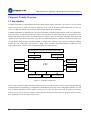
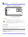
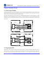
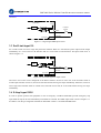
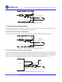
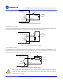
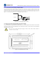
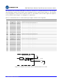
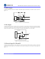
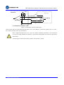
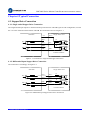
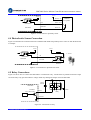
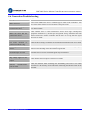
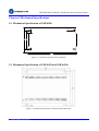
Hardware Installation Manual
SMC6480, SMC6490 and PMC6496
www.leadshine.com
HWMN-SMC6-R20120417
ii
Leadshine reserves the right to make changes without further notice to
any products herein to improve reliability, function or design. Leadshine
does not assume any liability arising out of the application or use of any
product or circuit described herein; neither does it convey any license
under its patent rights of others.
Leadshine’s general policy does not recommend the use of its products
in life support or aircraft applications wherein a failure or malfunction
of the product may directly threaten life or injury. According to
Leadshine’s terms and conditions of sales, the user of Leadshine’s
products in life support or aircraft applications assumes all risks of such
use and indemnifies Leadshine against all damages.
©2012 by Leadshine Technology, All Rights Reserved
Change Log
HWMN-SMC6-R20120417
Revision Date
Changes
Version
2011-4-17
Origin Create
HWMN-SMC6-R20120417
iii
Safety Items
!
Notice
Read this manual carefully before trying to install the motion controller
into your system. The person who setups the controller should have a
better understanding on electronics and mechanics. Contact Leadshine
technical guys when you have questions on this document.
!
Warning
Before running execute motion program, make sure the axes will not
impact anything. It is recommended to uncouple the motor from the load
before you are familiar with Leashine motion controller. Otherwise,
unexpected damage to the machine may occur.
!
Warning
Ensure that the power supply voltage dose not exceed the controller’s
input range. Double check the connections and make sure the power
lead polarity is correct.
HWMN-SMC6-R20120417
iv
Table of Contents
1. Family Overview......................................................................................................................................................... 1
1.1 Introduction ....................................................................................................................................................... 1
1.2 Product Covered ................................................................................................................................................ 2
1.3 Applications....................................................................................................................................................... 2
1.4 Order Information.............................................................................................................................................. 3
2. Controller Interface and Pin Assignment .................................................................................................................... 4
2.1 Controller Interface ........................................................................................................................................... 4
2.1.1. SMC6480 Interface ............................................................................................................................... 4
2.1.2. SMC6490 and PMC6496 Interface ....................................................................................................... 4
2.1.3. Wiring Notes.......................................................................................................................................... 5
2.2 Pin Assignment.................................................................................................................................................. 5
2.1.1. Power Connector ................................................................................................................................... 5
2.1.2. Control Signal Connector J21 ............................................................................................................... 6
2.1.3. I/O Connector J11.................................................................................................................................. 6
2.1.4. Expansion I/O Connector ...................................................................................................................... 7
2.1.5. Serial Port COM1.................................................................................................................................. 8
2.1.6. Serial Port COM2.................................................................................................................................. 9
2.1.7. Power-up level DIP Switch Function .................................................................................................... 9
2.1.8. E-Stop Connector (SMC6480) ............................................................................................................ 10
2.1.9. D/A Output Connector (SMC6480)..................................................................................................... 10
2.1.10. Encoder Connector(SMC6490 and PMC6496)................................................................................. 10
2.1.11. Manual Pulse Connector (SMC6490 and PMC6496)........................................................................ 11
2.3 Isolated and Non-isolated Power Output......................................................................................................... 12
2.4 USB Disk Interface ......................................................................................................................................... 12
Chapter 3 Interface Circuit ............................................................................................................................................ 13
3.1 Control Signal Output ..................................................................................................................................... 13
3.2 Origin Input ORG............................................................................................................................................ 13
3.3 End Limit input EL.......................................................................................................................................... 14
3.4 E-Stop Input EMG........................................................................................................................................... 14
3.5 General Purpose Digital Input......................................................................................................................... 15
3.5.1. Isolated General Purpose Digital Inputs.............................................................................................. 15
3.5.2. Non-isolated General Purpose Digital Inputs...................................................................................... 15
3.6 General Purpose Digital Output ...................................................................................................................... 16
3.6.1. Isolated General Purpose Digital Outputs ........................................................................................... 16
3.6.2. Non-isolated General Purpose Digital Outputs ................................................................................... 18
3.7 Expansion I/O Terminal Board ACC37-7480.................................................................................................. 18
3.8 PWM Output ................................................................................................................................................... 21
3.9 D/A Output ...................................................................................................................................................... 21
3.10 Encoder Input EA, EB and EZ ...................................................................................................................... 21
Chapter 4 Typical Connection ....................................................................................................................................... 23
HWMN-SMC6-R20120417
v
4.1 Stepper Drive Connection ............................................................................................................................... 23
4.1.1. Single-ended Stepper Drive Connection ............................................................................................. 23
4.1.2. Differential Input Stepper Drive Connection....................................................................................... 23
4.2 Servo Drive Connection .................................................................................................................................. 24
4.3 Proximity Sensor Connection.......................................................................................................................... 24
4.4 Photoelectric Sensor Connection..................................................................................................................... 25
4.5 Relay Connections........................................................................................................................................... 25
4.6 Connection Troubleshooting ........................................................................................................................... 26
Chapter 5 Mechanical Specifications ............................................................................................................................ 27
5.1 Mechanical Specification of SMC6480........................................................................................................... 27
5.1 Mechanical Specification of SMC6490 and SMC64596................................................................................. 27
Contact Us..................................................................................................................................................................... 28
HWMN-SMC6-R20120417
SMC6000 Series Motion Controller Hardware Installation Manual
Chapter 1 Family Overview
1.1 Introduction
Leadshine SMC6000 is 10/100M Ethernet-based general purpose motion controller. It provides 1 to 4 axes motion
control to stepper/servo motors for various operations. It can work in standalone mode without PC or work as a
slaver in an Ethernet network. The controller number in the network has no limitation.
Leadshine SMC6000 uses embedded microprocessor and FPGA to implement algorithm for multi-axes interpolation,
pulse generation, acceleration/deceleration control and processing of digital input/output in the hardware level,
offering high speed, high precision and stable features to motion control. It can output maximum 5MHz pulse and
supports up to 4-axes linear interpolation, any 2-axes circulation interpolation, continuous interpolation and S-curve
velocity profile. Programming of motion program is simple and it supports many language including Leadshine
BASIC, G-Code, Visual Basic and Visual C++. What’s more, Leadshine SMC6000 integrates isolated I/O, D/A
output, PWM output, encoder counter and manual input in one single package.
Control Signal Output and Isolated Digital Inputs/Ouputs
Encoder Interface
FPGA
D/A Output
PWM Output
CPU
Expansion I/O
MPG Interface
Ferroelectric
Memory
Isolated Power
USB Disk Interface
Serial Port
Ethernet Interface
Figure 1-1: Controller Architecture
The serial port COM1/COM2 and the RJ45 Ethernet port can be used for motion control or uploading/downloading
configuration data. Programming or configuration to SMC6000 requires only one PC with Ethernet interface or serial
port. Leadshine SMC6000 provides optional touch screen for easy operation in the field. Its built-in ferroelectric
memory can be used to store the dynamic motion parameter during execution of motion program. You can restore
these parameters in case of unexpected power-off.
HWMN-SMC6-R20120417
1
SMC6000 Series Motion Controller Hardware Installation Manual
1.2 Product Covered
This manual tries to specify the functionality, structure, connector pin assignment and connections of Leadshine
SMC6480, SMC6490 and PMC6496. Table 1-1 illustrates the key features of Leadhine SMC600.
Table 1-1 SMC6000 Motion Controller Specifications
SMC6480
SMC6490
PMC6496
Number of Controllable Axes
4
4
4
Pulse Output Frequency( MAX)
5.0MHz
5.0MHz
5.0MHz
Position Range
Interpolation Cycle
-2,147,483,647 to +2,147,483,648 (32 BIT)
300 us
General Purpose
300 us
24 inputs include 8 isolated inputs and 16 non-isolated inputs
Digital Inputs
General Purpose
32 inputs include 16 isolated inputs and 16 non-isolated inputs
Digital Outputs
D/A Outputs
2 Channels, 0.07~4.45V, 8 bit
Encoder Counter
-
-
-
4 Channels, Max 4 MHz bandwidth, 32 bit counter
Manual Pulse Input
PWM Output
300 us
1 Channel, Max 1MHz bandwidth
2 Channels, Max 1MHz bandwidth, duty-cycle 0~100%, 32-bit resolution
Flash Memory
32M Bytes
32M Bytes
8M Bytes
Ferroelectric Memory
-
32K Byte Optional
32K Bytes
Network Interface
10M/100M Ethernet
Serial Port
RS-232, 2 D-Shell 9-pin connector
USB Disk Interface
USB 1.1, 12Mbytes / s
External Power Supply
24VDC, 1100mA
Operating Temperature
0~50℃
0~50℃
0~50℃
Storage Temperature
-20~80℃
-20~80℃
-20~80℃
Size
208mm*116mm*42mm
Programming
186mm*147mm*42mm
G Code, BASIC, VB/VC library
1.3 Applications
•
•
•
•
•
•
•
•
Electronic assembly and measurement equipments
Semiconductor and LCD manufacturing & measurement equipments
Laser cutting/engraving/marking equipments
Vision & measurement automation equipments
Biotech sampling and handing devices
Robotics
Special CNC machines
Other automation system using stepper and servo
HWMN-SMC6-R20120417
2
SMC6000 Series Motion Controller Hardware Installation Manual
1.4 Order Information
Table 1-2 Order Information
Part Number
Description
SMC6480
Motion Controller SMC6480, BASIC
SMC6480G
Motion Controller SMC6480, G-Code
SMC6490-FM
Motion Controller SMC6490, BASIC, Ferroelectric Memory
SMC6490
Motion Controller SMC6490, BASIC
SMC6490-FM
Motion Controller SMC6490, G-Code, Ferroelectric Memory
SMC6490G
Motion Controller, SMC6490, G-Code
PMC6496
Motion Controller, PMC6496
Table 1-3 Accessories Information
Part Number
Description
CALBE37-DP-20
Cable for expansion I/O terminal board ACC37-7480, 37pin, 2000mm
ACC37-7480
Terminal board ACC37-7480 for expansion I/O, isolated amplifier
TK6070iH
Touch screen, 7 inch screen
HWMN-SMC6-R20120417
3
SMC6000 Series Motion Controller Hardware Installation Manual
Chapter 2 Controller Interface and Pin Assignment
2.1 Controller Interface
2.1.1. SMC6480 Interface
EGND
EGND
EGND
ORGU
ORGZ
ORGY
ORGX
ELUELU+
ELZELZ+
ELYELY+
ELXELX+
+5V
DIR4DIR4+
PUL4PUL4+
DIR3DIR3+
PUL3PUL3+
DIR2DIR2+
PUL2PUL2+
DIR1DIR1+
PUL1PUL1+
Leadshine SMC6480 has one control signal connector J21, one isolated I/O connector J11, one D/A output connector,
two serial port connector COM1&COM2, one non-isolated expansion I/O connector, one power-up level setting
switch for digital output 1-24, one RJ45 connector for Ethernet communication, one USB port for USB disk and one
power supply connector., as shown in figure 2-1.
RUN/LED1
LED2
COM1
POWER
EXGND
J11
E-Stop
32
IN1
IN2
IN3
IN4
IN5
IN6
IN7
IN8
IN9
IN10
IN11
IN12
IN13
IN14
IN15
IN16
OUT1
OUT2
OUT3
OUT4
OUT5
OUT6
OUT7
OUT8
PWM1
PWM2
VDD
EGND
EGND
EGND
EGND
EGND
1
EMG
Expansion IO
+
COM2
Power
-
USB Disk
Ethernet
D/A Output
J21
24V
Power-up Level Switch
1
32
Figure 2-1: SMC6480 Interface
2.1.2. SMC6490 and PMC6496 Interface
Leadshine SMC6490/PMC6496 has one control signal connector J21, one isolated I/O connector J11, two serial port
connector COM1&COM2, one manual pulse connector, one non-isolated expansion I/O connector, one encoder
connector, one power-up level setting switch for digital output 1-24, one RJ45 connector for Ethernet communication,
one USB port for USB disk and one power supply connector., as shown in figure 2-2.
HWMN-SMC6-R20120417
4
EGND
EGND
EGND
ORG4
ORG3
ORG2
ORG1
EL4EL4+
EL3EL3+
EL2EL2+
EL1EL1+
+5V
DIR4DIR4+
PUL4PUL4+
DIR3DIR3+
PUL3PUL3+
DIR2DIR2+
PUL2PUL2+
DIR1DIR1+
PUL1PUL1+
SMC6000 Series Motion Controller Hardware Installation Manual
1
Power-up Level Switch
LED2
Ethernet
S1
1
32
IN1
IN2
IN3
IN4
IN5
IN6
IN7
IN8
IN9
IN10
IN11
IN12
IN13
IN14
IN15
IN16
OUT1
OUT2
OUT3
OUT4
OUT5
OUT6
OUT7
OUT8
PWM1
PWM2
VDD
EGND
EGND
EGND
EGND
EMG
J11
MPG
RUN/LED1
COM1
POWER
+
Expansion I/O
-
COM2
Power
24V
USB Disk
Encoder Connector
J21 32
Figure 2-2: SMC6490/PMC6496 Interface
2.1.3. Wiring Notes
1) Make sure supply voltage is 24VDC and connecting polarity is correct.
!
2) Use normal RJ45 cable for network connections via Router or HUB. If it is direct connection to
PC, exchanges transmit and receive wire for one of the RJ45 connectors in the cable.
Caution
3) Please study the pin assignment and interface circuit of each connector in this manual carefully.
Make sure you understand them before trying to connect them.
2.2 Pin Assignment
2.1.1. Power Connector
The SMC6000 needs only one 24VDC regulated power supply for normal operation. Recommended power supply
current rating is 1100Amp. .
Table 2-1 Power Connector Pin Assignment (SMC6480, SMC6490 and PMC6496)
Power Connector Pin Assignment (SMC6480, SMC6490 and PMC6496)
Pin
Name
I/O
Description
1
24V +
I
Power Supply Input (Positive), 24VDC.
2
24V -
I
Power Ground (Negative)
HWMN-SMC6-R20120417
5
SMC6000 Series Motion Controller Hardware Installation Manual
2.1.2. Control Signal Connector J21
Control signal connector provides pulse and direction outputs for position and velocity control. End limit and origin
input are assigned in this connector. See table 2-2 for the detail.
Table 2-2 Control signal connector J21 pin assignment (SMC6480, SMC6490 and PMC6496)
Control Signal Connector Pin Assignment (SMC6480, SMC6490 and PMC6496)
Pin
Signal
I/O
Description
Pin
Signal
I/O
Description
1
PUL1+
O
Axis 1 Pulse +
17
+5V
O
+5V Power
2
PUL1-
O
Axis 1 Pulse -
18
ELx+
I
Axis 1 End Limit+, reference to EXGND
3
DIR1+
O
Axis 1 Direction +
19
ELx-
I
Axis 1 End Limit-, reference to EXGND
4
DIR1-
O
Axis 1 Direction -
20
Ely+
I
Axis 2 End Limit+, reference to EXGND
5
PUL2+
O
Axis 2 Pulse +
21
Ely-
I
Axis 2 End Limit-, reference to EXGND
6
PUL2-
O
Axis 2 Pulse -
22
ELz+
I
Axis 3 End Limit+, reference to EXGND
7
DIR2+
O
Axis 2 Direction +
23
ELz-
I
Axis 3 End Limit-, reference to EXGND
8
DIR2-
O
Axis 2 Direction -
24
Elu+
I
Axis 4 End Limit+, reference to EXGND
9
PUL3+
O
Axis 3 Pulse +
25
Elu-
I
Axis 4 End Limit-, reference to EXGND
10
PUL3-
O
Axis 3 Pulse -
26
ORGx
I
Axis 1 Origin Input
11
DIR3+
O
Axis 3 Direction +
27
ORGy
I
Axis 2 Origin Input
12
DIR3-
O
Axis 3 Direction -
28
ORGz
I
Axis 3 Origin Input
13
PUL4+
O
Axis 4 Pulse +
29
ORGu
I
Axis 4 Origin Input
14
PUL4-
O
Axis 4 Pulse -
30
EXGND
GND
Power Ground
15
DIR4+
O
Axis 3 Direction +
31
EXGND
GND
Power Ground
16
DIR4-
O
Axis 3 Direction -
32
EXGND
GND
Power Ground
2.1.3. I/O Connector J11
I/O connector J11 provides 16 isolated general purpose digital inputs and 8 isolated general purpose digital outputs.
All digital inputs in this connector can be configured as dedicated or special purpose inputs. See table 2-3 for more
detail.
Table 2-3 I/O Connector J11 pin assignment (SMC6480, SMC6490 and PMC6496)
I/O Connector J11 Pin Assignment(SMC6480, SMC6490 and PMC6496)
Pin
Name
I/O
Description
1
IN1
I*
Isolated General-purpose Digital input 1 / Run
2
IN2
I*
Isolated General-purpose Digital input 2 / Pause
3
IN3
I*
Isolated General-purpose Digital input 3 / Stop
4
IN4
I*
Isolated General-purpose Digital input 4 / Home
5
IN5
I*
Isolated General-purpose Digital input 5 / X++ (JOG Axis 1 in positive direction)
6
IN6
I*
Isolated General-purpose Digital input 6 / X-- (JOG Axis 1 in negative direction)
7
IN7
I*
Isolated General-purpose Digital input 7 / Y++((JOG Axis 2 in positive direction)
8
IN8
I*
Isolated General-purpose Digital input 8 / Y-- (JOG Axis 2 in negative direction)
HWMN-SMC6-R20120417
6
SMC6000 Series Motion Controller Hardware Installation Manual
9
IN9
I*
Isolated General-purpose Digital input 9 / Z++(JOG Axis3 in positive direction)
10
IN10
I*
Isolated General-purpose Digital input 10 / Z--(JOG Axis 3 in negative direction)
11
IN11
I*
Isolated General-purpose Digital input 11 / U++(JOG Axis 4 in positive direction)
12
IN12
I*
Isolated General-purpose Digital input 12 / U--(JOG Axis 4 in negative direction)
13
IN13/INP1
I*
Isolated General-purpose Digital input 13 / Axis 1 In-position Signal Input
14
IN14/INP2
I*
Isolated General-purpose Digital input 14 / Axis 2 In-position Signal Input
15
IN15/INP3
I*
Isolated General-purpose Digital input 15 / Axis 3 In-position Signal Input
16
IN16/INP4
I*
Isolated General-purpose Digital input 16 / Axis 4 In-position Signal Input
17
OUT1
O
Isolated General-purpose Digital output 1
18
OUT2
O
Isolated General-purpose Digital output 2
19
OUT3
O
Isolated General-purpose Digital output 3
20
OUT4
O
Isolated General-purpose Digital output 4
21
OUT5
O
Isolated General-purpose Digital output 5
22
OUT6
O
Isolated General-purpose Digital output 6
23
OUT7
O
Isolated General-purpose Digital output 7
24
OUT8
O
Isolated General-purpose Digital output 8
25
PWM1
O
Isolated PWM output 1
26
PWM2
O
Isolated PWM output 2
27
VDD
O
5V Power Output
28
EXGND
GND
External Power Ground
29
EXGND
GND
External Power Ground
30
EXGND
GND
External Power Ground
31
EXGND
GND
External Power Ground
32
EXGND
GND
External Power Ground (SMC6480)
32
EMG
I
Emergency Stop (SMC6490, PMC6496)
*Note: These inputs with asterisk (I*) can be configured as special purpose input.
2.1.4. Expansion I/O Connector
Expansion I/O provides you with additional 16 non-isolated general purse digital inputs and 16 non-isolated general
purpose digital outputs. Some digital inputs in this connector can be configured as dedicated or special purpose
inputs. See table 2-4 for more detail.
Table 2-4 Expansion I/O Connector Pin Assignment (SMC6480, SMC6490 and PMC6496)
Expansion I/O Connector Pin Assignment (SMC6480, SMC6490 and PMC6496)
Pin
Name
I/O
Description
1
IN17
I
Non-isolated General-purpose Digital input 17
2
IN18
I
Non-isolated General-purpose Digital input 18
3
IN19
I
Non-isolated General-purpose Digital input 19
4
IN20
I
Non-isolated General-purpose Digital input 20
HWMN-SMC6-R20120417
7
SMC6000 Series Motion Controller Hardware Installation Manual
5
IN21/ALM1
I*
Non-isolated General-purpose Digital input 21 / Axis 1 Alarm Signal Input
6
IN22/ALM2
I*
Non-isolated General-purpose Digital input 22 / Axis 2 Alarm Signal Input
7
IN23/ALM3
I*
Non-isolated General-purpose Digital input 23 / Axis 3 Alarm Signal Input
8
IN24/ALM4
I*
Non-isolated General-purpose Digital input 24 / Axis 4 Alarm Signal Input
9
IN25
I*
Non-isolated General-purpose Digital input 25 / Active Level configured by bit0 of S1
10
IN26
I*
Non-isolated General-purpose Digital input 26 / Active Level configured by bit0 of S1
11
IN27
I*
Non-isolated General-purpose Digital input 27 / Active Level configured by bit0 of S1
12
IN28
I*
Non-isolated General-purpose Digital input 28 / Active Level configured by bit0 of S1
13
IN29
I*
Non-isolated General-purpose Digital input 29 / Active Level configured by bit1 of S1
14
IN30
I*
Non-isolated General-purpose Digital input 30 / Active Level configured by bit1 of S1
15
IN31
I*
Non-isolated General-purpose Digital input 31 / Active Level configured by bit1 of S1
16
IN32
I*
Non-isolated General-purpose Digital input 32 / Active Level configured by bit1 of S1
17
VCC3.3
O
3.3V Power Output
18
VCC3.3
O
3.3V Power Output
19
GND
GND
5V/3.3V Power Ground
20
GND
GND
5V/3.3V Power Ground
21
OUT9
GND
Non-isolated General-purpose Output 9
22
OUT10
O
Non-isolated General-purpose Output 10
23
OUT11
O
Non-isolated General-purpose Output 11
24
OUT12
O
Non-isolated General-purpose Output 12
25
OUT13
O
Non-isolated General-purpose Output 13
26
OUT14
O
Non-isolated General-purpose Output 14
27
OUT15
O
Non-isolated General-purpose Output 15
28
OUT16
O
Non-isolated General-purpose Output 16
29
OUT17
O
Non-isolated General-purpose Output 17
30
OUT18
O
Non-isolated General-purpose Output 18
31
OUT19
O
Non-isolated General-purpose Output 19
32
OUT20
O
Non-isolated General-purpose Output 20
33
OUT21
O
Non-isolated General-purpose Output 21
34
OUT22
O
Non-isolated General-purpose Output 22
35
OUT23
O
Non-isolated General-purpose Output 23
36
OUT24
O
Non-isolated General-purpose Output 24
37
GND
GND
5V/3.3V Power Ground
*Note: These inputs with asterisk (I*) can be configured as special purpose inputs.
2.1.5. Serial Port COM1
COM1 is a D shell 9 pin male connector which has the transmitting and the receive pin for RS232 communication.
This port is used for configuration and uploading/downloading motion program. See table 2-5 for the detail.
HWMN-SMC6-R20120417
8
SMC6000 Series Motion Controller Hardware Installation Manual
Table 2-5 Serial port COM1 pin assignment (SMC6480, SMC6490 and PMC6496)
Serial Port COM1 Pin Assignment (SMC6480, SMC6490 and PMC6496)
Pin
Name
I/O
Description
1
NC
N/A
Not connected
2
RXD0
I
RS232 receive
3
TXD0
O
RS232 transmit
4
NC
N/A
Not connected
5
EXGND
GND
External power ground
6
NC
N/A
Not connected
7
NC
N/A
Not connected
8
NC
N/A
Not connected
9
NC
N/A
Not connected
2.1.6. Serial Port COM2
COM2 is a D shell 9 pin female connector which has the transmitting and the receive pin for RS232 communication.
This port is used for controller configuration or downloading/downloading motion program. See table 2-6 for the
detail.
Table 2-6 Serial port COM2 Pin assignment (SMC6480, SMC6490 and PMC6496)
Serial Port COM2 Pin Assignment (SMC6480, SMC6490 and PMC6496)
Pin
Name
I/O
Description
1
NC
N/A
Not connected
2
RXD0
I
RS232 receive
3
TXD0
O
RS232 transmit
4
NC
N/A
Not connected
5
EXGND
GND
External power ground
6
NC
N/A
Not connected
7
NC
N/A
Not connected
8
NC
N/A
Not connected
9
NC
N/A
Not connected
2.1.7. Power-up level DIP Switch Function
There is a 4 bit DIP switch for setting of power-up level for digital outputs 1-24. See table 2-7 for the detail.
HWMN-SMC6-R20120417
9
SMC6000 Series Motion Controller Hardware Installation Manual
Table 2-7 DIP Switch Function (SMC6480, SMC6490 and PMC6496)
Power-up Level DIP Switch Function (SMC6480, SMC6490 and PMC6496)
SWITCH
ON/OFF
Description
ON
Power-up level of digital outputs 17-24 is 0
OFF
Power-up level of digital outputs 17-24 is 1
ON
Power-up level of digital outputs 9-16 is 0
OFF
Power-up level of digital outputs 9-16 is 1
ON
Power-up level of digital outputs 5-8 is 0
OFF
Power-up level of digital outputs 5-8 is 1
ON
Power-up level of digital outputs 1-4 is 0
OFF
Power-up level of digital outputs 1-4 is 1
1
2
3
4
2.1.8. E-Stop Connector (SMC6480)
When the E-Stop input is activated, all the axes will stop and no pulse output. See table 2-8 for the pin assignment.
Figure 3-5 illustrates how to connect an E-step switch to the controller.
Table 2-8 E-Stop Connector Pin Assignment (SMC6480)
E-Stop Connector Pin Assignment (SMC6480)
Pin
Name
I/O
Description
1
EMG
I
E-stop Input
2
EXGND
GND
External power ground.
2.1.9. D/A Output Connector (SMC6480)
The D/A output is reference to AGND. Its swing rang is from 0.07-4.45V. The output circuit is shown in figure 3-18.
See the pin assignment in table 2-9.
Table2-9 D/A Output Connector Pin Assignment (SMC6480)
D/A Output Connector Pin Assignment
Pin
Name
I/O
Description
1
Analog A
O
D/A output channel A
2
Analog B
O
D/A output channel B
3
AGND
GND
D/A output ground
4
AGND
GND
D/A output ground
2.1.10. Encoder Connector(SMC6490 and PMC6496)
The encoder input can be used for pulse counting of position feedback. There are up to 4 channel AB phase and Z
index inputs with latched signal for capture of position. All of the inputs are TTL compatible
HWMN-SMC6-R20120417
10
SMC6000 Series Motion Controller Hardware Installation Manual
Table2-10 Encoder Connector Pin Assignment (SMC6490 and PMC6496)
Encoder Connector Pin Assignment (SMC6490 and PMC6496)
Pin
Name
I/O
Description
Pin
Name
I/O
1
5V
O
2
GND
GND
3
EA1+
4
Description
+5V Power Output
20
GND
GND
5V Power Ground
21
EA2+
I
Axis 2 Encoder Phase A +
I
Axis 1 Encoder Phase A +
22
EA2-
I
Axis 2 Encoder Phase A -
EA1-
I
Axis 1 Encoder Phase A -
23
EB2+
I
Axis 2 Encoder Phase B +
5
EB1+
I
Axis 1 Encoder Phase B +
24
EB2-
I
Axis 2 Encoder Phase B -
6
EB1-
I
Axis 1Encoder Phase B -
25
EZ2+
I
Axis 2 Encoder Index Z +
7
EZ1+
I
Axis 1 Encoder Index Z +
26
EZ2-
I
Axis 2 Encoder Index Z -
8
EZ1-
I
Axis 1 Encoder Index Z -
27
LTC2+
I
Axis 2 Latch Signal Input +
9
LTC1-
I
Axis 1 Latch Signal Input +
28
LTC2-
I
Axis 2 Latch Signal Input -
10
5V
O
+5V Power Output
29
GND
GND
11
GND
GND
5V Power Ground
30
EA4+
I
Axis 4 Encoder Phase A +
12
EA3+
I
Axis 3 Encoder Phase A +
31
EA4-
I
Axis 4 Encoder Phase A -
13
EA3-
I
Axis 3 Encoder Phase A -
32
EB4+
I
Axis 4 Encoder Phase B +
14
EB3+
I
Axis 3 Encoder Phase B +
33
EB4-
I
Axis 4 Encoder Phase B -
15
EB3-
I
Axis 3 Encoder Phase B -
34
LTC1+
I
Axis 1 Latch Signal Input +
16
EZ3+
I
Axis 3 Encoder Index Z +
35
EZ4-
I
Axis 4 Encoder Index Z -
17
EZ3-
I
Axis 3 Encoder Index Z -
36
NC
N/A
Not Connected
18
EZ4+
I
Axis 4 Encoder Index Z +
37
NC
N/A
Not Connected
19
5V
O
+5V Power Output
5V Power Ground
5V Power Ground
2.1.11. Manual Pulse Connector (SMC6490 and PMC6496)
Manual pulse from the MPG can be used to joy the axes during processing. Leadshine SMC6400B accepts AB phase
input signals. That is, A phase is lead or lag B phase by 90 degree and it represents the move direction. The pulse
frequency can be multiplied by 10 times or 100 times. You need to select which axis to be operated by pulling the
SEL pin to ground before sending the pulse. See table 2-11 for the pin assignments.
Do not connect the GND to EXGND See chapter 2.3 for more information.
!
Caution
Table 2-11 Manual Pulse Connector Pin Assignment (SMC6490 and PMC6496)
Manual Pulse Input Connector Pin Assignment (SMC6490 and PMC6496)
Pin
Name
I/O
1
PA
I
2
PB
I
Description
Pin
Name
I/O
Manual pulse input phase A
9
GND
GND
Internal 5V Power Ground
Manual pulse input phase B
10
GND
GND
Internal 5V Power Ground
HWMN-SMC6-R20120417
Description
11
SMC6000 Series Motion Controller Hardware Installation Manual
3
X10
I
10× Pulse Frequency, active Low.
11
SELy
I
Select Axis Y, active low.
4
X100
I
100× Pulse Frequency, active low.
12
SELz
I
Select Axis Z, active low.
5
SELx
I
Select Axis X, active low.
13
SELu
I
Select Axis U, active low.
6
GND
GND
Internal 5V Power Ground
14
+5V
O
Internal +5V power output f
7
GND
GND
Internal 5V Power Ground
15
+5V
O
Internal +5V power output
8
GND
GND
Internal 5V Power Ground
Note: The Manual Pulse Input of SMC6490/PMC6496 is non-isolated but the inside circuit is powered by internal
isolated power supply..
2.3 Isolated and Non-isolated Power Output
There are many power supply voltages output from SMC6000 controller. Figure 2-3 illustrate the relationship
between them.
+24V
EXGND
Power
Filter
24V to 5V
Converter
VDD (5V)
EXGND
+5V
Isolated 24V to
5V Converter
5V to 3V
Converter
+3.3V
GND
AGND
Figure 2-3: SMC6000 isolated and non-isolated power output
In figure 2-3, the 24V external power is converted into VDD (5V) directly. The +5V and +3.3V are completely
isolated from the external power to ensure the internal circuit work independently. The AGND is reference of the
D/A output and the +3.3V is used in the expansion I/O outputs. The VDD (5V) can be used for peripheral equipment
and its return ground is common with EXGND.
!
Note: 1) Never connect AGND or GND to EXGND. Otherwise the electronic interference will
coupled into the internal circuit.
Caution
2) Instead of 24V, the VDD output is 5V which is different from the other Leadshine controllers.
2.4 USB Disk Interface
Leadshine SMC6000 uses USB1.1 standard for the USB disk and can support any 2G or 4G USB disk in the market.
MAX transmission speed is 12Mb/s.
HWMN-SMC6-R20120417
12
SMC6000 Series Motion Controller Hardware Installation Manual
Chapter 3 Interface Circuit
3.1 Control Signal Output
Leadshine SMC6000 can control 4 axes stepper/servo motor at the same time. By default, the control signal PUL and
DIR of each axis represents pulse and direction signal. They can be configured as CW/CCW signal in the demo
software. See more information in SMC6000’s software manual.
The control signal output circuit and its connection to a differential input stepper drive is shown in figure 3-1. If the
stepper drive is single-ended input, connect it as figure 3-2. Negative output and +5V are used in the single-ended
connections. Please note that the PUL and DIR can only sink/source maximal 20mA which should be enough for the
opto-coupler.
Stepper Drive
SMC6000
PUL
ASIC
PUL+
PUL+
PUL-
PUL-
DIR+
DIR+
DIR-
DIR-
R
R
DIR
Figure 3-1: Differential Output of Control Signal PUL and DIR
Stepper Drive
SMC6000
+5V
PUL
PUL+
PUL-
ASIC
DIR
OPTO
PUL
R
DIR
R
DIR+
DIR-
Figure 3-2: Single-ended Output of Control Signal PUL and DIR
3.2 Origin Input ORG
ORG signal is used to detect the mechanical home/origin position in a machine. SMC6000’s ORG input circuit is
shown in figure 3-3. The built-in opto-coupler and low-pass filter prevent electronic interference from coupling into
the motion controller thus increase system reliability. See table 2-2 for pin assignment of ORG signal in the
HWMN-SMC6-R20120417
13
SMC6000 Series Motion Controller Hardware Installation Manual
connector.
SMC6000
24V+
Filter
ORGx
Original
Switch
(ORGy、z、u)
EXGND
EXGND
Figure 3-3: Origin Signal ORG Input Circuit
3.3 End Limit input EL
EL is used to limit axis move range and protect the machine. When it is activated, the pulse output will be output
immediately. EL+ can be used in CW direction and EL- can be used in CCW direction. The input circuit of EL is
shown in figure 3-4.
SMC6000
24V+
Filter
EL+ (EL-)
End Limit
EXGND
EXGND
Figure 3-4: End Limit Signal EL Input Circuit
The active level of EL can be configured in the Demo software. Set EL be active low if the end limit switch is
normal open and when it turns on, EL will be activated and the moving axis stops immediately. Otherwise, set EL be
active high if the end limit switch is normal close, and when it turns off, EL is activated and the moving axis stops
immediately.
3.4 E-Stop Input EMG
In order to protect operator and equipment in case of emergency, Leadshine SMC6000 provides emergency stop
input EMG to stop the all axes immediately when EMG is activated. The EMG input circuit is shown in figure 3-5.
See table 2-8 for the pin assignment of EMG for SMC6480 or table 2-3 for SMC6490/PMC6496.
HWMN-SMC6-R20120417
14
SMC6000 Series Motion Controller Hardware Installation Manual
SMC6400
24V+
Filter
E-stop Switch
EMG
EXGND
EXGND
Figure 3-5: Emergency Stop Signal EMG Input Circuit
3.5 General Purpose Digital Input
Leadhine SMC6000 motion controller has 16 isolated and 16 non-isolated general purpose digital inputs which can
be connected to switch, sensor or output signals form other controller.
3.5.1. Isolated General Purpose Digital Inputs
The input circuit is shown in figure 3-6. See table 2-3 for pin assignment of isolated general purpose inputs.
SMC6000
24V+
General Purpose
Digital Input
Filter
IN1 (IN2~IN16)
EXGND
EXGND
Figure 3-6: Isolated General Purpose Digital Input Circuit
3.5.2. Non-isolated General Purpose Digital Inputs
The non-isolated general purpose digital inputs are assigned in the expansion I/O connector and it is required to add
isolated device for those inputs when connected to peripheral equipment. Leadshine also provides optional terminal
board ACC37-7480 to user. Electronic noise will couple into the internal circuit and the controller will not function
ok when there is no isolation applied to these inputs. Figure 3-7 illustrates the non-isolated input circuit.
24V+
VCC3.3V
SMC6000
IN17
(IN18~32)
GND
4.7K
100
4.7K
Switch
0.1uF
EXGND
Figure 3-7: Non-isolated General Purpose Digital Input Circuit
HWMN-SMC6-R20120417
15
SMC6000 Series Motion Controller Hardware Installation Manual
3.6 General Purpose Digital Output
Leadshine SMC6000 provides 8 isolated and 16 non-isolated general purpose digital outputs.
3.6.1. Isolated General Purpose Digital Outputs
The isolated general purpose outputs adopt OC (open collector) output circuit. Digital output OUT1 and OUT2 use
MOSFET and they can withstand up to 1A current for relay. See figure 3-8 for interface circuit of OUT1 and OUT2.
Digital output OUT3~OUT8 adopts ULN2803 and the output current is limit to 60mA. See figure 3-9 for interface
circuit of digital output OUT3-OUT8. The pin assignments of isolated digital outputs are shown in table 2-3.
SMC6000
OUT1(OUT2)
OptoCoupler
EXGND
Figure 3-8: 1Amp isolated General Purpose Digital Output OUT1 and OUT2
SMC6000
OUT3 (OUT4~8)
OptoCoupler
EXGND
ULN2803
Figure 3-9: 60mA isolated General Purpose Digital Output OUT3-OUT8
Typical connections of general purpose digital outputs to different components are shown as follows:
1) Connections to LED
When connected the digital output to a LED, series a resistor between the power input and the LED to limit the
current to approx 10mA. The resistance is depending on the external power voltage. For example, 2K series resistor
is suitable for 24VDC power input. See figure 3-10 for how to connect the LED and series resistor.
HWMN-SMC6-R20120417
16
SMC6000 Series Motion Controller Hardware Installation Manual
SMC6000
Max 40V 60mA
R
OUT
External
Power Supply
24 VDC
EXGND
ULN2803
Figure 3-10: Connect Digital Output to LED
2) Connections to a Lamp
Use a warm-up resistor R for the connected lamp in order to increase lamp’s life-time. Determine the resistor by the
following rule: when the digital output is high level, this resistor should not turn on the lamp.
SMC6000
Max 40V 60mA
External
Power Suppy
OUT
24 VDC
R
EXGND
ULN2803
Figure 3-11: Connect Digital Output to Lamp
2) Connections to a Relay
The mechanical relay is inductance type load. If a mechanical relay is used, a diode must be paralleled to it to by
pass the inductance voltage generated when it is switched off. See figure 3-12 for the connections. The series resistor
is used to limit current to 60mA, in order to protect the output circuit of SMC6000.
SMC6000
Max 40V 60mA
OUT
R
Relay
External
Power Suppy
24 VDC
EXGND
ULN2803
Figure 3-12: Connect Digital Output to Relay
!
Caution
Note: 1) A diode must be paralleled to the relay to by pass inductive voltage. Connect a series resistor
between the digital output and the relay if the drive current is great than 60mA. Otherwise the digital
output will be risk of damage.
HWMN-SMC6-R20120417
17
SMC6000 Series Motion Controller Hardware Installation Manual
3.6.2. Non-isolated General Purpose Digital Outputs
Non-isolated general purpose digital outputs are assigned in the expansion I/O connector. Additional isolated circuit
should be used when connect them to peripheral equipment. You can also use Leadshine terminal board ACC37-7480
which offers isolation and anti-interference capacity. Typical connection of non-isolated digital output is shown in
figure 3-13. See the pin assignment of non-isolated digital outputs in table 2-4.
VCC3.3V
330
OUTPUT
SMC6000
OUT9
(OUT10~24)
Figure 3-13: Connect Digital Output to Relay
3.7 Expansion I/O Terminal Board ACC37-7480
For your convenience Leadshine provides terminal board ACC37-7480 for expansion I/O connections. This terminal
board offers isolation and current amplification to the expansion I/O. Figure 3-14 gives the pin out and mechanical
specification of ACC37-7480.
!
Caution
Note: The ACC37-7480 requires power supply to make it work. Please connect 24VDC to
connector J1 of ACC37-7480.
Figure 3-14: Terminal Board ACC37-7480
HWMN-SMC6-R20120417
18
SMC6000 Series Motion Controller Hardware Installation Manual
The expansion I/O of Leadshine SMC6000 is connected to connector X1 of terminal board ACC37-7480 through a
cable with DB37 connector. The connector J2 pin assignment of ACC37-7480 is shown in table 3-1. The connector
J3 pin assignment of ACC37-7480 is shown in table 3-2. The interface circuit of those inputs and outputs in
ACC37-7480 are shown in figure 3-15 and figure 3-16, respectively.
Table 3-1 Terminal Board ACC37-7480 General Purpose Input Connector J2 Pin Assignment
Terminal Board ACC37-7480 Connector J2 Pin Assignment
Pin
Name
I/O
Description
1
IN1
I
Expansion General-purpose Digital Input 17
2
IN2
I
Expansion General -purpose Digital input 18
3
IN3
I
Expansion General-purpose Digital Input 19
4
IN4
I
Expansion General-purpose Digital Input 20
5
IN5
I
Expansion General-purpose Digital Input 21
6
IN6
I
Expansion General-purpose Digital Input 22
7
IN7
I
Expansion General-purpose Digital Input 23
8
IN8
I
Expansion General-purpose Digital Input 24
9
IN9
I
Expansion General-purpose Digital Input 25
10
IN10
I
Expansion General-purpose Digital Input 26
11
IN11
I
Expansion General-purpose Digital Input 27
12
IN12
I
Expansion General-purpose Digital Input 28
13
IN13
I
Expansion General-purpose Digital Input 29
14
IN14
I
Expansion General-purpose Digital Input 30
15
IN15
I
Expansion General-purpose Digital Input 31
16
IN16
I
Expansion General-purpose Digital Input 32
17
EGND
GND
External Power Ground
18
EGND
GND
External Power Ground
Expansion I/O Terminal
Board ACC37-7480
24V+
Filter
Switch
IN1(IN2~16)
EGND
Figure 3-15: Interface circuit of IN1~IN16 in terminal board ACC37-7480
HWMN-SMC6-R20120417
19
SMC6000 Series Motion Controller Hardware Installation Manual
Expansion I/O Terminal
Board ACC37-7480
OUT1(OUT2~16)
60mA@40V
Filter
EGND
ULN2803
Figure 3-16: Interface circuit of OUT9-OUT24 in terminal board ACC37-7480
Table 3-2 Terminal Board ACC37-7480 General Purpose Outputs Connector J2 Pin Assignment
Pin Assignment of Connector J3 in Terminal Board ACC37-7480
1
OUT1
O
Expansion General-purpose Digital Output 9
2
OUT2
O
Expansion General-purpose Digital Output 10
3
OUT3
O
Expansion General-purpose Digital Output 11
4
OUT4
O
Expansion General-purpose Digital Output 12
5
OUT5
O
Expansion General-purpose Digital Output 13
6
OUT6
O
Expansion General-purpose Digital Output 14
7
OUT7
O
Expansion General-purpose Digital Output 15
8
OUT8
O
Expansion General-purpose Digital Output 16
9
OUT9
O
Expansion General-purpose Digital Output 17
10
OUT10
O
Expansion General-purpose Digital Output 18
11
OUT11
O
Expansion General-purpose Digital Output 19
12
OUT12
GND
Expansion General-purpose Digital Output 20
13
OUT13
GND
Expansion General-purpose Digital Output 21
14
OUT14
GND
Expansion General-purpose Digital Output 22
15
OUT15
GND
Expansion General-purpose Digital Output 23
16
OUT16
GND
Expansion General-purpose Digital Output 24
17
EGND
GND
External Power Ground
18
EGND
GND
External Power Ground
HWMN-SMC6-R20120417
20
SMC6000 Series Motion Controller Hardware Installation Manual
3.8 PWM Output
Leadshine SMC6000 provides two channels, 32bit PWM outputs with isolation. Its interface circuit is shown in
figure 3-17.
SMC6000
VDD5V
High Speed
Opto-coupler
PWM1 (PWM2)
ASIC
EXGND
EXGND
Figure 3-17: Interface circuit of PWM output
3.9 D/A Output
Leadshine SMC6480 provides 2 channel 8 bit D/A output with a voltage follower. Because the operational amplifier
is powered by a single 5VDC, the D/A output is between 0.07V and 4.45V. Figure 3-18 is the interface circuit of D/A
output. If 0V output is required, contact Leadshine to modify the SMC6480 for 0~2.5V D/A output.
SMC6480
+5V
+
DA1(DA2)
ASIC
Rf
R
AGND
AGND
Figure 3-18: Interface circuit of D/A output
3.10 Encoder Input EA, EB and EZ
Leadshine SMC6490/PMC6496 accepts differential encoder input which includes channel A signal EA, channel B
signal EB and Z index signal EZ. EA and EB are used for pulses counting. EZ can be taken as index signal. See
figure 3-17.
HWMN-SMC6-R20120417
21
SMC6000 Series Motion Controller Hardware Installation Manual
+5V
SMC6490
+5V
-
EA- (EB-,EZ-)
+
EA+ (EB+,EZ+)
Encoder
EA (EB,EZ)
26LS32
0V
GND
Figure 3-18: Interface circuit of encoder input
If the encoder output is single-ended like PNP, NPN or OC( open collector), connect the signals to the EA+, EB+ ,
EZ+ and leave the EA-, EB-, EZ- unconnected.
!
Note: 1) High level input of EA+, EA-, EB+, EZ+ and EZ- should be greater than 3.5V and less than
5V. Low level input should be less than 0.5V. The encoder should offer 6mA current at the least for
each channel.
Caution
2) Don’t forget to connect the encoder ground to the controller’s ground.
HWMN-SMC6-R20120417
22
SMC6000 Series Motion Controller Hardware Installation Manual
Chapter 4 Typical Connection
4.1 Stepper Drive Connection
4.1.1. Single-ended Stepper Drive Connection
The singled-ended input requires a common-anode input for the PUL and DIR signal. In such configuration, connect
the +5V to the common terminal of PUL and DIR. The connection is shown in figure 4-1.
SMC6000
Stepper Motor Drive
+5V
OPTO
R
PUL+
PUL
PUL-
PUL
R
DIR+
DIR
DIR-
DIR
Leadshine DM422C
Figure 4-1: Connections to single-ended stepper motor drive
4.1.2. Differential Input Stepper Drive Connection
The connection is accordingly. See figure 4-2.
SMC6000
Stepper Motor Drive
PUL+
PUL+
PUL1-
PUL-
R
PUL
DIR+
R
DIR+
DIR
DIRDIRLeadshine DM556
Figure 4-2: Differential input stepper motor drive connections
HWMN-SMC6-R20120417
23
SMC6000 Series Motion Controller Hardware Installation Manual
4.2 Servo Drive Connection
The connections to Panasonic servo motor drive is shown in figure 4-3.
Panasonic Servo Drive
SMC6000
Twisted Pair
PUL1+
PULS1
PUL1-
PULS2
DIR1+
SIGN1
DIR1-
SIGN2
PUL
DIR
Twisted Pair
24V+
INP1
COIN+
COINCOM+
OUT3
Optoisolator
EXGND
SRV-ON
COM-
24V+
+24V
24V-
Ground
24V Power
Supply
Figure 4-3: Connections to Panasonic AC servo motor drive
Note: Contact Leadshine at [email protected] if you have any questions or problems on the connection.
4.3 Proximity Sensor Connection
Figure 4-4 illustrates the connection between Leadshine SMC6000 and proximity sensor. Here we take the OMRON
TL-Q5MC2 as example.
HWMN-SMC6-R20120417
24
SMC6000 Series Motion Controller Hardware Installation Manual
24 V+
24 V+
Brown +V
SMC6000
IN
Black OUT
EXGND
Blue 0V
OMRON
TL-Q5MC2
Figure 4-4: Connections to proximity sensor
4.4 Photoelectric Sensor Connection
Figure 4-4 illustrates the connection between Leadshine SMC6000 and proximity sensor. Here we take the RG150-8
as example.
24 V+
24 V+
i = 10 mA
IN
SMC6000
EXGND
RG150-8
Figure 4-5: Connections to photoelectric sensor
4.5 Relay Connections
Figure 4-6 shows how to connect the SMC6000 to a mechanical relay. A diode must be parallel between the input
coil of the relay to by pass the inductive voltage which may damage the output circuit of SMC6000.
Diode
1N4001
8
6
4
2
7
5
3
1
SMC6000
ULN2803
40V, 60mA Max
OUT3
24 VDC
Relay
Filter
EXGND
Figure 4-6: Connections to relay
HWMN-SMC6-R20120417
25
SMC6000 Series Motion Controller Hardware Installation Manual
4.6 Connection Troubleshooting
Symptom
Advise
Motor not move.
Please check whether the drive’s command type is match to the controller’s. You
can use the demo software to test and observe the pulse count.
Controller can output pulse
but motor not move
Check the connections between the drive and the motion controller. Make sure the
drive has not alarm.
Motor can move but not
position not correct
Check whether there is other interference source from large current/power
equipment. Eliminate it by twisted pair and ground wiring. Sometimes the limit
resistor between the motion controller and the drive is too big thus the signal
current is too small.
Motor can be controlled
but motor vibration or
position overshoot is big.
Check the drive settings or whether the acceleration/deceleration time is too small.
Home position
correct.
Check whether there is interference coupled into the encoder or origin signal.
Make sure the shielding of the cable had been grounded.
is
not
End limit input not work
End limit sensor not work. End limit signal may be interfered.
Big voltage ripple on DA
output
Check whether the DA output is reference to AGND.
Ethernet
communication
port not work
Check the Ethernet cable. Exchange the transmitting and receive wire when
connected to a PC directly. Power-off before connecting the Ethernet cable to the
controller.
HWMN-SMC6-R20120417
26
SMC6000 Series Motion Controller Hardware Installation Manual
Chapter 5 Mechanical Specifications
5.1 Mechanical Specification of SMC6480
4-R3
5
118 78
203.5
Figure 5-1: Mechanical Specification of SMC6480
5.1 Mechanical Specification of SMC6490 and SMC64596
Figure 5-2: Mechanical Specification of SMC6490 and PMC6496
HWMN-SMC6-R20120417
27
SMC6000 Series Motion Controller Hardware Installation Manual
Contact Us
China Headquarters
Address: 3/F, Block 2, Nanyou Tianan Industrial Park, Nanshan District Shenzhen, China
Web: http://www.leadshine.com
Sales Hot Line:
Tel: 86-755-2641-7674 (for Asia, Australia, Africa areas)
86-755-2640-9254 (for Europe areas)
86-755-2641-7617 (for America areas)
Fax: 86-755-2640-2718
Email: [email protected].
Technical Support:
Tel: 86-755-2641-8447, 86-755-2641-8774, 86-755-2641-0546
Fax: 86-755-2640-2718
Email: [email protected](for All)
Leadshine U.S.A
Address: 25 Mauchly, Suite 318 Irvine, California 92618
Tel: 1-949-608-7270
Fax: 1-949-608-7298
Web: http://www.leadshineUSA.com
Email: [email protected] and [email protected].
HWMN-SMC6-R20120417
28


![FV1100-LNX - FAST CORPORATION[株式会社ファースト]](http://vs1.manualzilla.com/store/data/006542967_2-61dcc976f15352cc05847a1f203ad7c3-150x150.png)