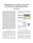
1
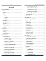
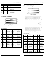
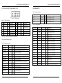
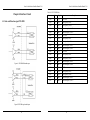
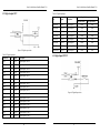
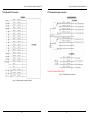
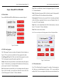
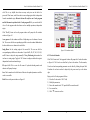
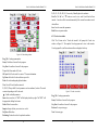
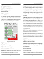
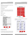
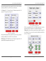
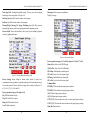
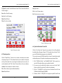
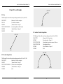
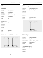
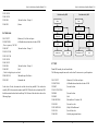
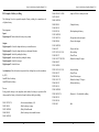
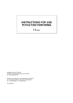
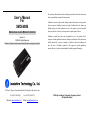
User’s Manual
For
SMC6400B
Stand-Alone 4-Axis Motion Controller
Version 1.0
©2009 All Rights Reserved
Attention: Please read this manual carefully before using the controller!
The content in this manual has been carefully prepared and is believed to be accurate,
but no responsibility is assumed for inaccuracies.
Leadshine reserves the right to make changes without further notice to any products
herein to improve reliability, function or design. Leadshine does not assume any
liability arising out of the application or use of any product or circuit described
herein; neither does it convey any license under its patent rights of others.
Leadshine’s general policy does not recommend the use of its products in life
support or aircraft applications wherein a failure or malfunction of the product may
directly threaten life or injury. According to Leadshine’s terms and conditions of
sales, the user of Leadshine’s products in life support or aircraft applications
assumes all risks of such use and indemnifies Leadshine against all damages.
3/F, Block 2, Nanyou Tianan Industrial Park, Nanshan Dist, Shenzhen, China
Tel: (86)755-26434369
Web site: www.leadshine.com
Fax: (86)755-26402718
E-Mail: [email protected]
©2009 by Leadshine Technology Company Limited.
All Rights Reserved
Stand –Alone Motion Controller Manual V1.0
Contents
Table of Contents
Chapter 1 General Information ..................................................................................... 1
1.1 Introduction ..................................................................................................... 1
1.2 Features ........................................................................................................... 1
1.3 Specification.................................................................................................... 3
1.3.1 Performance ......................................................................................... 3
1.3.2 I/O signals ............................................................................................ 3
1.3.3 User program memory.......................................................................... 3
1.4 Power Supply .................................................................................................. 3
1.5 Communication Interface ................................................................................ 3
1.6 Environment .................................................................................................... 3
1.7 Mechanical Specification ................................................................................ 4
1.8 Applications..................................................................................................... 4
Chapter 2 Installation .................................................................................................... 5
2.1 Package Connect ............................................................................................. 5
2.2 Unpacking ....................................................................................................... 5
2.3 Hardware Installation ...................................................................................... 6
Chapter 3 Connectors .................................................................................................... 6
3.1 Connectors on logic board............................................................................... 7
3.1.1 Connector XL1 - Reserved................................................................... 7
3.1.2 Connector XL2 – RS232 Serial port .................................................... 8
3.1.3 Connector XL3 - USB disk interface ................................................... 8
3.1.4 Connector XL4 - Reserved................................................................... 8
3.1.5 Connector XL5 - Manual pulse input interface .................................... 8
3.2 Connectors on drive board .............................................................................. 9
3.2.1 Connector XD1 – 24VDC power input .............................................. 10
3.2.2 Connector XD2 – Emergency stop input............................................ 10
3.2.3 Connector XD3 – Reserved................................................................ 10
3.2.4 Connector XD4 – Axis X control signal............................................. 10
3.2.5 Connector XD5 – Axis Y control signal............................................. 11
I
3.2.6 Connector XD6 – Axis Z control signal ............................................. 12
3.2.7 Connector XD7 – Axis U control signal............................................. 13
3.2.8 Connector XD8 – Axis X&Y Digital I/O ........................................... 14
3.2.9 Connector XD9 – Axis Z&U Digital I/O ........................................... 15
3.2.10 Connector XD10 – Digital Output 17 to 24 ..................................... 16
3.3 Special function input.................................................................................... 16
3.4 Dedicated I/O ................................................................................................ 17
Chapter 4 Interface Circuit .......................................................................................... 18
4.1 Pulse and Direction signal PUL/DIR ............................................................ 18
4.2 Digital output OUT ....................................................................................... 20
4.3 Digital input INPUT...................................................................................... 21
4.4 Origin signal ORG ........................................................................................ 22
4.5 Slow down signal SD .................................................................................... 23
4.6 In-position signal INP ................................................................................... 23
4.7 End limit signal EL+ & EL-.......................................................................... 24
4.8 Alarm Signal ALM ........................................................................................ 26
4.9 Emergency stop signal EMG......................................................................... 26
5.0 Manual pulse input PA & PB......................................................................... 27
Chapter 5 Connections ................................................................................................ 27
5.1 Connection to differential stepping driver..................................................... 27
5.2 Connection to single-ended stepping driver .................................................. 28
5.3 Connection to servo driver ............................................................................ 29
5.4 Dedicated I/O connection.............................................................................. 30
5.5 Manual pulse input connection...................................................................... 31
Chapter 6 Demo HMI for SMC6400B ........................................................................ 32
6.1 Root window ................................................................................................. 32
6.2 Edit G-code program..................................................................................... 32
6.2.1 File attribute window.......................................................................... 33
6.2.2 G-code edit window ........................................................................... 35
6.2.3 G-code view window.......................................................................... 37
6.2.4 Teaching and playback window ......................................................... 38
II
Stand –Alone Motion Controller Manual V1.0
Stand –Alone Motion Controller Manual V1.0
6.2.5 G-code help window .......................................................................... 40
6.3 Parameter and option settings........................................................................ 40
6.4 Run G-code program..................................................................................... 53
6.5 Manual operation........................................................................................... 54
6.6 Upload and download G-code file................................................................. 55
6.7 I/O Status....................................................................................................... 56
Chapter 7 G-codes Overview ...................................................................................... 58
7.1 Coordinates system ....................................................................................... 58
7.2 Absolute and relative coordinates.................................................................. 59
7.3 G-code function in SMC6400B..................................................................... 60
Chapter 8 G-code Example ......................................................................................... 62
8.1 Line ............................................................................................................... 62
8.2 Circular interpolation .................................................................................... 62
8.3 Another Circular interpolation....................................................................... 63
8.4 G92................................................................................................................ 64
8.4.1 Sub-program....................................................................................... 64
8.4.2 Relative move using absolute coordinates.......................................... 65
8.5 Jump and Repeat ........................................................................................... 65
8.6 Multi-task ...................................................................................................... 66
8.7 M89 ............................................................................................................... 67
8.8 Example of battery welding .......................................................................... 68
Chapter 1 General Information
1.1 Introduction
The SMC6400B motion controller is Leadshine’s high performance, stand-alone
motion controller, which based on a 32-bit RISC CPU. It offers 1 to 4 axes motion
control for stepping motors or servo motors to accomplish various operations The
SMC6400B supports standard ISO G-code programming. The user can edit G-code
program with HMI or in a PC before download the program to the controller through
RS232 serial port or USB disk.
The SMC6400B can generate pulse control signal (up to 9.8 MHz) to control servo
or stepping system. The pulse output type can either be PUR/DIR or CW/CCW. 28
general purpose digital inputs and 28 general purpose digital outputs are built inside
the SMC6400B. In multi-axis operation, the SMC6400B provides linear
interpolation by any 2, any 3, or even all-4 axes. And any 2 axes can perform
circular interpolation. It also supports trapezoidal/s-curve velocity profile and the
continuous interpolation function.
There are totally 41 instructions (14 G-codes and 17 M-codes) has been carefully
designed for user programming, offering motion control and program flow control
including jumping, looping and subprogram calls, with or without condition.
SMC6400B also support multi-task and variable declaration. Most of the
instructions are coincident with standard G-codes and easily understanding.
1.2 Features
u
u
u
u
u
Stand-alone Operation
Supports G-code programming
32-bit CPU, 60MHz, Rev1.0
Pulse output rate up to 9.8MHz
6 pulse/dir output modes: Pulse /DIR, CW/CCW etc.
III
Tel: +086 0755-26434369
1
Web Site: www.leadshine.com
Stand –Alone Motion Controller Manual V1.0
Stand –Alone Motion Controller Manual V1.0
1.3 Specification
1.3.1 Performance
u
u
u
u
u
Number of controllable axes: 4 axes.
Internal reference clock: 60 MHz
Pulse output frequency: 1 pps ~ 9.8 Mpps
Linear and circular interpolation accuracies: ±0.5 LSB
Maximum manual pulser input frequency: 100KHz
1.3.2 I/O signals
u
u
u
u
u
u
Number of general purpose digital input: 28 (Isolated)
Number of general purpose digital output: 28 (Isolated)
Command signals: PUL and DIR (Non-isolated)
Mechanical limit/switch signal input pins: ±EL, SD and ORG (Isolated)
Servo motor interface I/O pins: INP, ALM and ERC (Isolated)
Pulser signal input pin: PA and PB (Non-isolated)
1.3.3 User program memory
Figure 1-1 SMC6400B Control System
u
u
u
u
u
u
u
u
u
u
u
2~4 axes linear interpolation
2 axes circular interpolation
Multi-axis continuous interpolation
2 home return modes
Trapezoidal and S-curve velocity profiles programmable
Multi-axis, simultaneous start/stop
Position limit and return home signals for each axis
Standard servo motor control signal for each axis
28 general digital inputs with Opto-isolated
28 general digital outputs with Opto-isolated
HMI optional
2
u
User program:9999 lines G-code for each G-code program
1.4 Power Supply
u
24VDC±5%
1.5 Communication Interface
u
u
USB disk interface: USB1.1
Serial interface: RS-232
1.6 Environment
u
Operating temperature: 0℃~50℃
Tel: +086 0755-26434369
3
Web Site: www.leadshine.com
Stand –Alone Motion Controller Manual V1.0
Stand –Alone Motion Controller Manual V1.0
u
u
Storage temperature: -20℃~80℃
Humidity: 5%RH ~ 85%RH
Chapter 2 Installation
1.7 Mechanical Specification ( Unit = mm[inch])
This chapter describes how to install SMC6400B
2.1 Package Connect
Besides this User's Manual (Electronic Edition), the package also includes the
following items, depending to your actual order:
u SMC6400B (1 piece) - 4-Axis Stand-Alone Motion Controller
u Cable15-1.0 (4 piece) – Control signal cable for each axis
u ACC6400 (1 piece) - Terminal Board for digital I/O.
u Cable20-0.4 (2 piece) – Cable for CC6400.
u Cable10-0.4 (1 piece, Optional) – Cable for digital output 17-24
u Cable10-0.4 (1 piece, Optional) – Cable for manual pulse input
u Touch Screen (1 piece, Optional) – HMI and setting parameters
u CABLE09-1.0 (1 piece, Optional) – RS232 cable connected to HMI
u Leadshine All-in-one CD(Including the software)
If any of these items are missing or damaged, contact the dealer from whom you
purchased the product or Leadshine.
2.2 Unpacking
1.8 Applications
u
u
u
u
u
u
u
Electronic assembly and measurement equipments
Semiconductor and LCD manufacturing &measurement equipments
Laser cutting/engraving/marking equipments
Vision & measurement automation equipments
Biotech sampling and handing devices
Robotics
Special CNC machines
4
As with any electronic device, you should take care while handling to avoid damage
from static electricity. Before removing the SMC6400B from its packaging, ground
yourself to eliminate any stored static charge. The controller contains electro-static
sensitive components that can be easily damaged by static electricity. Therefore, the
controller should be handled on a grounded anti-static mat. Inspect the card module
carton for obvious damage. Shipping and handling may cause damage to your module.
Be sure there is no shipping and handling damage on the carton before continuing.
Note: Do not attempt to install a damaged controller.
5
Stand –Alone Motion Controller Manual V1.0
2.3 Hardware Installation
Stand –Alone Motion Controller Manual V1.0
3.1 Connectors on logic board
Before installation, the user needs to prepare a 24VDC power supply which offers
2.0Amp output current at the least.
Installation Procedures
1. Turn off the 24VDC power supply;
2. Before handling the controller, discharge any static buildup on your body by
touching the metal case of the computer.
3. Connect the two power leads to SMC6400B’s 24VDC power input connector.
4. Connect the terminal board and corresponding cables to SMC6400B, depending
on your configuration. See the following chapters for more information.
5. If you have ordered a HMI, connect it to the controller’s RS232 interface via
Calbe09-1.0. Otherwise, you need to prepare a computer with one serial port at
least. Connect the controller to computer’s serial port via Cable09-1.0.
Chapter 3 Connectors
SMC6400B consists of a logic board and a drive board, which are interconnected by
two connectors on the side of the boards. A couple of connectors are assembled on the
boards for different usage. See Figure 3-1 for more details.
Figure 3-2 Logic board layout
Table 3-1 Connectors on logic board
Logic Board
Connector
Drive Board
Figure 3-1 SMC6400B structure
Description
Connector
XL1
Reserved
XL4
Reserved
XL2
RS232 serial port
XL5
Manual pulse input interface
XL3
USB disk interface
3.1.1 Connector XL1 - Reserved
It is reserved for further development.
6
Description
7
Stand –Alone Motion Controller Manual V1.0
Stand –Alone Motion Controller Manual V1.0
3.1.2 Connector XL2 – RS232 Serial port
Table 3-3 XL5 pin function
This port is used for communication between SMC6400B and computer or HMI by a
serial cable.
Pin
Signal
I/O
Description
Pin
Signal
I/O
Description
1
NC
-
Not connected
6
*VCC
O
5VDC
2
NC
-
Not connected
7
*GND
-
Ground
3
NC
-
Not connected
8
*GND
-
Ground
4
NC
-
Not connected
9
PA
I
Phase A of Manual pulse
5
*VCC
O
5VDC
10
PB
I
Phase B of Manual pulse
Table 3-2 XL2 Pin function
Pin
Signal
I/O
Description
Pin
Signal
I/O
Description
1
NC
-
Not connected
6
NC
-
Not connected
2
RX
I
RS232 receive
7
NC
-
Not connected
3
TX
O
RS232 transmit
8
NC
-
Not connected
4
NC
-
Not connected
9
NC
-
Not connected
5
GND
GND
Ground
*Note: VCC is generated by internal circuit; do not connect GND to power ground EGND.
3.2 Connectors on drive board
Not connected
3.1.3 Connector XL3 - USB disk interface
If G-code programs are stored in a USB Disk, the user can load or reload them form it
via this port.
3.1.4 Connector XL4 - Reserved
It is reserved for further development.
3.1.5 Connector XL5 - Manual pulse input interface
Figure 3-4 Drive board layout
Figure 3-3 XL5 pin layout
8
9
Stand –Alone Motion Controller Manual V1.0
Stand –Alone Motion Controller Manual V1.0
Table 3-4 Connectors on drive board
Table 3-7 Pin function of XD4
Connector
Description
Connector
Description
Pin
Signal
I/O
Description
XD1
24VDC power input
XD6
Axis Z control signal
1
VCC
O
+5VDC Power
XD2
Emergency stop input
XD7
Axis U control signal
2
PUL1-
O
Pulse signal(-),Axis X
XD3
Reserved
XD8
Axis X&Y digital I/O
3
DIR1-
O
Direction signal(-), Axis X
XD4
Axis X control signal
XD9
Axis Z&U digital I/O
4
ERC1
O
Error clear signal, Axis X
XD5
Axis Y control signal
XD10
Digital output 17 to 24
5
INPUT17
I*
Digital input 17 or Manual pulse input function
6
ORG1
I
Origin signal, Axis X
7
EL1-
I
End limit signal(-), Axis X
3.2.1 Connector XD1 – 24VDC power input
Table 3-5 XD1 Pin function
8
EGND
GND
Power Ground
Pin
Signal
I/O
Description
Pin
Signal
I/O
Description
9
PUL1+
O
Pulse signal(+), Axis X
1
VDD
I
24VDC power
2
EGND
GND
Power Ground
10
DIR1+
O
Direction signal(+), Axis X
11
OUT25
O*
Digital output 25,
12
INP1 / INPUT19
I*
Axis X in position signal or Digital input 19
3.2.2 Connector XD2 – Emergency stop input
Table 3-6 XD3 pin function
13
ALM1
I
Alarm signal, Axis X
Pin
Signal
I/O
Description
Pin
Signal
I/O
Description
14
SD1/ INPUT18
I*
Axis X slow down signal or Digital input 18
1
EMG
I
Emergency stop
2
EGND
GND
Power Ground
15
EL1+
I
End limit signal, Axis X
3.2.3 Connector XD3 – Reserved
3.2.5 Connector XD5 – Axis Y control signal
It is reserved for further development.
3.2.4 Connector XD4 – Axis X control signal
Figure 3-6 XD5 pin layout
Table 3-8 XD5 pin function
Figure 3-5 XD4 Pin layout
10
Pin
Signal
I/O
Description
1
VCC
O
+5VDC Power
2
PUL2-
O
Pulse signal(-),Axis Y
11
Stand –Alone Motion Controller Manual V1.0
Stand –Alone Motion Controller Manual V1.0
3
DIR2-
O
Direction signal(-), Axis Y
7
EL3-
I
End limit signal(-), Axis Z
4
ERC2
O
Error clear signal, Axis Y
8
EGND
GND
Power Ground
5
INPUT20
I*
Digital input 20 or Manual pulse input function
9
PUL3+
O
Pulse signal(+), Axis Z
6
ORG2
I
Origin signal, Axis Y
10
DIR3+
O
Direction signal(+), Axis Z
7
EL2-
I
End limit signal(-), Axis Y
11
OUT27
O*
Digital output 27,
8
EGND
GND
Power Ground
12
INP3 / INPUT25
I*
In position signal, Axis Z or Digital input 25
9
PUL2+
O
Pulse signal(+), Axis Y
13
ALM3
I
Alarm signal, Axis Z
10
DIR2+
O
Direction signal(+), Axis Y
14
SD3 / INPUT24
I*
Axis Z slow down signal or Digital input 24
11
OUT26
O*
Digital output 25,
15
EL3+
I
End limit signal, Axis Z
12
INP2 / INPUT22
I*
Axis Y in position signal, or Digital input 22
13
ALM2
I
Alarm signal, Axis Y
14
SD2 / INPUT22
I*
Axis Y slow down signal or Digital input 22
15
EL2+
I
End limit signal, Axis Y
3.2.7 Connector XD7 – Axis U control signal
3.2.6 Connector XD6 – Axis Z control signal
Figure 3-8 XD7 pin layout
Table 3-10 XD7 pin function
Figure 3-7 XD6 pin layout
Table 3-9 XD6 pin function
Pin
Signal
I/O
Description
1
VCC
O
+5VDC Power
2
PUL4-
O
Pulse signal(-),Axis U
3
DIR4-
O
Direction signal(-), Axis U
Pin
Signal
I/O
Description
4
ERC4
O
Error clear signal, Axis U
1
VCC
O
+5VDC Power
5
INPUT26
I*
Digital input 26 or Manual pulse input function
2
PUL3-
O
Pulse signal(-),Axis Z
6
ORG4
I
Origin signal, Axis U
3
DIR3-
O
Direction signal(-), Axis Z
7
EL4-
I
End limit signal(-), Axis U
4
ERC3
O
Error clear signal, Axis Z
8
EGND
GND
Power Ground
5
INPUT23
I*
Digital input 23 or Manual pulse input function
9
PUL4+
O
Pulse signal(+), Axis U
6
ORG3
I
Origin signal, Axis Z
10
DIR4+
O
Direction signal(+), Axis U
12
13
Stand –Alone Motion Controller Manual V1.0
Stand –Alone Motion Controller Manual V1.0
3.2.9 Connector XD9 – Axis Z&U Digital I/O
11
OUT28
O*
Digital output 28,
12
INP4 / INPUT28
I*
In position signal, Axis U or Digital input 28
13
ALM4
I
Alarm signal, Axis U
14
SD4 / INPUT27
I*
Axis U slow down signal or Digital input 27
15
EL4+
I
End limit signal, Axis U
Figure 3-10 XD9 pin layout
3.2.8 Connector XD8 – Axis X&Y Digital I/O
Figure 3-9 XD8 pin layout
Table 3-11 XD8 pin function
Pin
Signal
I/O
Description
Pin
Signal
I/O
Description
1
E5V
O
*+5VDC power
11
OUT1
O
Digital output 1
2
EGND
GND
Ground
12
OUT2
O
Digital output 2
Table 3-12 XD8 pin function
3
INPUT8
I
Digital input 8
13
OUT3
O
Digital output 3
Pin
Signal
I/O
Description
Pin
Signal
I/O
Description
4
INPUT7
I
Digital input 7
14
OUT4
O
Digital output 4
1
E5V
O
*+5VDC power
11
OUT16
O
Digital output 16
5
INPUT6
I
Digital input 6
15
OUT5
O
Digital output 5
2
EGND
GND
Ground
12
OUT15
O
Digital output 15
6
INPUT5
I
Digital input 5
16
OUT6
O
Digital output 6
3
INPUT9
I
Digital input 9
13
OUT14
O
Digital output 14
7
INPUT4
I
Digital input 4
17
OUT7
O
Digital output 7
4
INPUT10
I
Digital input 10
14
OUT13
O
Digital output 13
8
INPUT3
I
Digital input 3
18
OUT8
O
Digital output 8
5
INPUP11
I
Digital input 11
15
OUT12
O
Digital output12
9
INPUT2
I
Digital input 2
19
COM
O
+24VDC power
6
INPUT12
I
Digital input 12
16
OUT11
O
Digital output 11
10
INPUT1
I
Digital input 1
20
EGND
GND
Ground
7
INPUT13
I
Digital input 13
17
OUT10
O
Digital output 10
8
INPUT14
I
Digital input 14
18
OUT9
O
Digital output 9
9
INPUT15
I
Digital input 15
19
COM
O
+24VDC power
10
INPUT16
I
Digital input 16
20
EGND
GND
Ground
*Note: The +5VDC power is generated by internal circuit.
Figure 3-11 Terminal board ACC6400 pin layout
*Note: The +5VDC power is generated by internal circuit.
14
15
Stand –Alone Motion Controller Manual V1.0
3.2.10 Connector XD10 – Digital Output 17 to 24
Stand –Alone Motion Controller Manual V1.0
3.4 Dedicated I/O
Table 3-16 Dedicated output
Connector
Pin
Description
OUT1
XD8
11
It can be set by M07 & M08
OUT2
XD8
12
It can be set by M09 & M10
OUT3
XD8
13
It can be set by M11 & M12
Digital Output
Figure 3-12 XD10 pin layout
Table 3-13 XD10 pin function
Pin
Signal
I/O
Description
Pin
Signal
I/O
Description
1
OUT24
O
Digital Output 24
6
OUT19
O
Digital Output 19
Table 3-15 Dedicated input
2
OUT23
O
Digital Output 23
7
OUT18
O
Digital Output 18
Digital input
Signal
Connector
Pin
Description
3
OUT22
O
Digital Output 22
8
OUT17
O
Digital Output 17
INPUT1
START
XD8
10
Start program execution
4
OUT21
O
Digital Output 21
9
EGND
O
Digital Output 16
INPUT 2
PAUSE
XD8
9
Pause program execution
5
OUT20
O
Digital Output 20
10
-
-
-
INPUT 3
ISTOP
XD8
8
Immediately stop
*Note: The +5VDC power is generated by internal module.
INPUT 4
HOME
XD8
7
Home all the axis
3.3 Special function input
INPUT 5
X++
XD8
6
Move axis X in + direction
INPUT 6
X--
XD8
5
Move axis X in - direction
Table 3-14 Special input signals
Digital input
Connector
INPUT 7
Y++
XD8
4
Move axis Y in + direction
Pin
Description
INPUT 8
Y--
XD8
3
Move axis Y in - direction
Digital input 17
XD4
5
Axis X manual pulse input selection, active low
INPUT9
Z++
XD9
3
Move axis Z in + direction
Digital input 18
XD4
14
Axis X slow down signal / 10×manual pulse rate
INPUT10
Z--
XD9
4
Move axis Z in - direction
Digital input 19
XD4
12
Axis X in-position signal
INPUT11
U++
XD9
5
Move axis U in + direction
Digital input 20
XD5
5
Axis Y manual pulse input selection, active low
INPUT12
U--
XD9
6
Move axis U in - direction
Digital input 21
XD5
14
Axis Y slow down signal / 100×manual pulse rate
INPUT13
S-OUT1
XD9
7
State of OUT1
Digital input 22
XD5
12
Axis Y in-position signal
INPUT14
S-OUT2
XD9
8
State of OUT2
Digital input 23
XD6
5
Axis Z manual pulse input selection, active low
INPUT15
S-OUT3
XD9
9
State of OUT3
Digital input 24
XD6
14
Axis Z slow down signal
INPUT16
TEACHING
XD9
10
Confirm teaching function(Optional)
Digital input 25
XD6
12
Axis Z in-position signal
Digital input 26
XD7
5
Axis U manual pulse input selection, active low
Digital input 27
XD7
14
Axis U slow down signal
Digital input 28
XD7
12
Axis U in-position signal
16
17
Stand –Alone Motion Controller Manual V1.0
Stand –Alone Motion Controller Manual V1.0
Chapter 4 Interface Circuit
4.1 Pulse and Direction signal PUL/DIR
Figure 4-1 PUL/DIR differential output
Table 4-1 VCC/PUL/DIR Pins
Connector
Pin
Signal
Description
XD4
1
VCC
+5V Power
XD4
2
PUL1-
Pulse signal(-), Axis X
XD4
9
PUL1+
Pulse signal(+), Axis X
XD4
3
DIR1-
Direction signal(-), Axis X
XD4
10
DIR1+
Direction signal(+), Axis X
XD5
1
VCC
+5V Power
XD5
2
PUL2-
Pulse signal(-), Axis Y
XD5
9
PUL2+
Pulse signal(+), Axis Y
XD5
3
DIR2-
Direction signal(-), Axis Y
XD5
10
DIR2+
Direction signal(+), Axis Y
XD6
1
VCC
+5V Power
XD6
2
PUL3-
Pulse signal(-), Axis Z
XD6
9
PUL3+
Pulse signal(+), Axis Z
XD6
3
DIR3-
Direction signal(-), Axis Z
XD6
10
DIR3+
Direction signal(+), Axis Z
XD7
1
VCC
+5V Power
XD7
2
PUL4-
Pulse signal(-), Axis U
XD7
9
PUL4+
Pulse signal(+), Axis U
XD7
3
DIR4-
Direction signal(-), Axis U
XD7
10
DIR4+
Direction signal(+), Axis U
Figure4-2 PUL/DIR single-ended output
18
19
Stand –Alone Motion Controller Manual V1.0
4.2 Digital output OUT
Stand –Alone Motion Controller Manual V1.0
Table 4-3 Digital output pins
Pin
Signal
Logic level at power up
Description
JP3 short circuit
Figure 4-3 Digital output circuit
Table 4-2 Digital output pins
XD10 Pin3
OUT17
Digital output17
HIGH
LOW
XD10 Pin4
OUT18
Digital output18
HIGH
LOW
XD10 Pin5
OUT19
Digital output19
HIGH
LOW
XD10 Pin6
OUT20
Digital output20
HIGH
LOW
XD10 Pin7
OUT21
Digital output21
HIGH
LOW
XD10 Pin8
OUT22
Digital output22
HIGH
LOW
XD10 Pin9
OUT23
Digital output23
HIGH
LOW
XD10 Pin10
OUT24
Digital output24
HIGH
LOW
4.3 Digital input INPUT
Connector
Pin
Signal
Description
XD8
11
OUT1
Digital output1, Axis X
XD8
12
OUT2
Digital output2, Axis X
XD8
13
OUT3
Digital output3, Axis X
XD8
14
OUT4
Digital output4, Axis X
XD8
15
OUT5
Digital output5, Axis Y
XD8
16
OUT6
Digital output6, Axis Y
XD8
17
OUT7
Digital output7, Axis Y
XD8
18
OUT8
Digital output8, Axis Y
XD9
18
OUT9
Digital output9, Axis Z
XD9
17
OUT10
Digital output10, Axis Z
XD9
16
OUT11
Digital output11, Axis Z
XD9
15
OUT12
Digital output12, Axis Z
XD9
14
OUT13
Digital output13, Axis U
XD9
13
OUT14
Digital output14, Axis U
XD9
12
OUT15
Digital output15, Axis U
XD9
11
OUT16
Digital output16, Axis U
20
JP3 open circuit
Figure 4-4 Digital input circuit
21
Stand –Alone Motion Controller Manual V1.0
4.5 Slow down signal SD
Table 4-4 Digital input pins
Signal
Description
Signal
Description
10
INPUT1
Digital input 1, Axis X
3
INPUT 9
Digital input9, Axis Z
9
INPUT2
Digital input 2, Axis X
4
INPUT 10
Digital input10, Axis Z
8
INPUT3
Digital input 3, Axis X
5
INPUT 11
Digital input11, Axis Z
7
INPUT4
Digital input 4, Axis X
6
INPUT 12
Digital input12, Axis Z
6
INPUT5
Digital input 5, Axis Y
7
INPUT 13
Digital input13, Axis U
5
INPUT6
Digital input 6, Axis Y
8
INPUT 14
Digital input14, Axis U
4
INPUT7
Digital input 7, Axis Y
9
INPUT 15
Digital input15, Axis U
3
INPUT8
Digital input 8, Axis Y
10
INPUT 16
Digital input16, Axis U
XD8 pin
Stand –Alone Motion Controller Manual V1.0
XD9 pin
Table 4-6 Slow down signal pins
Connector
Pin
Signal
I/O
Description
XD4
14
SD1
I
Slow down signal, Axis X
XD5
14
SD2
I
Slow down signal, Axis Y
XD6
14
SD3
I
Slow down signal, Axis Z
XD7
14
SD4
I
Slow down signal , Axis U
4.4 Origin signal ORG
Table 4-5 Origin signal pins
Connector
Pin
Signal
I/O
Description
XD4
6
ORG1
I
Origin signal, Axis X
XD5
6
ORG 2
I
Origin signal, Axis Y
XD6
6
ORG 3
I
Origin signal, Axis Z
XD7
6
ORG 4
I
Origin signal , Axis U
Figure 4-6 Slow down signal
4.6 In-position signal INP
Table 4-7 In-position signal pins
Connector
Pin
Signal
I/O
Description
XD4
12
INP1
I
In-position signal, Axis X
XD5
12
INP2
I
In-position signal, Axis Y
XD6
12
INP3
I
In-position signal, Axis Z
XD7
12
INP4
I
In-position signal , Axis U
Figure 4-5 Origin signal
22
23
Stand –Alone Motion Controller Manual V1.0
Stand –Alone Motion Controller Manual V1.0
2
3
4
ON
EL1+/EL0- Normal Close
OFF
EL1+/EL0- Normal Open
ON
EL1+/EL0- Normal Close
OFF
EL1+/EL0- Normal Open
ON
EL1+/EL0- Normal Close
OFF
EL1+/EL0- Normal Open
Figure 4-7 In-position signal
4.7 End limit signal EL+ & ELTable 4-8 End limit signal pins
Connector
Pin
Signal
I/O
Description
XD4
7
EL1-
I
End limit signal -, Axis X
XD4
15
EL1+
I
End limit signal +, Axis X
XD5
7
EL2-
I
End limit signal -, Axis Y
XD5
15
EL2+
I
End limit signal +, Axis Y
XD6
7
EL3-
I
End limit signal -, Axis Z
XD6
15
EL3+
I
End limit signal +, Axis Z
XD7
7
EL4-
I
End limit signal -, Axis U
XD7
15
EL4+
I
End limit signal +, Axis U
Figure 4-8 End limit signal
Table 4-9 End limit Signal setting switch DS1
Note: See ‘Connectors on logic board’ section to find DS1.
DIP
ON/OFF
End limit switch type
1
ON
EL0+/EL0- Normal Close
OFF
EL0+/EL0- Normal Open
24
25
Stand –Alone Motion Controller Manual V1.0
Stand –Alone Motion Controller Manual V1.0
4.8 Alarm Signal ALM
5.0 Manual pulse input PA & PB
Table 4-10 Alarm signal pins
Connector
Pin
Signal
I/O
Description
XD4
13
ALM1
I
Alarm signal, Axis X
XD5
13
ALM 2
I
Alarm signal, Axis Y
XD6
13
ALM 3
I
Alarm signal, Axis Z
XD7
13
ALM 4
I
Alarm signal, Axis U
Figure 4-11 Manual input signal
Chapter 5 Connections
5.1 Connection to differential stepping driver
Figure 4-9 Alarm signal
4.9 Emergency stop signal EMG
Figure 5-1 Connection to differential stepping driver
Figure 4-10 Emergency stop signal
26
27
Stand –Alone Motion Controller Manual V1.0
Stand –Alone Motion Controller Manual V1.0
5.2 Connection to single-ended stepping driver
5.3 Connection to servo driver
Figure 5-2 Connection to single-ended stepping driver
Figure 5-3 Connection to servo driver
28
29
Stand –Alone Motion Controller Manual V1.0
Stand –Alone Motion Controller Manual V1.0
5.4 Dedicated I/O connection
5.5 Manual pulse input connection
Note: Do not connect GND to EGND
Figure 5-5 Manual pulse input connection
Figure 5-4 Dedicated input and output connection
30
31
Stand –Alone Motion Controller Manual V1.0
Stand –Alone Motion Controller Manual V1.0
Chapter 6 Demo HMI for SMC6400B
View: Click to view all the lines of current G-code program as Figure 6-5. See section
6.1.3 for more information.
Delete: Click and enter the password (Note1) to delete the current G-code program. Be
careful! All the lines will be clear without any further notification.
6.1 Root window
Power on SMC6400B and HMI, the HMI will show the root window as Figure 6-1.
Teach, playback: Click and enter the password (Note1), the teaching and playback
window which helps on generating G-codes in a easy way will prompt as Figure 6-6.
See section 6.1.4 for more information.
Help: Click to view the help information for all the G-code instructions, as shown in
Figure 6-7. See section 6.1.5 for more information.
Menu: Click to return to the root window.
Note1: The user can set this password for editing parameters in Password Configuration Window.
1-16
Figure 6-1 Root window
6.2 Edit G-code program
Click “Edit program” button in root window will prompt the G-code edit window as
Figure 6-2. The user can edit, view and delete the G-code program in this window.
G-code Program NO input field: Click to select which G-code program to be work on.
The G-code program is represented by numbers ranged from 1 to 16.
Modify: Click and enter the password (Note1), the file attribute window will prompt as
Figure 6-3. In this window, you can configure the file attribute such as file name, array
process, origin. See section 6.1.1 for more information.
Edit: Click and enter the password (Note1), the G-code editing window will prompt as
Figure 6-4. In this window, you can edit (insert, delete and view) each line of the
current G-code program. See section 6.1.2 for more information.
32
Figure 6-2 G-code Edit window
6.2.1 File attribute window
Here, “file” is different from G-code program. If we consider a G-code program as a
cell which gives tool path information of a drawing, a “file” is an array which has
multiple of cells. The user can configure the offset between rows and columns of these
33
Stand –Alone Motion Controller Manual V1.0
Stand –Alone Motion Controller Manual V1.0
cells. This is very helpful when there are many work pieces on the table to be
processed. What’s more, each file can has its own working origin which is independent
from the mechanical origin. But note that one file only has one G-code program
and the file name is equivalent to the G-code program NO. So you can take the file
to be a G-code program with other features such as multiple operations, independent
origin.
Click “Modify” button in the edit program window will prompt the file attribute
window as Figure 6-3.
Array process: Set the number and offset of duplicating rows & columns of current
file. The user can click the corresponding input field to enter the number. Order button
decides whether row or column to be worked first.
Indep_Home: Set the working origin of the current file. The user can click the
corresponding input field to enter the number. Or just click X-, X+, Y-, Y+, U-, U+, Z-,
and Z+ button to adjust the origin manually. Clicking Positioning button makes the
tool move to setting origin. Toggle the “No” button to configure whether this origin is
independent from the mechanical origin.
File input field: Click to enter the file name. A keyboard including number and
character will prompt for input.
Save: Don’t remember to click this button. Otherwise the updated parameters would be
saved to current file.
Back: Return to the parent window as Figure 6-2.
34
Figure 6-3 File attribute window
6.2.2 G-code edit window
Click “Edit” button in the “edit program” window will prompt the G-code edit window
as Figure 6-4. The G-codes are edited line by line in this window. The line number,
G-code word and corresponding parameters can be edited by clicking the input field.
Coordinate of each axis can also be adjusted by the green arrow key on the button
right.
Begin your first G-code program as follows:
1) Select the G-code word in “G01” field;
2) Modify the parameters;
3) Enter a line number in the “N” input field if flow control needed.
4) Save current line;
5) Click “▼” to insert a new line.
35
Stand –Alone Motion Controller Manual V1.0
Stand –Alone Motion Controller Manual V1.0
X-, X+, Y-, Y+, Z+, Z-, U+, U- arrow key: Manually adjust the coordinate.
Line No: The “▲”and “▼” button are used to view each G-code line had been
inserted. A new line will be inserted automatically if the current line number exceeds
the total lines.
Save: Save the current line parameters.
Back: Return to parent window.
6.2.3 G-code view window
Click “View” button in the “G-code edit window” will prompt the G-code view
window as Figure 6-5. The complete G-code program can be view in this window.
G-code program No., total lines and current line are displayed at the top.
Figure 6-4 G-codes editing window
Prog_NO: G-code program number.
Line(s): Total lines of current G-code program.
Cur_Line: Current line of current G-code program.
N input field: Line number of G-code.
G01 input field: G-code word. See section 7.3 for more information.
Up, Down: Select the G-code word from a preset list.
Teach: Go to the teaching and playback window.
View: View all G-codes had been inserted.
X, Y, Z, U, F input field: G-code parameters such as coordinate, feed rate. The actual
content is depending on the G-code word.
√, ×: Enable or disable parameters.
Insert: Insert a new line. A “NEW” will be displayed in the top right. The “NEW” will
disappear after clicking Save button.
Delete: Delete the current line.
Jump to: Jump to the line you want to view or edit.
Del_Lines: Delete lines.
Positioning: Position the tool to the updated coordinate.
36
Figure 6-5 G-codes view window
Prog_NO: G-code program number.
Line(s): Total lines of current G-code program.
Cur_Line: Current line of current G-code program.
Previous: Go to previous page.
Next: Go to next page.
37
Stand –Alone Motion Controller Manual V1.0
Stand –Alone Motion Controller Manual V1.0
▲▼: Scroll page up or down by one line.
Teach, PlaB: Go to teaching and playback window.
Edit: Go to G-code program edit window.
Back: Return to parent window.
6.2.4 Teaching and playback window
Click “Teach, PlayBack” button in the “G-code edit window” will prompt the teaching
and playback window as Figure 6-6. If the user does not want to enter the
G-codes line by line, the teaching and playback function is a good choice.
This window can generate G-codes based on points entered by the user.
Linear_Intp: Linear interpolation mode. When click this button, a message “End of
Line” will display in the first pane at the middle right of the window. It indicates the
user to offer the end point of a line (It is also the second point). The user can give the
end point by X-, X+, Y-, Y+, Z-, Z+, U- and U+ button. Check the coordinate by the
second line of this window. After that the user need to click “End of Line”. Then G01
code will be automatically inserted to make the axis interpolate from the previous point
to the end point.
Circular_Intep: Circular interpolation mode. When click this button, a message
“Point_on_Cir” will be display in the second pane at the middle right of the window.
Enter the second point on the circular path then click the text “Point_on_Cir”. After
that a message “End of Cir” will be display in the third pane at the middle right of this
window. It is indicate the user to provide the third point of the circular path. Please
enter the third point using those arrow keys at the left of the window. The G02 or G03
code will be inserted automatically to make the axis do circular interpolation according
to the points enter by the user.
Full_Cir: Full circular interpolation. The operation procedure is similar as circular
Interpolation. The final path will be a full circuit instead of a arc.
Point_Delay: Delay time at a point. During this time, the axis is paused and M07 and
M09 are executed to open dedicated output port 1 and 2. After the time is gone, M08
and M09 are executed to close dedicated output 1 and 2. This feature is usually in the
dispensing machine.
Prog_Delay: Insert a delay time between processes.
Figure 6-6 Teaching and playback window
Prog_NO: G-code program number.
Velocity input field: Motion velocity in percentage.
Cur_Line: Current line of current G-code program.
Syringe Rise input field: Syringe rising distance in millimeter. In dispending machine,
the syringe needs to rise before moving to another point. Syringe is usually installed in
axis Z in dispensing system.
X-, X+, Y-, Y+, Z-, Z+, U-, U+: Enter coordinate manually.
Edit: Goes to G-code edit window.
Interpolations: Select interpolation mode by the Linear_Intp, Circular_Intp and
Full_Cir button. Note that the current point is assumed to be the first point.
View: Goes to G-code view window.
Line(s): Total lines of current G-code program.
38
Cancel: Cancel all the operation. Note that the G-codes will be deleted without further
39
Stand –Alone Motion Controller Manual V1.0
Stand –Alone Motion Controller Manual V1.0
notification.
Next Curve: If there are two curves to be teaching and there is intermit between them,
the system will use G00 to connect them together.
parameters about teaching & playback, factory settings and file size can be configured
in this window.
Save & Exit: Save all the G-codes and exit.
6.2.5 G-code help window
Click “Help” button in the “G-code edit window” will prompt the G-code view
window as Figure 6-7. This window offers brief information of all the G-codes for
quick reference.
Previous: Go to previous page.
Next: Go to next page.
Back: Return to previous window.
Figure 6-8 Parameter settings window
X, Y Settings: Click “X, Y Settings” button in the “Parameter settings window” will
prompt the X, Y settings window as Figure 6-9.
Figure 6-7 G-code help window
6.3 Parameter and option settings
Click “Par_Setting” button in the root window will prompt the parameter settings
window as Figure 6-8. Motion profile, backlash compensation, software limit and other
40
Figure 6-9 X, Y settings window
41
Stand –Alone Motion Controller Manual V1.0
Stand –Alone Motion Controller Manual V1.0
Motion profile including initial velocity, maximal velocity, home velocity, acceleration
and pulses per millimeter for axis X and Y can be set in this window.
Z, U Settings: Click “Z, U Settings” button in the “Parameter settings window” will
prompt the Z, U settings window as Figure 6-10.
Figure 6-11 Backlash compensation window
Figure 6-10 Z, U settings window
Click the corresponding input field to enter backlash compensation for each axis.
Toggle the button beside “Compensation?” to enable/disable compensation.
Workpiece Zero: Set the work piece zero point (reference or origin) for each axis. The
unit is millimeter. The user can enter the zero point by clicking the input field or the
arrow keys. See Figure 6-12.
Motion profile including initial velocity, maximal velocity, home velocity, acceleration
and pulses per millimeter for axis Z and U can be set in this window.
Backlash_Comp: Click “Backlash” button in the “Parameter settings window” will
prompt the backlash compensation window as Figure 6-11.
Figure 6-12 Work piece zero point setting window
42
43
Stand –Alone Motion Controller Manual V1.0
Stand –Alone Motion Controller Manual V1.0
Teach, play Back: Teaching and playback settings. The user can set the step length
and moving velocity in playback. See Figure 6-13.
Sub-Prog Start input field: Start line number of sub-program.
End Line input field: End line number of sub-program.
Drawing Height, Drawing_Vel, Syringe Positioning input field: They represent
drawing height, drawing velocity and syringe position in the dispensing system
Reverse KeyDir: Reverse the directions of those arrow keys in teaching & playback
window by toggling the buttons.
Pulses/mm: Pulses counts per one millimeter.
Next_P: Next page.
Figure 6-14 Factory Settings Page 1
Figure 6-13 Teaching and playback settings window
Factory Settings: Factory setting for motion profile, special I/O active level,
command mode, home parameters, interpolation parameters, dedicated input & output,
S-curve and password. There are totally seven pages for the settings. See Figure 6-14,
6-15, 6-16, 6-17, 6-18, 6-19 and 6-20.
Factory parameters in page 1(See figure 6-14):
Init_Vol: Default initial velocity.
Max_Vol: Default. Max velocity.
Home_Vol: Default home velocity.
Accel: Default acceleration.
44
Factory parameters in page 2, 3, 4 and 5(See figure 6-15, 6-16, 6-17, 6-18):
Home_ActLel: Active level of HOME signal.
ARM_ActLel: Active level of ALARM signal.
INP Setting: Enable/disable in-position signal.
INP_ActLel: Active level of in-position signal.
SD Setting: Enable/disable slow-down signal.
SD_ActLel: Active level of slow-down signal.
Command Mode:
PUL/DIR_P: Pulse and direction signal, positive polarity.
PUL/DIR_N: Pulse and direction signal, negative polarity.
AB_P: AB phase signal, positive polarity.
AB_N: AB phase signal, negative polarity.
CW/CCW_P: Clockwise and counter clock wise pulse signal, positive polarity.
CW/CCW_N: Clockwise and counter clockwise pulse signal, negative polarity.
Home_Dir: Home direction.
45
Stand –Alone Motion Controller Manual V1.0
Stand –Alone Motion Controller Manual V1.0
S_Profile: Enable or disable the s-curve.
Home Move: Set whether home or not.
Home_mode: Home mode.
Vel_Range: Set velocity Range. The velocity rate value is calculated as follows:
VelocityRate =
VelocityRange
14
2 −1
The SMC6400B change the velocity based on the velocity, taking it as the smallest
unit.For example, the default velocity range is 1638300 pulses/second, the velocity can
bethe following figures: 100, 200, 300, etc.
Intp_Vol_Range: The same as Vel_Range but for interpolation velocity.
G cont_intp: Enable/disable G code continue interpolation.
Corner_Decel: Enable/disable deceleration at corner.
Decel_Rate: Deceleration rate at corner.
Figure 6-15 Factory Settings Page 2
46
Figure 6-16 Factory Settings Page 3
Figure 6-17 Factory Settings Page 4
47
Stand –Alone Motion Controller Manual V1.0
Stand –Alone Motion Controller Manual V1.0
Figure 6-18 Factory Settings Page 5
Figure 6-19 Factory Settings Page 6
Key enable/disable setting (See figure 6-19):
Teach&PlayB?: Enable/disable TEACING key(Ignore it). See figure 5-4.
M07_TriggerKey?: Enable/disable S-OUT1 key. See figure 5-4.
M09_TriggerKey?: Enable/disable S-OUT2 key. See figure 5-4.
M011_TriggerKey?: Enable/disable S-OUT3 key. See figure 5-4.
Teach_PB_Key: Enable/disable X++, X--, Y++,Y--, Z++, Z--, U++ and U--. See
figure 5-4.
Manual_Pulser: Enable/disable manual pulse input for each axis.
Figure 6-20 Factory Settings Page 7
48
49
Stand –Alone Motion Controller Manual V1.0
Stand –Alone Motion Controller Manual V1.0
Password Settings (See figure 6-20):
Password1-3: Password when time1-3 out. The HMI will require the user to input
the password when time is out.
Time1-3: Allow running time 1-3. Unit : hour.
Initialize_RunT: Reset time to 0.
Param_Setting_Password: Password to enter Par_setting window.
Default_Setting_Password: Default setting password.
Copy to USB FDisk: Copy all the configuration parameters to the USB disk.
Read USB FDisk: Read all the configuration parameters from the USB disk.
Figure 6-22 Apply default settings
Software Limits: Set positive and negative software limits. See Figure 6-23.
Pos_SoftLt: Positive software limit.
Interpolations: Set the vector velocity for linear, circular interpolation. See Figure
6-21 for the prompt window.
Neg_SoftNt: Negative software limit.
SoftLt_En: Enable/disable software limit.
Figure 6-23 Software limit settings
Figure 6-21 Interpolation setting window
Default Settings: Set the parameters to be factory settings. See Figure 6-22.
50
File Size: Set the file size for the G-code programs. SMC6400B can sore 16 G-code
programs. Click the corresponding input field to change the file size. If the file size
exceeds the system’s MAX system space, warning message will appear.
51
Stand –Alone Motion Controller Manual V1.0
Stand –Alone Motion Controller Manual V1.0
Figure 6-24 File size setting window
Other settings: Set the delay time for M07, M08, M09, M10, M11, M12 and advance
time for M08, M10. Other options like read the USB disk and home all the axis
automatically when power up, Enabling manual move when pause and set the default
G-code program. See Figure 6-25.
AutoR_UsbFD: Read the USB disk automatically when power up.
Move when Paused: Enable: Enable/disable manual run when paused.
Auto_Home when Powered: Home all the axis when power up.
Default_Prog: Default G-code program.
Figure 6-25 Other setting window
Password: See factory settings page 7 in Figure 20. When Time1is not zero, this
button is active. The user need to input the password when time is out.
6.4 Run G-code program
Click the “Auto Process” button in the root window, the manual process window will
prompt as Figure 6-27. When a G-code program file has been built, it can be executed
in this window. First, enter the G-code program No. The corresponding file name will
display beside the program number. Second, click the “Run” button to run the program.
The user can pause or stop the process during the execution.
Cur_File No.: Current G-code file number. See section 6.2.1.
Auto_Run when Powered: Run the default G-code when power up.
PauseEn of StartKeys: Extra option for the Start signal input (See section 3.4 & 5.4).
Pause When ReleasedKey: Pause when release the Start key(See section 3.4 & 5.4).
To StartPoint After Home: Go to the start point of the tool path after home.
Param_PD: Parameter setting permit password.
Edit_PD: Edit G-code program permit password.
52
Lines: Total lines of current G-code program.
Cur_Line: Current line which is running.
Cur_Status: Process status including Standby, Running, Pause.
Num_Processed: Run count of G-code program.
Loop Counts: Loop counts of the file.
Run: Run the whole G-code file.
53
Stand –Alone Motion Controller Manual V1.0
Stand –Alone Motion Controller Manual V1.0
NT_Run: Only run the G-codes which move the axis. Those G-codes which effect the
I/O will be skipped.
Stop: Stop to move.
Pause: Pause G-code file running.
Exit: Exit and return to root window.
I/O: Go to the I/O status window.
Stop: Stop G-code file running.
Home: Home all the axis.
Menu: Go to the root window.
Figure 6-27 Manual process window
6.6 Upload and download G-code file
Figure 6-26 Auto process window
6.5 Manual operation
Click the “Manual Process” button in the root window, the manual process window
will prompt as Figure 6-27. The mechanical and work piece coordinates are displayed
at the top of this window. The user can change the coordinates by those arrow keys. Or
enter the number then click “Move” button. The axis will move to the new coordinates.
Absolute: Set the coordinates to be absolute or relative.
Move: Move to the newly input coordinate immediately.
Home: Home all the axis.
54
Click the “Up & Down Load” button in the root window, the G-code file upload and
download window will prompt as Figure 6-28. This window has two divisions. The left
part is for USB disk while the right part is for the flash ROM.
The user needs to insert the USB disk and click the “connect” button before the upload
and download operation. The upload or download operations perform as follows:
1) Click “USB_FDisk File_No.” and “FlashROM File_NO” field, respectively, to
enter the G file number which you want to upload or download.
2) If you can not sure the whether the file number is correct or not, click the “Read”
button to read the file size and total G-code lines for confirmation.
3) Click the “To FlashROM” in the left part button if download G-code file from
USB disk to flash ROM inside SMC6400B.
4) Otherwise, click the “To USB_FDisk” in the right part to upload G-code file from
55
Stand –Alone Motion Controller Manual V1.0
Stand –Alone Motion Controller Manual V1.0
flash ROM to USB disk.
USB_FDisk File_No.: Range from 1 to 99 , file name in the USB disk are
SMCP01.DAT, SMCP02.DAT,…,SCMP99.DAT.
FlashROM File_NO.: Range from 1 to 16.
Figure 6-29 I/O status window page 1
Figure 6-28 G-code upload and download window
6.7 I/O Status
Click the “Up & Down Load” button in the root window, the status window for general
inputs will prompt as Figure 6-29. Page 2 and page 3 is for dedicated I/O and general
outputs, respectively. The user can toggle the outputs in page 3 by click the icons.
Table 6-1 gives some illustration to the effective and ineffective status.
Table 6-1 I/O status
Status
Effective
Ineffective
Icon
Description
The opto-coupler’s emission diode is conducted. Please
reference to Chapter 4: Interface Circuit.
Figure 6-30 I/O status window page 2
The opto-coupler’s emission diode is notconducted.
Please reference to Chapter 4: Interface Circuit.
56
57
Stand –Alone Motion Controller Manual V1.0
Stand –Alone Motion Controller Manual V1.0
Figure 7-1 Right-handed rectangular Cartesian coordinate
Figure 6-31 I/O status window page 3
Chapter 7 G-codes Overview
G-code are any word initialed by a letter ‘G”. They are codes or functions in
numerical control programming language. As preparatory codes, G-codes do the actual
work, while M-codes only manage the system. The G-codes and M-codes have many
varieties in different platforms. The G-codes and M-codes used in SMC6400B
coincide with ISO-1056-1975E. For convenience, the programming language in
numerical control is always called G-code by people.
7.2 Absolute and relative coordinates
The user can adopt either absolute or relative coordinates in his G-code programming
for SMC6400B, using G90 or G91. All the example programs in this manual use
relative coordinates.
7.1 Coordinates system
SMC6400B adopts The Right-handed Rectangular Cartesian Coordinate system for the
G-code programming. See Figure 7-1 for the illustration of right-handed Cartesian
Coordinates.
58
Figure 7-2 Absolute and relative coordinates
59
Stand –Alone Motion Controller Manual V1.0
7.3 G-code function in SMC6400B
Table 7-1 G-code function
No.
G-code
Description
1
G00
Rapid Positioning
2
G01
Linear Interpolation
3
G02
Clockwise Circular Interpolation
4
G03
Counter Clockwise Circular Interpolation
5
G04
Delay(Unit: ms)
6
G05
Pass point of Circular Interpolation
7
G06
End point of Circular Interpolation
8
G26
Home Move
9
G28
Move to Workpiece Zero Point
10
G53
Change to Mechanical Coordinates
11
G54
Change to Workpiece Coordinates
12
G90
Start Absolute Coordinates
13
G91
Start Relative Coordinates
14
G92
Reposition Origin Point
15
F
Velocity Percent
16
M00
Program Pause
17
M02
Program End.
18
M07
Output 1 ON
19
M08
Output 1 OFF
20
M09
Output 2 ON
21
M10
Output 2 OFF
22
M11
Output 3 ON
23
M12
Output 3 OFF
24
M30
Program End and Loops Continuously
25
M80
Set Output On
26
M81
Set Output OFF
60
Stand –Alone Motion Controller Manual V1.0
Table 7-1 G-code function (Continue)
27
M82
Pauses until Input ON
28
M83
Pauses until Input OFF
29
M90
End Sub-loop
30
M91
Start sub-loop
31
M84
Start Continuous Movement
32
M85
Stop Continuous Movement
33
M98
Go to sub-program
34
M99
Return to Main Program
35
M86
Increase Variable Value
36
M87
Set variable Value
37
M89
Pause until Pass the Point
38
M94
Jump Depends on Conditional Variable
39
M95
Unconditional Jump to line No.
40
M96
Call sub-program depends on Conditional Variable
41
M97
Simultaneous Start of Multiple Tasks
61
Stand –Alone Motion Controller Manual V1.0
Stand –Alone Motion Controller Manual V1.0
Chapter 8 G-code Example
(100, 100)
8.1 Line
The following G-code welds a work piece along a line from (0, 0) to (100, 100).
N00 G28 X Y
; Home to (0, 0) of the work piece
N01 G91
; Use relative coordinates
N02 M07
; Turn on the laser(Output 1)
N03 G01 X100 Y100 F50
; Linear interpolation at 50% feedrate
N04 M08
; Turn off the laser(Output 1)
N05 M02
; End
(100, 100)
(0, 0)
(0, 0)
8.3 Another Circular interpolation
The following G-code welds a work piece along an arc from (0, 0) to (200, 0).
N00 G28 XY
; Home to (0, 0) of work piece
N02 M07
; Turn on the laser(Output 1)
N03 G05 X100Y100
; Set midpoint (or point on same arc) of the arc
N04 G05 X200Y100
; Set endpoint of the arc
N05 M08
; Turn off the laser(Output 1)
N10 M02
; End
(100, 100)
8.2 Circular interpolation
The following G-code welds a work piece along an arc from (0, 0) to (100, 100).
N00 G28 XY
; Home to (0, 0) of the work piece
N02 M07
; Turn on the laser(Output 1)
N03 G02 X100 Y100 R100 ; Clockwise circular interpolation
N04 M08
; Turn off the laser(Output 1)
N10 M02
; End
62
(0, 0)
(200, 0)
63
Stand –Alone Motion Controller Manual V1.0
Stand –Alone Motion Controller Manual V1.0
8.4 G92
8.4.2 Relative move using absolute coordinates
8.4.1 Sub-program
N10 G92 X0Y0
N25 M07
N30 G01 X100
N31 G01 Y100
N32 G01 X0
N33 G01 Y0
N34 M08
N40 M02
N01 G28 XY
N05 M98 N25
N07 G00 X200
N08 G92 X0Y0
N10 M98 N25
N15 M02
; Home to (0, 0) of work piece
; Call Sub-program at N25
; Move 200mm rightwards
; Reset current coordinates as (0, 0)
; Call Sub-program at N25
; End
; Draw a square of 100*100
N25 M07
; Turn on the laser
N30 G01 X100
N31 G01 Y100
N32 G01 X0
N33 G01 Y0
N34 M08
; Turn off the laser
N40 M99
; Return
(100, 100)
(0, 0)
(100, 0)
(X0, Y0)
(200, 100)
(200, 0)
64
; Turn off the laser(Output 1)
; End
(X0, 100+Y0)
The above G-code draws two square of 100*100 by 200mm horizontal distance
(0, 100)
; Reset the current coordinates as (0, 0)
; Turn on the laser(Output 1)
(300, 100)
(300, 0)
(100+X0, 100+Y0)
(100+X0, Y0)
8.5 Jump and Repeat
N01 G28 XY
N10 M91 C100
N20 M96 S10V1N100
N30 G04 P2000
N40 M90
; Home to (0, 0) of the work piece
; Repeat 100 times
; Call Sub-program N100 if input10 effective,or continue
; Delay 2000 millisecond
; End repeat
; Sub-program that draw a square of 100*100
N100 M07
; Turn on the laser
N110 G01 X100
N120 G01 Y100
65
Stand –Alone Motion Controller Manual V1.0
N130 G01 X0
N140 G01 X0
N150 M08
N160 M99
Stand –Alone Motion Controller Manual V1.0
End sub-task by M99
; Turn on the laser(Output 1)
; Return
End sub-task by M02
Start
Start
M97 sub-task
M97 sub-task
8.6 Multi-task
N01 G28 X Y
; Home to (0, 0) of the work piece
N10 M97 N200
; Call multi-task and start the sub-task at N200
; Draw a square of 100*100
N100 M07
; Turn on the laser(Output 1)
N110 G01 X100
N120 G10 Y100
N130 G01 X0
N140 G01 Y0
N150 M08
; Turn on the laser(Output 1)
N160 M02
; End
; Check the digital input in sub-task
N200 M82 S10
; Wait until input 10 effective
N210 M02
; Abnormal end
In the above G-code, the main task and the sub-task are parallel. If the sub-task is
ended by M99, the main task continues until M02. When the sub-task ended by M02,
both the main task and sub-task would stop. The life time of the sub-task is show as the
following figure.
66
Main task
Sub-task
M02
M99
Normal end
End
Main task
Sub-task
M02
Abnormal end
End
8.7 M89
Note: M89 can only be used in multi-task.
The following example turns on the valve when X axis move to a specific position.
N01 G28 X Y
N10 M97 N100
N20 M07
N30 G01 X100 Y200
N40 M08
N50 M02
N100 M89 X100
N110 M09
N120 G04 P1000
N130 M10
N140 M99
; Home to (0, 0) of the work piece
; Call multi-task and start the sub-task at N100
; Turn on the laser
; Turn on the laser
; End
; Wait until axis X reach to 100
; Turn on the valve
; Delay 1000 millisecond
; Turn off the valve
; End sub-program and return
67
Stand –Alone Motion Controller Manual V1.0
8.8 Example of battery welding
The following G-code is a practical example of battery welding for a manufacturer of
cell phone battery.
Pin assignment:
Input:
Digital input 8: Check whether the battery is in-position
Output:
Digital output 1: Control to clamp the battery in vertical direction
Digital output 2: Control to clamp the battery in horizontal direction
Digital output 4: Switch for pushing the battery
Digital output 5: Another switch for pushing the battery
Digital output 6: Switch for nitrogen
Digital output 7: Switch for laser
Axis functions (Move the head to start point before welding then reset the coordinates
by G92)
Axis X: Move the battery
Axis Y: Rotate the battery.
Process:
Firstly push the battery to the camp then check whether the battery is in position. End
the program if no battery is detected or clamp the battery and begin welding.
N010 G92 X0 Y0
N020 G80 S4
N030 G04 P800
N040 M80 S5
N050 G04 P500
; Set current coordinates (0, 0)
: Push the battery to camp
; Delay 800 millisecond
; Push the battery in horizontal direction
68
Stand –Alone Motion Controller Manual V1.0
N060 M94 S8 V0 N300
N070 M80 S2
N080 G04 P500
N090 M80 S1
N100 M81 S5
N110 M81 S4
N120 G04 P500
N130 G00 X34
N140 M80 S6
N150 G04 P300
N160 80 S7
N170 G01 X-0.5 F100
N180 M81 S7
N190 G01 X7 Y90 F300
N200 M80 S7
N210 G04 P80
N220 G01 X-0.5 F100
N230 M81 S7
N240 M81 S6
N250 G01 Y135
N260 M81 S2
N270 M81 S1
N280 G04 P800
N290 G00 X0 Y0
N300 M81 S5
N310 M81 S4
N320 M02
; Jump to N300 if no battery detected
; Camp the battery
; Finish pushing the battery
; Fast position to the start point
; Turn on the nitrogen
; Turn on the laser
; First welding
; Turn off laser
; Rotates the clamp 90 degree
; Second welding
; Turn off laser
; Turn off the nitrogen
; Rotates the clamp 135 degree
; Release the battery
; Return to (0, 0) when finish welding
; End
69