1
English
VRF SYSTEM
OUTDOOR UNIT
AJ □A72LALH AJ □126LALH
AJ □A90LALH AJ □144LALH
AJ □108LALH
INSTALLATION MANUAL
For authorized personnel only.
Contents
1. SAFETY PRECAUTIONS… …………………………… 2
2. ABOUT THE PRODUCT… ………………………………
2. 1. Caution when using R410A refrigerant…………
2. 2. Special tools for R410A… …………………………
2. 3. Accessories… ………………………………………
2. 4. Combinations… ……………………………………
2. 5. Option parts…………………………………………
2. 6. Header… ……………………………………………
4
4
4
4
4
5
5
3. INSTALLATION WORK… ……………………………… 6
3. 1. Selecting an installation location… ……………… 6
3. 2. Drain processing…………………………………… 6
3. 3. Installation dimensions… ………………………… 7
3. 4. Transportation the outdoor unit…………………… 9
3. 5. Installation the unit… …………………………… 10
4. SYSTEM CONFIGURATION… ……………………… 11
4. 1. System configuration… ………………………… 11
4. 2. Pipe selection… ………………………………… 12
5. PIPE INSTALLATION… ………………………………
5. 1. Brazing… …………………………………………
5. 2. Indoor unit pipe connections……………………
5. 3. Piping method… …………………………………
5. 4. Multiple connections… …………………………
13
13
13
14
15
6. ELECTRICAL WIRING…………………………………
6. 1. The precautions of electrical wiring… …………
6. 2. Knockout hole… …………………………………
6. 3. Selecting power supply cable and breaker……
6. 4. Transmission line…………………………………
6. 5. Wiring method……………………………………
18
18
19
20
21
22
7. FIELD SETTING… …………………………………… 24
7. 1. Field setting switches…………………………… 24
7. 2. DIP switch setting… …………………………… 24
7. 3. Rotary switch setting (outdoor unit address
setting)… ………………………………………… 26
7. 4. Push switch setting……………………………… 26
7. 5. Automatic address setting for signal amplifiers
and indoor units… ……………………………… 29
7. 6. Terminating resistor setting… ………………… 29
7. 7. Resistance measurement of transmission line
(Measure with breaker OFF)…………………… 31
8. PIPE INSTALLATION II… ……………………………
8. 1. Sealing test… ……………………………………
8. 2. Vaccum process… ………………………………
8. 3. Additional charging………………………………
8. 4. Installing insulation… ……………………………
32
32
33
33
35
9. TEST RUN………………………………………………
9. 1. Pre-test run check items…………………………
9. 2. Test operation method… ………………………
9. 3. Checklist… ………………………………………
36
36
36
38
10. LED Display… ………………………………………… 38
10. 1.Normal operation mode… ……………………… 38
10. 2.Error display mode… …………………………… 38
11. INFORMATION………………………………………… 40
PART NO. 9378945005-02
111 SAFETY PRECAUTIONS
•• Be sure to read this Installation manual thoroughly before installation.
•• The warnings and precautions indicated in this Installation manual contain important information pertaining to your
safety. Be sure to observe them.
•• After installing the unit, perform a test run to make sure the unit operates normally. Then, explain to the customer
how to operate and maintain the unit.
•• Please pass this Installation manual together with the Operating manual to the customer.
Please ask the customer to keep the Operating manual and Installation manual at hand for future reference during
the moving or repair of the main unit.
WARNING!
This mark indicates procedures which, if improperly performed, might lead to the death or
serious injury of the user.
•• Consult the retail store or professional technicians to install the main unit according to the Installation manual.
Improper installation will cause serious accidents such as refrigerant leakage, water leakage, electric shock, and
fire.
Manufacturer's guarantee will be invalid when instructions in the Installation manual are ignored during installation.
•• For installation purposes, be sure to use the parts supplied by the manufacturer or other prescribed parts.
Using non-specified parts will cause serious accidents such as falling unit, refrigerant leakage, water leakage,
electric shock, and fire.
•• To install a unit that uses the R410A refrigerant, use dedicated tools and piping materials that have been
manufactured specifically for R410A use.
Because the pressure of the R410A refrigerant is approximately 1.6 times higher than the R22, failure to use
dedicated piping material or improper installation can cause rupture or injury.
It will also cause serious accidents such as refrigerant leakage, water leakage, electric shock, and fire.
•• Do not introduce any substance other than the prescribed refrigerant into the refrigeration cycle.
If air enters the refrigeration cycle, the pressure in the refrigeration cycle will become abnormally high and cause
the piping to rupture.
•• Be sure to install the unit as prescribed, so that it can withstand earthquakes and typhoons or other strong winds.
Improper installation can cause the unit to topple or fall, or other accidents.
•• Ensure that the outdoor unit is securely installed at a place that can withstand the weight of the unit.
Improper installation will cause injuries caused by falling unit.
•• If there is a refrigerant leakage, make sure that it does not exceed the concentration limit.
If a refrigerant leakage exceeds the concentration limit, it can lead to accidents such as oxygen starvation.
•• If a refrigerant leakage occurs during operation, immediately vacate the premises and thoroughly ventilate the
area.
If the refrigerant is exposed to fire, it will create a hazardous gas.
•• Electrical work must be performed in accordance with this Installation manual by a person certified under the
national or regional regulations. Be sure to use a dedicated circuit for the unit.
An insufficient power supply circuit or improperly performed electrical work can cause serious accidents such as
electric shock or fire.
•• For wiring, use the prescribed type of wires, connect them securely, making sure that there are no external forces
of the wires applied to the terminal connections.
Improperly connected or secured wires can cause serious accidents such as overheating the terminals, electric
shock, or fire.
•• Securely install the electrical box cover on the unit.
An improperly installed electrical box cover can cause serious accidents such as electric shock or fire through
exposure to dust or water.
•• Do not turn ON the power until all work has been completed.
Turning ON the power before the work is completed can cause serious accidents such as electric shock or fire.
•• After the installation, make sure there is no refrigerant leakage.
If the refrigerant leaks into the room and becomes exposed to a source of fire such as a fan heater, stove, or
burner, it will create a hazardous gas.
•• Use a wall hole pipe. Otherwise, it may cause a short circuit.
En-2
•• Do not place the outdoor unit near the handrail of the balcony.
Children may climb onto the outdoor unit, lean over the handrail and fall over.
•• Use only a specified power cable.Poor connection, poor insulation, and exceeding the allowable current will lead
to electric shock and fire.
•• Attach the connecting cables securely to the terminal. Or secure it firmly with a "wiring suppressor".
Loose connection will lead to malfunction, electric shock, and fire.
English
•• Install a breaker(earth leakage breaker) to cut off all AC main current at the same time.
If you do not install a breaker (earth leakage breaker), it may cause electric shock and fire.
•• Be sure to install the refrigerant pipe before operating the compressor. If the refrigerant pipe is not installed and
you operate the compressor while the valve is open, air will be sucked into the system and abnormal pressure
will occur in the cooling cycle. This will damage the unit and cause injuries.
CAUTION!
This mark indicates procedures which, if improperly performed, might possibly result in personal
harm to the user, or damage to property.
•• Do not install the unit in the following areas:
•• Area with high salt content, such as at the seaside.
It will deteriorate metal parts, causing the parts to fall or the unit to leak water.
•• Area filled with mineral oil or containing a large amount of splashed oil or steam, such as a kitchen.
It will deteriorate plastic parts, causing the parts to fall or the unit to leak water.
•• Area that generates substances that adversely affect the equipment, such as sulfuric gas, chlorine gas, acid,
or alkali.
It will cause the copper pipes and brazed joints to corrode, which can cause refrigerant leakage.
•• Area containing equipment that generates electromagnetic interference.
It will cause the control system to malfunction, preventing the unit from operating normally.
•• Area that can cause combustible gas to leak, contains suspended carbon fibers or flammable dust, or volatile
inflammables such as paint thinner or gasoline.
If gas leaks and settles around the unit, it can cause a fire.
•• Avoid installing the unit at places where it will come into contact with animals’ urine or ammonia.
•• Do not use the unit for special purposes, such as storing food, raising animals, growing plants, or preserving
precision devices or art objects. It can degrade the quality of the preserved or stored objects.
•• Ground the unit. Do not connect the ground wire to a gas pipe, water pipe, lightning rod, or a telephone ground
wire. Improper grounding may cause electric shock.
•• Perform draining for the unit according to the Installation manual. Check that the water is properly drained.
If the drain processing is improperly installed, water may drip down from the unit, wetting the furniture.
•• Do not touch the fins with bare hands.
Regulation
•• This unit must be connected to a power supply with impedance of 0.33 ohm and below.If the power supply does not
satisfy this requirement, please consult the power supplier.
•• This product is intended for professional use.
Be sure to use a dedicated power circuit.
Never use a power supply shared by another appliance.
En-3
222 ABOUT THE PRODUCT
222222 Caution when using R410A refrigerant
Pay careful attention to the following points :
•• Since the working pressure is 1.6 times higher than that of R22 models, some of the piping and installation and
service tools are special. (See the table in the SPECIAL TOOLS FOR R410A section.)
Especially, when replacing a conventional refrigerant (other than R410A) model with a new refrigerant R410A
model, always replace the conventional piping and flare nuts with the R410A piping and flare nuts.
•• Models that use refrigerant R410A have a different charging port thread diameter to prevent erroneous charging
with R22, R407C and for safety. Therefore, check beforehand. [The charging port thread diameter for R410A is
1/2 UNF 20 threads per inch.]
•• Be more careful than the installation of the refrigerant (other than R410A) models, not to enter foreign matters
(oil, water, etc.) and other refrigerant into the piping. Also, when storing the piping, securely seal the openings by
pinching, taping, etc.
•• When charging the refrigerant, take into account the slight change in the composition of the gas and liquid
phases, and always charge from the liquid phase side whose composition is stable.
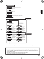
222222 Special tools for R410A
Tool name
Contents of change for R22 tool
Gauge manifold
Pressure is huge and cannot be measured with a conventional gauge. To prevent
erroneous mixing of other refrigerants, the diameter of each port has been changed.
It is recommended to use a gauge manifold with a high pressure display range -0.1 to 5.3
MPa and a low pressure display range -0.1 to 3.8 MPa.
Charging hose
To increase pressure resistance, the hose material and base size were changed.
Vacuum pump
A conventional vacuum pump can be used by installing a vacuum pump adapter.
Gas leakage detector
Special gas leakage detector for HFC refrigerant R410A.
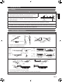
222222 Accessories
Use connecting parts as required.
Do not throw away the connecting parts until the installation has been complete.
Name and shape
Specifications
manual
Installation
manual
Q’ty
Application
—
Name and shape
1
1
(This book)
1
Joint pipe A
1
Q’ty
Joint pipe B
Binder
9
Application
For connecting gas pipe
(L type)
For binding power cable
and transmission cable
For connecting gas pipe
(Straight type)
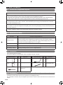
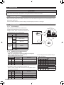
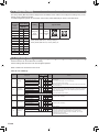
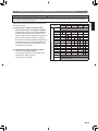
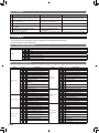
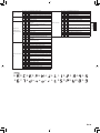
222222 Combinations
A maximum of three outdoor units can be connected to one refrigerant system.
The combination of outdoor units per refrigerant system and the number of indoor units that can be connected are as
follows:
En-4
Outdoor Unit
Nominal System Capacity (HP)
8
10
12
14
16
Installation space combination
Combination (HP)
Outdoor Unit 1 (HP)
Outdoor Unit 2 (HP)
8
8
-
10
10
-
12
12
-
14
14
-
16
16
-
18
10
8
20
12
8
22
12
10
24
12
12
26
14
12
28
16
12
30
16
14
32
16
16
34
12
12
36
12
12
38
14
12
40
16
12
42
16
14
44
16
16
46
16
16
48
16
16
Outdoor Unit 3 (HP)
-
-
-
-
-
-
-
-
-
-
-
-
-
10
12
12
12
12
12
14
16
15
16
17
21
24
32
32
32
35
39
42
45
48
48
48
48
48
48
48
48
48
Maximum Connectable
Indoor Unit
When connecting outdoor units, install the outdoor unit with the largest nominal system capacity nearest to the refrigerant pipe
and indoor unit, followed by those with lesser nominal system capacities. (Outdoor unit 1 <
= Outdoor unit 2 <
= Outdoor unit 3)
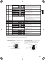
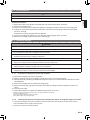
Energy-saving combination
Combination (HP)
Outdoor Unit 1 (HP)
Outdoor Unit 2 (HP)
Outdoor Unit 3 (HP)
Maximum Connectable
Indoor Unit
8
-
10
-
12
-
14
-
16
8
8
-
18
-
20
-
22
14
8
-
24
8
8
8
26
10
8
8
28
12
8
8
30
14
8
8
32
12
12
8
34
14
12
8
36
14
14
8
38
-
40
14
14
12
42
14
14
14
44
16
14
14
46
-
48
-
*
*
*
*
30
*
*
33
36
39
42
45
48
48
48
*
48
48
48
*
*
* means that the energy-saving combination is unavailable.
When connecting outdoor units, install the outdoor unit with the largest nominal system capacity nearest to the refrigerant pipe
and indoor unit, followed by those with lesser nominal system capacities. (Outdoor unit 1 >
= Outdoor unit 2 >
= Outdoor unit 3)
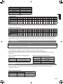
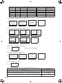
222222 Option parts
CAUTION
The following parts are optional parts specific to R410A refrigerant.
Do not use parts other than those listed below.
222222222
Separation tube kit
Table A indicates the separation tube to be used when installing multiple outdoor units.
Table B indicates the separation tube to be used for connecting the outdoor and indoor units.
Refer to the installation instruction sheet for the outdoor unit branch kit and the separation tubes for installation
specifications.
TTTTTTTA Separation tube for installing multiple
outdoor units
Separation tube
UTR-CP567X
Total cooling capacity of
indoor unit (kw)
ALL
TTTTTTTB Selection of separation tubes
Separation tube
UTR-BP090X
UTR-BP180X
UTR-BP567X
Total cooling capacity of
indoor unit(kW)
28.0 or less
28.1 to 56.0
56.1 or more
222222 Header
A header is used for connecting the indoor units. Refer to the installation instruction sheet for the header for
installation specifications.
TTTTTTTC Selection of header
Header
3-6 Branches
3-8 Branches
UTR-H0906L
UTR-H1806L
UTR-H0908L
UTR-H1808L
Total cooling capacity of
indoor unit (kw)
28.0 or less
28.1 to 56.0
En-5
English
Model Name
AJ A72LALH
AJ A90LALH
AJ 108LALH
AJ 126LALH
AJ 144LALH
333 INSTALLATION WORK
Please obtain the approval of the customer when selecting the location of installation and installing the main unit.
333333 Selecting an installation location
WARNING
•• Install the unit in a location that can withstand its weight, and where it will not topple or fall.
•• Calculate the proper refrigerant concentration if you will be installing it in an enclosed location.
Total amount of replenished refrigerant in refrigerant facility (kg) >
=
Refrigerant concentration(kg/m3)
(0.3kg/m3)
Capacity of smallest room where unit is installed (m ) •• If the results of the calculation exceed the concentration limit, increase the room surface area or install a ventilation duct.
3
CAUTION
Select an installation location by observing the following precautions:
•• Install the unit horizontally.(within 3 degrees)
•• Install this unit in a location with good ventilation.
•• If the unit must be installed in an area within easy reach of the general public, install as necessary a protective
fence or the like to prevent their access.
•• Install the unit in an area that would not inconvenience your neighbors, as they could be affected by the airflow
coming out from the outlet, noise, or vibration.
If it must be installed in proximity to your neighbors, be sure to obtain their approval.
•• If the unit is installed in a cold region that is affected by snow accumulation, snow fall, or freezing, take
appropriate measures to protect it from those elements.
To ensure a stable operation, install inlet and outlet ducts.
•• Install the unit in an area that would not cause problems even if the drain water is discharged from the unit.
Otherwise, provide drainage that would not affect people or objects.
•• Install the unit in an area that has no heat sources, vapors, or the risk of the leakage of flammable gas in the vicinity.
•• Install the unit in an area that is away from the exhaust or vent ports that discharge vapor, soot, dust, or debris.
•• Install the indoor unit, outdoor unit, power supply cable, transmission cable and remote control cable at least 1
meter away from a television or radio.
The purpose of this is to prevent TV reception interference or radio noise. (Even if they are installed more than 1
meter apart, you could still receive noise under some signal conditions.)
•• Keep the length of the piping of the indoor and outdoor units within the allowable range.
•• For maintenance purposes, do not bury the piping.
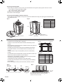
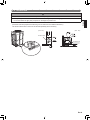
333333 Drain processing
•• The drain water is discharged from the bottom of the equipment. Construct a drain ditch around the base and
discharge the drain water properly.
•• When installing on a roof, perform floor waterproofing properly.
Drain processing:
•• The drain water from the base of the outdoor unit may
generate during operations.
Perform drain processing, as necessary.
•• When you want to prevent the drain water from leaking at the
perimeter, construct a ditch for the drain water as shown in the
figure.
•• Provide a central drain pan, as necessary.
En-6
Outdoor unit
50 mm
or more
10 mm or
more
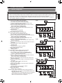
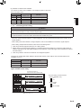
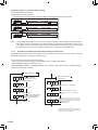
333333 Installation dimensions
CAUTION
When installing the outdoor unit, pay attention to the following items.
English
•• Provide sufficient installation space, such as transportation route, maintenance space, ventilation space,
refrigerant piping space, and passageways.
•• Pay attention to the specifications of the installation space as shown in the figure. If the unit is not installed
according to specifications, it may cause short circuit or poor performance. The unit may be prone to lapse into
non-operation due to high pressure protection.
•• Do not place obstructions in the air flow outlet direction. If there is an obstruction in the outlet direction, install an outlet duct.
•• When there is a wall in front of the unit, provide a space of 500mm or more as maintenance space.
•• When there is a wall at the left side of the unit, provide a space of 30mm or more as maintenance space.
•• An outdoor temperature of 35 degrees in air-conditioned operation is assumed for the installation space in this item.If the outdoor
temperature exceeds 35 degrees and the outdoor unit is operating at a load exceeding its rated ability, provide a larger inlet space.
•• If you are installing more outdoor units than indicated here, please ensure sufficient space or consult your
distributing agent as it may affect the performance due to short circuit and other problems.
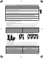
333333333
When install near by limited height wall
(((( Single and multiple installations
•• There are no restrictions on the height of the side wall.
•• Provide installation spaces L1 and L2 in accordance with the table below according to the wall height (front side, rear
side) conditions.
•• Provide installation spaces other than L1 and L2 in accordance with the conditions shown in the figure below.
•• Ventilation resistance can be ignorable when the distance from a wall or product, etc. is larger than 2m.
FFFFF1
Necessary installation space
When H1 is 1500(mm) or less
L1 >
= 500(mm)
When H1 is 1500(mm) or more
L1 >
= 500+h1÷2(mm)
When H2 is 500(mm) or less
L2 >
= 100(mm)
When H2 is 500(mm) or more
L2 >
= 100+h2÷2(mm)
FFFFF2 Single installation
<Side view>
L2
L1
30mm or more 10mm or more
Wall
<Top view>
L2
<Rear>
L1
<Front>
H2
<Front>
500 h2
h1
<Rear>
L1
FFFFF3 Multiple installations
<Top view>
<Rear>
H1
1500
<Front>
Wall height condition
L2
30mm or
more
20mm or
more
20mm or
more
10mm or
more
Wall
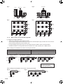
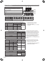
(((( Concentrated installation
•• Provide installation spaces L3, L4, and L5 in accordance with the table below according to the wall height (front
side, rear side) conditions.
•• Provide installation spaces other than L3, L4, and L5 in accordance with the conditions shown in the figure below.
•• Ventilation resistance can be ignorable when the distance from a wall or product, etc. is larger than 2m.
Wall height condition
Necessary installation space
When H3 is 1500(mm) or less
L3 >
= 500(mm)
When H3 is 1500(mm) or more
L3 >
= 500+h3÷2(mm)
When H4 is 500(mm) or less
L4 >
= 200(mm)
When H4 is 500(mm) or more
L4 >
= 200+h4÷2(mm)
When H5 is 500(mm) or less
L5 >
= 200(mm)
When H5 is 500(mm) or more
L5 >
= 200+h5÷2(mm)
En-7
FFFFF4
<Side view>
FFFFF5
<Rear>
<Front view>
L3
L5
Wall
L5
Wall
Wall
FFFFF7
<Top view>
<Top view>
L4
L4
800mm
or more
500mm
or more
800mm
or more
1000mm
or more
L3
L5
333333333
20mm or
more
20mm or
more
H5
500 h5
H5
500 h5
L4
Wall
FFFFF6
H4
500 h4
H3
1500
h3
<Front>
L3
L5
20mm or
more
L5
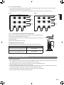
When install near by unlimited height wall
20mm or
more
L5
(((( Single and multiple installations
•• There are no restrictions on the height of the wall.
•• The wall (without height restrictions) must not exist on the both sides (left / right) of outdoor unit. Also, must not
exist on the both sides (front / rear) of outdoor unit.
•• Provide installation spaces other than L6 in accordance with the conditions shown in the figure below.
•• Ventilation resistance can be ignorable when the distance from a wall or product, etc. is larger than 2m.
When installing with the REAR of the outdoor unit facing the wall side
Condition
Necessary installation space
When B >
= 400 (mm)
When
20 <
=B
FFFFF8 Single installation
<Top view>
L6 >
= 200 (mm)
L6 >
= 200 + (400-B) ×3 (mm)
< 400 (mm)
FFFFF9 Multiple installations
<Top view>
100mm
or more <Rear>
<Rear>
800mm
or more
L6
<Front>
<Front>
200mm
or more
200mm
or more
B
200mm
or more
B
200mm
200mm
Example :
When B is made 200mm
L6 >
= 200+(400-200)×3=800mm
When installing with the FRONT of the outdoor unit facing the wall side
FFFFF10 <Top view> Wall
FFFFF11
<Top view>
Wall
500mm
or more
<Rear>
Wall
FFFFF
<Front>
200mm or more
En-8
200mm
or more
20mm or
more
20mm or
more
Wall
500mm
or more
(((( Concentrated Installation
•• The wall (without height restrictions) must not exist on the both sides (left / right) of outdoor unit. Also, must not
exist on the both sides (front / rear) of outdoor unit.
•• Ventilation resistance can be ignorable when the distance from a wall or product, etc. is larger than 2m.
FFFFF12
FFFFF13
400mm
or more
400mm
or more
500mm
or more
800mm
or more
1000mm
or more
800mm
or more
1000mm
or more
333333333
400mm
or more
400mm
or more
1000mm
or more
400mm
or more
400mm
or more
When there are obstacles above the product
When there are obstacles above the product, keep the minimum installation height
as shown in the figure and install the outlet duct.
When installing the outlet duct, you must set the high static pressure mode with the
push-button switch.
(Similar when installing anti-snow hood)
Setting high static pressure mode
Follow the instructions in the table below to set the high static pressure mode.
Condition
High static pressure mode setting *1
When L <
= 150mm and other resistance
is not at the air flow outlet (30Pa or less)
Set to Mode 1
When L>150mm or other resistance
is at the air flow outlet (80Pa or less)
Set to Mode 2
Outlet duct
500mm
or more
L
**** Refer to the section on Push Switch Setting in “Chapter 7 Field Setting”.
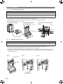
333333 Transportation the outdoor unit
Hoisting method (Fig. A)
•• When hanging the outdoor unit and conveying it to installation location, hang the unit with rope by passing through
the 4 opening holes on bottom of front and rear side as shown in figure.
•• Use 2 ropes at least 8m long. If used shorter length, it may cause to damage the unit.
•• Use the sufficiently strong rope to bear the unit’s weight.
•• Place the protective board or filler cloth at the place where the cabinet may come into contact with rope to prevent
from damages. Without using them, cabinet may cause to damage or deform.
•• During the hanging unit, make sure to keep the unit horizontally to prevent the drop.
•• Be careful not to shock the impacts during the hanging.
En-9
English
<Top view>
<Top view>
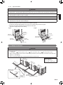
Conveying by forklift (Fig.B)
•• When using the forklift to convey the unit, pass the forklift arms through the opening space as shown in below.
Front : Bottom of the wooden delivery pallet.
Side : Space between pallet and cabinet.
•• Enable to remove the pallet from cabinet.
•• Be careful not to be damaged.
Conveying by forklift (Manual forklift: hand-fork)
•• When using the manual forklift to convey the unit, pass the forklift arms through the opening space between pallet
and cabinet from side.
FFFFFA
FFFFFB
Product mass (kg)
<Side>
<Front>
Fork(Forklift)
opening space
protective boards
AJ□A72LALH
220
AJ□A90LALH
220
AJ□108LALH
275
AJ□126LALH
296
AJ□144LALH
296
Fork(forklift) or
Fork(Manual forklift)
Delivery pallet
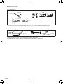
333333 Installation the unit
FFFFFB
NO GOOD
OK
OK
FFFFFA
(Unit:mm)
160
160
732
765
•• Install the unit horizontally.(within 3 degrees).
•• Install 4 or more anchor bolts at the 8 locations indicated by arrows
(Fig. A).
•• Place the left and right anchor bolts at a distance further away than the
dimensions of A in the Table A.
(Excluding the case where anchor bolts are installed at 8 locations.)
•• To minimize vibration, do not install the outdoor unit directly on the
ground.
Instead, install it on top of a firm platform (such as concrete block).
(Fig. B)
•• The foundation base should be able to support the product and the foot
width of the product should be more than 46.5mm.
•• Depending on the installation condition, vibration during the operation
of the unit may cause noise and vibration.
Install vibration-proofing materials (such as rubber pads).
•• Consider the removal space of the connection piping when installing
the foundation.
•• Secure the equipment firmly with anchor bolts, washers, and nuts.
Bottom view
8-12×17 (hole)
TTTTTTTA
AJ□A72LALH
Model name
A
B
610
930
610
930
AJ□108LALH
610
930
920
1240
AJ□144LALH
920
1240
AJ□A90LALH
AJ□126LALH
FFFFFC
Bolt(M10)
More than
200mm
*Do not use a four-corner support foundation.
When installing piping from the bottom of the outdoor units,
the required space under the outdoor unit >
= 200mm.
*Install the branch kit horizontally.
En-10
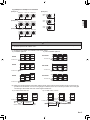
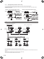
444 SYSTEM CONFIGURATION
444444 System configuration
In case of one outdoor unit connected
•• From outdoor unit to the farthest indoor unit:
a+f <
= 150m, a+p <
= 150m (actual pipe length)
•• From the first separation tube to the farthest indoor unit:
f<
= 60m, p <
= 60m (actual pipe length)
•• Difference in height between outdoor units and indoor units (H1)
50m: For the indoor unit stated below
40m: For the outdoor unit stated below
•• Difference in height between indoor units and indoor units
H2 <
= 15m, H3 <
= 15m
•• Total pipe length
a+f+h+j+l+n+p+q+s+u <
= 700m
•• Total refrigerant amount <
= 31.5kg
FFFFFA
Outdoor
unit
(Master)
h
j
n
Indoor
unit
Indoor
unit
Indoor
unit
H1
Indoor
unit
p
q
s
Indoor
unit
u
Indoor
unit
H2
Indoor
unit
H3 Indoor
unit
FFFFFB
Outdoor
unit 1
(Master)
Outdoor
unit 2
(Slave)
H4
a
b
e
f
h
j
l
Indoor
unit
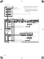
In the case of three outdoor units connected
•• From outdoor unit to the farthest indoor unit:
a+e+f <
= 150m, a+e+p <
= 150m (actual pipe length)
•• From the first separation tube to the farthest indoor unit:
f<
= 60m, p <
= 60m (actual pipe length)
•• Difference in height between outdoor units and indoor units (H1)
50m: For the indoor unit stated below
40m: For the outdoor unit stated below
•• Difference in height between indoor units and indoor units (H2,H3)
H2 <
= 15m, H3 <
= 15m
•• Difference in height between outdoor unit and outdoor units (H4)
H4 <
= 0.5m
•• From outdoor unit to outdoor unit branch kit
a<
= 3m, b <
= 3m, c <
= 3m
•• Between the farthest outdoor unit to the first outdoor unit branch kit
b+d <
= 12m, c+d <
= 12m
•• Total pipe length
a+b+c+d+e+f+h+j+l+n+p+q+s+u <
= 1000m
•• Total refrigerant amount <
= 94.5kg
•• Outdoor unit capacity
Master >
= slave 1 >
= slave 2
NNNNNN • If the outdoor temperature during cooling operation is
expected to be –5 °C or less, do not install the outdoor unit
lower than the indoor unit.
・Please refer to “8.3.2. Checking total amount of refrigerant
and calculating the amount of refrigerant charge to be
added” for the total amount of refrigerant.
l
Indoor
unit
In case of two outdoor unit connected
•• From outdoor unit to the farthest indoor unit:
a+e+f <
= 150m, a+e+p <
= 150m (actual pipe length)
•• Difference in height between outdoor units and indoor units (H1)
50m: For the indoor unit stated below
40m: For the outdoor unit stated below
•• From the first separation tube to the farthest indoor unit
f<
= 60m, p <
= 60m (actual pipe length)
•• Difference in height between indoor units and indoor units (H2, H3)
H2 <
= 15m, H3 <
= 15m
•• Difference in height between outdoor unit and outdoor units (H4)
H4 <
= 0.5m
•• From outdoor unit to outdoor unit branch kit
a<
= 3m, b <
= 3m
•• Total pipe length
a+b+e+f+h+j+l+n+p+q+s+u <
= 1000m
•• Total refrigerant amount <
= 63kg
•• Outdoor unit capacity
Master >
= slave
a
f
n
Indoor
unit
Indoor
unit
Indoor
unit
Indoor
unit
H1
p
q
s
Indoor
unit
Indoor
unit
u
H2
Indoor
unit
H3 Indoor
unit
FFFFFC
Outdoor
unit 1
(Master)
Outdoor
unit 2
(Slave 1)
Outdoor
unit 3
(Slave 2)
H4
a
b
c
d
e
f
j
h
Indoor
unit
l
Indoor
unit
H1
n
Indoor
unit
Indoor
unit
Indoor
unit
p
q
Indoor
unit
s
Indoor
unit
u
H2
Indoor
unit
H3
Indoor
unit
En-11
English
CAUTION
•• When connecting multiple outdoor units, set the nearest outdoor unit to the indoor unit on the refrigerant pipe as the master unit.
•• When connecting multiple outdoor units, install the outdoor unit with the largest nominal system capacity nearest
to the indoor unit and on the refrigerant pipe, followed by those with less nominal system capacities.
•• Always keep to the limit on the total amount of refrigerant.Exceeding the limit on the total amount of refrigerant
when charging will lead to malfunction.
444444 Pipe selection
CAUTION
Master
unit
Slave
unit1
Slave
unit2
•• This unit is designed specifically for use with the
R410A refrigerant.
Pipe size
(table B)
•• Pipes for R407C or R22 may not be used with this
unit.
First separation Outdoor unit
tube (optional) branch
kit (optional)
Separation tube
(optional)
•• Do not use existing pipes.
Pipe size
(table C)
Pipe size
(table D)
Pipe size
(table E)
•• Improper pipe selection will degrade performance.
Indoor
unit
Indoor
unit
Indoor
unit
Indoor
unit
Indoor
unit
Indoor
unit
TTTTTTTA (Wall thickness and pipe material for each diameter)
Outside Diameter
mm
6.35
9.52
Wall Thickness*3
mm
0.8
0.8
Material
12.70
15.88
19.05
0.8
1.0
1.2
COPPER*1
JIS H3300 C1220T-O or equivalent
22.22
28.58
34.92
41.27
1.0
1.0
1.2
1.43
COPPER*2
JIS H 3300 C1220T-H or equivalent
Please select the pipe size in accordance with local rules.
TTTTTTTB (Between outdoor unit to outdoor unit branch kit)
Outside diameter (mm)
HP
Outdoor unit cooling
capacity (kW)
Liquid pipe
8
22.4
12.70
22.22
10
28.0
12.70
22.22
12
33.5
12.70
28.58
Gas pipe
14
40.0
12.70
28.58
16
45.0
12.70
28.58
Branch kit*4
Outside diameter (mm)
Total cooling capacity
of outdoor unit (kW)
Liquid pipe
Gas pipe
22.4 to 28.0
12.70
22.22
28.1 to 45.0
12.70
28.58
45.1 to 56.0
15.88
28.58
56.1 to 80.0
15.88
34.92
80.1 to 96.0
19.05
34.92
96.1 or more
19.05
41.27
TTTTTTTD (Between separation tubes)
Outside diameter (mm)
Liquid pipe
Gas pipe
9.52
15.88
9.52
19.05
14.0 to 28.0
12.70
22.22
28.1 to 44.7
12.70
28.58
44.8 to 56.0
15.88
28.58
11.2 to 13.9
56.1 to 80.0
15.88
34.92
80.1 to 95.0
19.05
34.92
95.1 or more
19.05
41.27
Separation
tube*5
Header
UTR-BP090X
UTR-H0906L
UTR-H0908L
UTR-BP180X
UTR-H1806L
UTR-H1808L
UTR-BP567X
—
*5
TTTTTTTE (Between separation tube to indoor unit)
Liquid pipe
2.2, 2.8, 3.6, 4.0, 4.5
6.35
5.6, 7.1, 8.0, 9.0
11.2, 12.5, 14.0, 18.0
22.4, 25.0
En-12
Outside diameter (mm)
Cooling capacity of
indoor unit (kW)
9.52
12.70
Allowable tensile stress >
= 33 (N/mm2)
Allowable tensile stress >
= 61 (N/mm2)
Design pressure 4.15MPa
For the installation method, refer to “5.4. Multiple
connections”.
UTRCP567X
TTTTTTTC (Between outdoor unit branch kits or outdoor unit
branch kit to first separation tube)
Total cooling
capacity of
indoor unit
(kW)
4.4 to 11.1
****
****
****
****
Gas pipe
12.70
15.88
19.05
22.22
If the pipe diameter between separation
tubes (based on Table D) is larger than the
pipe diameter between outdoor unit branch
kit and the first separation tube (based on
Table C), select the pipe whose diameter is
equal to the one between the outdoor unit
branch kit and the first separation tube.
(If pipe diameter D > C, select pipe size from
table C)
Use a standard separation tube for pipe
branching. Do not use a T tube as it does
not separate the refrigerant evenly.
**** For the installation method, refer to the installation
manuals for indoor unit piping connection,
separation tubes, and header.
555 PIPE INSTALLATION
555555 Brazing
CAUTION
FFFFF
Pressure regulating valve
Cap
•• Apply nitrogen gas while brazing the pipes.
Nitrogen gas pressure: 0.02 MPa (= pressure felt sufficiently on the
back of your hand)
English
•• If air or another type of refrigerant enters the refrigeration cycle, the
internal pressure in the refrigeration cycle will become abnormally
high and prevent the unit from exerting its full performance.
Nitrogen gas
Brazing area
•• If a pipe is brazed without applying nitrogen gas, it will create an oxidation film.
This can degrade performance or damage the parts in the unit (such as the compressor or valves).
•• Do not use flux to braze pipes. If the flux is the chlorine type, it will cause the pipes to corrode.
In addition, if the flux contains fluoride, it will affect the refrigerant piping system due to deterioration of refrigerant oil.
•• For brazing material, use phosphor copper that does not require flux.
555555 Indoor unit pipe connections
CAUTION
Separation tube
B
Horizontal
A
B
Vertical
A
or
Horizontal line
±15°C
NO GOOD
OK
B
A
A : Outdoor unit or Refrigerant branch kit
B : Indoor unit or Refrigerant branch kit
Header
Gas pipe
Outdoor
unit side
Horizontal
line
C
H1
Horizontal (A1 : 0o – 1o)
line
B1: -10o – 10o
VIEW C
A1
Horizontal
Horizontal
line
line
Liquid pipe
Outdoor
unit side
H1 = 0 mm –
10 mm
B1
D
H2
A2
B2
OK
Main pipe
VIEW D
0.5m or more
To indoor unit
Main pipe
0.5m or more
To indoor unit
Separation tube
or
Header
H2 = 0 mm –
10 mm
(A2 : 0o – 1o)
B2: -10o – 10o
To indoor
unit
NO GOOD
Separation tube
0.5m or more
To indoor
unit
or
Header
0.5m or more
To indoor unit
NO GOOD
To indoor unit
•• Do not connect a separation tube after a header.
•• Leave the distance 0.5 m or more for straight part to branch tube and header.
•• For details, refer to the Installation Instruction Sheet of each part.
En-13
555555 Piping method
555555555
Opening the knockout hole
CAUTION
•• Be careful to prevent panel deformed or damaged while opening the knockout hole.
•• To prevent cutting of the wiring after the knockout hole was opened, remove the burrs along the edge.
•• In addition, to prevent rusting, painting the edge with rust preventive paint is recommended.
The piping can be connected from two directions; the front or the bottom.
(Knockout holes are provided so that the piping can be connected from two different directions.)
Use the front knockout hole, as required.
FFFFFA Knockout position
FFFFFB Detail of knockout
position (bottom)
FFFFFC Detail of knockout position
(front)
(Unit:mm)
(Unit:mm)
Knockout
hole
Knockout hole
555555555
Removing the pinch pipe
WARNING
Remove the pinch pipe only when the internal gas is completely drained.
If gas still remains inside, the piping may crack if you melt the brazing filler metal of the junction area with a burner.
Before connecting the piping, remove the pinch pipe in accordance with the following instructions:
Verify that the liquid side and gas side 3-way valves are closed. (Fig. A)
Cut the end of the liquid side and gas side pinch pipe and vent the gas inside the pinch pipe. (Fig. B)
After all the gas is vented, melt the brazing filter metal on connecting part using a burner and remove the
pinch pipe. (Fig. C)
FFFFFA
3-way valve
FFFFFB
pinch pipe
end of pinch pipe
En-14
FFFFFC
555555555
Pipe connection
CAUTION
•• Seal the pipe route hole with putty (field supply) such that there are no gaps.
Small insects or animals that are trapped in the outdoor unit may cause a short circuit in the electrical component box.
English
•• To prevent pipe damage; do not make sharp bends in the pipe.
Bend the pipe at a radius of 70mm or greater.
•• Do not bent pipe many times at same part to prevent break.
•• Do not use flare connection on the indoor unit pipe until the connection piping has been connected.
•• Wait until the 3-way valve is completely cooled down before removing the pinch pipe or brazing the joint pipe.
Otherwise, the 3-way valve may be damaged.
•• Blaze the joint pipe onto the 3-way valves at the liquid and gas side.
Process the joint pipe appropriately so that it can be connected easily with the main pipe.
•• Blaze the joint pipe at the liquid and gas side with the main pipe.
* Be sure to supply nitrogen when blazing.
FFFFFA
FFFFFB
joint pipe
(accessory)
joint pipe
(Field supply)
joint pipe
(accessory)
knockout
hole
joint pipe
(Field supply)
Gas pipe
(Field supply)
Liquid pipe
(Field supply)
knockout
hole
To indoor unit
555555 Multiple connections
CAUTION
•• When connecting multiple (maximum three) units, be sure to install the unit with the largest capacity nearest to
the indoor unit.
For example) AJ 126LALH (Outdoor Unit1) + AJ 126LALH (Outdoor Unit2) + AJ A90LALH (Outdoor Unit3)
•• When connecting multiple units, set the unit with the largest capacity as the master unit, and the rest as the slave units.
(Refer to 7. Field Setting)
•• When connecting multiple units, use the optional outdoor unit branch kit.
Ou
(Ma tdoor
ste unit
r un 1
it)
To
ind
oo
r
Ou
(Sl tdoor
ave un
uni it 2
t 2)
un
it
Outdoor Capacity
2 Unit : Unit1 >
= Unit2
3 Unit : Unit1 >
= Unit2 >
= Unit3
Ou
(Sl tdoor
ave un
uni it 3
t 2)
To indoor unit
(To main pipe)
To outdoor unit
To outdoor unit
Outdoor unit
branch
kit (Optional)
Liquid pipe
(Field supply)
Gas pipe (Field supply)
Joint pipe
(Accessory)
En-15
Restriction when install
Be sure following restriction.
Installation angle
Outdoor unit branch kit
A
Horizontal
To indoor unit
To outdoor unit
C
B
No good
No good
No good
OK good
0 to -10
No od
go
No
OK
A
C
No od
go
No
good
To outdoor unit
or next branch kit
0 to -10
Vertical
B
•• Install the outdoor unit branch kit horizontally, within 0° to -10°, so that the refrigerant separates evenly.
•• Do not install the outdoor unit branch kit vertically.
Straight pipe length
To indoor unit
(To main pipe)
To outdoor unit
To indoor unit (To main pipe)
To outdoor unit
To outdoor unit
0.5m or more
0.5m or more
To outdoor unit
•• Leave the distance 0.5m or more for straight part to outdoor unit branch kit.
For details, refer to the Installation Instruction Sheet of the outdoor unit branch kit.
En-16
To outdoor
unit
FFFFFExamples of multiple unit installation
(Example 1)
Master unit
Slave unit1 Slave unit2
(Example 4)
Master
unit
(Example 3)
Master unit
Slave unit1 Slave unit2
Slave
unit1
English
(Example 2)
Slave
unit2
Master unit
Slave unit1 Slave unit2
CAUTION
To prevent the oil from settling in the stopped unit, install the pipes between the outdoor units so that they are level
or are tilted upward to the outdoor units.
(((( Examples of multiple unit installation are shown below.
Installable patterns
Non-installable patterns
GOOD
Master
unit
Slave
unit 1
Slave
unit 2
NO GOOD
Master
unit
Slave
unit 1
Slave
unit 2
NO GOOD
Slave
unit 2
Master
unit
Slave
unit 1
Slave
unit 2
Master
unit
Slave
unit 1
Slave
unit 2
To indoor unit
To indoor unit
GOOD
Slave
unit 1
To indoor unit
To indoor unit
GOOD
Master
unit
Slave
unit 1
Master
unit
Slave
unit 2
NO GOOD
To indoor unit
To indoor unit
(((( When the length between branch kits and the length of the branch kit and outdoor units is more than 2m,
provide a rise of 200mm or more on the gas pipe. However, there is no need to provide a rise on the pipe
connecting to the master unit even if the length exceeds 2m.
In case of less than 2m
In case of 2m or more
Master
unit
Slave
unit 1
Slave
unit 2
To indoor unit
To indoor unit
Less than 2 m
Outdoor unit branch kit
Master
unit
Gas
pipe
Slave
unit2
Slave
unit1
Outdoor unit
branch kit
2 m or less
2 m or more
Rise
200 mm or more
Gas pipe
En-17
666 ELECTRICAL WIRING
666666 The precautions of electrical wiring
WARNING
•• Wiring connections must be performed by a qualified person in accordance with specifications.
The rated supply of this product is 50Hz, 400V of 3-phase, 4-wire. Use a voltage within the range of 342-456V.
•• Before connecting the wires, make sure the power supply is OFF.
•• Select a breaker (earth leakage breaker) of appropriate capacity and install one at every power supply of an
outdoor unit.Wrong selection of breakers (earth leakage breakers) or transition wiring will lead to electric shock
and fire.
•• Do not connect AC power supply to the transmission line terminal board.
Improper wiring can damage the entire system.
•• Install a breaker (earth leakage breaker) in accordance with the related laws and regulations.
•• Connect the connector cord securely to the terminal.
Faulty installation can cause a fire.
•• Make sure to secure the insulation portion of the connector cable with the cord clamp. A damaged insulation can
cause a short circuit.
•• Never install a power factor improvement condenser. Instead of improving the power factor, the condenser may overheat.
•• Before servicing the unit, turn the power supply switch OFF. Then, do not touch electric parts for 10 minutes due
to the risk of electric shock.
•• Make sure to perform grounding work.Improper grounding work can cause electric shocks.
CAUTION
•• The primary power supply capacity is for the air conditioner itself, and does not include the concurrent use of other devices.
•• Connect the power cables in positive phase sequence.If they are connected in negative phase sequence, an
error will be displayed.If there is a missing phase connection, the unit will not operate normally.Do not connect a
N phase (neutral phase) cable to other phases (misconnection).Wrong wiring will lead to parts damage.
•• Do not use crossover power supply wiring for the outdoor unit.
•• If the electrical power is inadequate, contact your electric power company.
•• Install a breaker (earth leakage breaker) in a location that is not exposed to high temperatures.
If the temperature surrounding the breaker (earth leakage breaker) is too high, the amperage at which the breaker
(earth leakage breaker) cuts out may decrease.
•• Use a breaker (earth leakage breaker) that is capable of handling high frequencies. Because the outdoor unit is
inverter controlled , a high-frequency earth leakage breaker is necessary to prevent a malfunction of the breaker
itself.
•• When the electrical switchboard is installed outdoors, place it under lock and key so that it is not easily accessible.
•• Do not fasten the power supply cable and transmission cable together.
•• Always keep to the maximum length of the transmission cable.Exceeding the maximum length may lead to
erroneous operation.
•• The static electricity that is charged to the human body can damage the control PC Board when handling the
control PC Board for address setting, etc.
Please keep caution to the following points.
Provide the grounding of Indoor unit, Outdoor unit and Option equipment.
Cut off the power supply (breaker).
Touch the metal section (such as the unpainted control box section) of the indoor or outdoor unit for more than
10 seconds. Discharge the static electricity in your body.
Never touch the component terminal or pattern on the PC Board.
En-18
666666 Knockout hole
CAUTION
•• Be careful not to deform or scratch the panel while opening the knockout holes.
English
•• After opening the knockout hole, remove the burr on the edges to prevent snapping of wires.
It is recommended to apply rust proof paint on the edges to prevent rust.
Electric wires can be connected from the front or from the left.
(Knockout holes are prepared so that wiring can be made from two different directions.)
Use the knockout holes on the front and the left separately when necessary.
(Unit : mm)
(Unit : mm)
knockout hole
knockout hole
En-19
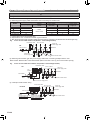
666666 Selecting power supply cable and breaker
CAUTION
•• Regulation of wire size and circuit breaker differs from each locality, please refer in accordance with local rules.
Refer to the table for the wiring and breaker specifications of each installation condition.
(((( Selecting power supply cable and breaker when connecting one outdoor unit
MODEL
AJ A72LALH
Breaker (Time delay fuse or circuit capacity)
leakage
Capacity (A)
current
30
AJ A90LALH
30
AJ 108LALH
50
AJ 126LALH
50
AJ 144LALH
50
Outdoor unit power supply cable
Power supply
Critical wiring
Ground wire (mm2)
cable (mm2)
length (m)
4
4
30
100mA
0.1sec or less
4
4
30
10
6
42
10
6
42
10
6
42
These values are recommended data.
Specification: Use conformed cord with Type 245 IEC57
Max. wire length: Set a length so that the voltage drop is less than 2%. Increase the wire diameter when the wire length is long.
FFFFF In case of connected outdoor unit (breaker : earth leakage breaker)
Transmission cable
230 V 1ø 50 Hz
Indoor unit
Power supply cable
OK
Breaker
400 V 3ø 50 Hz
Breaker
Outdoor unit
Power supply cable
Remote controller cable
(((( Selecting main breaker and main power supply cable when connecting multiple outdoor units
Main breaker: Main breaker >
= Total Sub breaker (Refer to the table in item (1) for the sub breaker capacity)
FFFFF In case of connected three outdoor unit (breaker : earth leakage breaker)
Transmission cable
OK
230 V 1ø 50 Hz
Sub
breaker
Indoor unit
Power supply cable
Breaker
Main breaker
400 V 3ø
50 Hz
Remote controller cable
Outdoor unit Power supply cable
(((( Example of bad breaker wiring
Transmission cable
No Good
230 V 1ø 50 Hz
Indoor unit
Power supply cable
Breaker
400 V 3ø 50 Hz
Outdoor unit
Breaker
No Good: install a breaker Power supply cable
No Good: crossover power
for each outdoor unit
supply wiring prohibited
En-20
Remote controller cable
666666 Transmission line
•• Caution when wiring cable
When stripping off the coating of lead wire, always use
the exclusive tool such as a wire stripper. If there is no
exclusive tool available necessarily, carefully strip the
coating by a cutter etc. so that the conductive wire is
not damaged.
If it is damaged, it may lead to an open circuit and a
communication error.
•• Pay attention to the following points while attaching
wires on the terminal board.
Do not attach 2 wires on one side.
Do not twist wires.
Do not cross the wires.
Do not shorted at edge at root.
666666666
2pcs at one side
Wires twisted
NO GOOD
1 wire
OK
NO GOOD
Shorted at edge
English
CAUTION
2 wires
Shorted at root
OK
NO GOOD
NO GOOD
Transmission wiring specifications
Follow the specifications below for the transmission cable.
Use
Size
Wire type
Remarks
Transmission cable
0.33mm2
22AWG LEVEL 4 (NEMA) non-polar 2core,
twisted pair solid core diameter 0.65mm
LONWORKS®
compatible cable
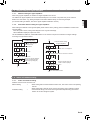
666666666
Wiring rules
(1)Total length of transmission cable
Total transmission line length : MAX 3600m
EF+EG+GH+HJ+HK+KL < 3600m (Fig.2) In the following cases , Signal Amplifier is required. ①When the total length of the transmission line exceeded 500m.
AB+BC+BD > 500m (Fig.1)
②When the total number of units* is over 64.
③Transmission line length between each unit*≧ 400m
(2)Length of transmission cable between one network
segment (NS)
EF+EG+GH+HJ+HK ≦ 500m (Fig.2)
KL ≦ 500m (Fig.2)
(3)Length of transmission cable between outdoor units in a
refrigerant system
MN ≦ 18m
NP ≦ 18m
FFFFF1
Outdoor unit
Transmission line
A
Terminal
resistor
System
C Controller
B
D
Indoor unit
When AB+BC+BD>500m
:Signal Amplifier is required.
Touch
Panel
Controller
FFFFF2
NS 1
Outdoor unit
Indoor unit
F
E
M
NNNNNN Unit* means indoor unit, outdoor unit, Touch Panel
Controller and System Controller, Signal Amplifier,
single split adaptor, Network Convertor etc..
G
H
Terminal resistor
N
Transmission line
P
J
Touch
Panel
Controller
NS 2
L
System
Controller
K
Do not use loop wiring.This may lead to parts damage
and erroneous operation.
Signal Amplifier
Terminal resistor
En-21
666666666
Enabling/Disabling automatic address setting
You can enable/disable automatic address setting for the indoor unit and the signal amplifier.
To enable automatic address setting for the indoor unit, connect the indoor unit to outdoor units under the same
refrigerant system.(Fig.4)
Example : Disable Automatic Address setting
Example : Enable Automatic Address setting
Transmission line
Refrigerant
system 1
Transmission line
Refrigerant
system 1
Transmission line
Refrigerant
system 2
Transmission line
Refrigerant
system 2
Transmission line
Refrigerant
system 3
Transmission line
Refrigerant
system 3
666666 Wiring method
To other refrigerant cricuit Outdoor unit
(breaker : earth leakage breaker)
Power supply
Power supply
L1 L2 L3 N
Outdoor unit1
(Master unit)
Breaker
L1 L2 L3 N
Transmission
Outdoor unit2
(Slave unit 1)
Transmission
Indoor unit
Transmission
Power supply Remote control
Breaker
Breaker
L1 L2 L3 N
Transmission
Power supply
Breaker
L1 L2 L3 N
Transmission
Indoor unit
Transmission
Remote control
Power supply
Remote control
Breaker
Power supply
Remote
control unit
L1 L2 L3 N
Outdoor unit3
(Slave unit 2)
Indoor unit
Breaker
Power supply
Power supply
L1 L2 L3 N
Power supply
Remote
control unit
Remote
control unit
The wiring example for outdoor and indoor units is shown in figure.
Remove the cover of the electrical component box and follow the terminal plate to connect the electric wires to the
terminal.
After connecting the electric wires, secure them with a cable clamp.
Connect the wires without applying excessive tension.
En-22
Binder
English
Power terminal board
40 mm or more
8~10 mm
Secure with a cable clamp as shown in the figure below.
Cable clip
70~
80 mm
90~
100 mm
Ring terminal :M8
Binder
Cable clip
Transmission cable
Power supply cord
Tightening torque
M3 screw
0.5 to 0.6 N·m (5 to 6 kgf·cm)
M8 screw
5.0 to 7.0 N·m (50 to 70 kgf·cm)
** Use a ring terminal to connect the electric wires to the power supply terminal board.
Sealing transmission cable
Connect both ends of the sealed wires of the transmission cable to the earth terminal of the equipment or to the earth
screw near the terminal.
Be very careful that the screws are not overly tightened as the wires may snap and the terminal may be damaged.
Wind with insulation tape to prevent
short circuit
Use one side of the
twisted-pair cable
Connect both ends of sealed
cable to earth.
Be sure to use one side of a twisted-pair cable when using transmission cable with two sets of twisted-pair cables.
En-23
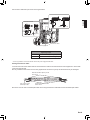
777 FIELD SETTING
CAUTION
Discharge the static electricity from your body before setting up the DIP switches.
Never touch the terminals or the patterns on the parts that are mounted on the board.
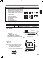
777777 Field setting switches
Remove the front panel of the outdoor unit and the cover of the electrical component box to access the print circuit
board of the outdoor unit.
Print circuit board switches for various settings and LED displays are shown in the figure.
777777 DIP switch setting
777777777
List of Settings
SET3 and SET5 must be set for the DIP switch.
Configure the settings before turning on the power.
Settings for SET1, SET2, and SET4 DIP switches are
factory default ones. Do not change them.
DIP Switch
1-4
Forbidden
SET2
1-4
Forbidden
1
Outdoor unit
address setting
2
3
4
SET4
LED105
Forbidden
1-2
Number of outdoor units
installed
3
Forbidden
4
Terminal resistor setting
Rotary switch
REF AD
LED104
SW106
SW105
X 10
X1
MODE SELECT ENTER
/EXIT
SET 1
SET 2
SET 3
SET 4
SW107 SW108 SW109
SW101
SW102
SW103
SW104
Push button
Setting for number of
slave units
1-4
SET5
POWER
ERROR
MODE
LED101 LED102
(GREEN) (RED)
Function
SET1
SET3
Cable clip 7 Segment
LED Lamp
DIP switch
SET5
Outdoor unit printed circuit board
777777777 Settings to be configured locally
(((( Outdoor unit address setting
When two or three outdoor units are installed to one refrigerant
system, set the address for each outdoor unit.
Set the address for all outdoor units.
SET3
1
2
Outdoor unit
address
Remarks
OFF
OFF
0
Master unit only (Factory setting)
OFF
ON
1
Slave unit 1
ON
OFF
2
Slave unit 2
ON
ON
-
Forbidden
(((( Number of slave units setting for outdoor unit
Set the number of slave units connected to one refrigerant system.
Set only the master unit.
SET3
En-24
3
4
OFF
OFF
ON
ON
OFF
ON
OFF
ON
Number of
connectable
outdoor units
0
1
2
-
Remarks
Master unit only (Factory setting)
1 slave unit connected
2 slave unit connected
Forbidden
Do not change the factory default settings
for SET1 and SET2.
1
OFF
OFF
OFF
OFF
ON
1
OFF
SET1
2
3
OFF
OFF
ON
ON
OFF
OFF
ON
OFF
ON
OFF
SET2
2
3
OFF
OFF
4
Outdoor Unit
Model (HP)
OFF
OFF
OFF
OFF
OFF
8HP model
10HP model
12HP model
14HP model
16HP model
4
OFF
Model Type
Air-conditioner/
Heater fixed type
(((( Number of outdoor units installed
SET5
Number of
outdoor units
Remarks
OFF
1
(Factory setting)
ON
2
-
ON
OFF
3
-
ON
ON
-
Forbidden
1
2
OFF
OFF
777777777
English
The number of outdoor units installed in one refrigerant system must be set.
Set for all outdoor units.
Terminating resistor setting
Caution
Be sure to set the terminal resistor according to specifi cations.
Set the terminal resistor for every network segment (NS).
If terminal resistor is set in multiple devices, the overall communication system may be damaged.
If terminal resistor is not set in a device, abnormal communication may occur.
•• Be sure to set one terminal resistor in a network segment. You can set the terminal resistor at the outdoor unit or
signal amplifi er.
•• When setting the terminal resistor of a signal amplifi er, refer to the installation manual of the signal amplifi er.
•• When setting multiple terminal resistors, take note of the following items.
①① How many network segments are there in a VRF system?
②② Where will you set the terminal resistors in a network segment?(Condition for 1 segment: Total number of
outdoor and indoor units and signal amplifiers is less than 64, or the total length of the transmission cable is
less than 500m)
③③ How many outdoor units are connected to one refrigerant system?
Configure the setting (DIP switch SET5) of the terminal resistor of the outdoor units as shown below from
conditions 1 to 3.
SET5
Terminal resistor
Remarks
OFF
Disable
(Factory setting)
ON
Enable
-
4
Figure: Terminal resistor setting
NS1 (Network segment 1)
(Set terminal resistor at outdoor units)
Terminal resistor : on
Master unit
About the setting of terminal resistor
Outdoor unit(Master unit)
:on
Refrigerant system1
Terminal resistor : off
Master unit
:off
Signal amplifer
Install
Refrigerant system2
Do not install
Master unit
NS2 (Network segment 2)
Refrigerant system3
NS3 (Network segment 3)
NS4 (Network segment 4)
Terminal resister : on
En-25
777777 Rotary switch setting
The rotary switch (REF AD) sets the refrigerant circuit address of the outdoor unit.Configure the settings only on the
master unit of a refrigerant system.
If multiple refrigerant systems are connected, set the rotary switch (REF AD) as shown in the table below.
Rotary
Refrigerant Switch Setting
circuit
REF AD
address
×10
×1
0
0
0
1
0
1
Setting
Setting
range
Refrigerant
circuit
address
0–99
Type of switch
Setting
example
63
2
0
2
3
0
3
REF AD × 10
4
5
・
0
0
・
4
5
・
Rotary Switch (REF AD×1) : Factory setting "0"
Rotary Switch (REF AD×10) : Factory setting "0"
・
・
・
・
97
・
9
・
7
98
9
8
99
9
9
REF AD × 1
777777 Push switch setting
Various functions can be set.Set when necessary.
Perform settings after all indoor units have stopped operation.
Refer to Table A for the items that can be set.
TTTTTTTA: List of Settings
No
0
10
11
12
13
20
En-26
Setting Item
Pipe length
setting
Compressor
sequential start
shift
7 segment LED
First 2
Last 2
digits
digits
Standard pipe (40-65m)
0
0
Short pipe (less than 40m)
0
1
Long pipe 1 (65-90m)
0
This item allows you to adjust the cooling cycle loss due to the length of the
connected pipe.
Set according to the length of the connected pipe.
Set only the master unit for this item.
* The pipe length is the nearest distance from the outdoor unit to the indoor
unit on the pipe line.
This item allows you to delay the start timing of the outdoor units for every
refrigerant system when multiple refrigerant systems have been configured.
You can also limit the start current when multiple refrigerant systems are
activated at the same time.
Set only the master unit for this item.
0
2
0
3
Long pipe 3 (120-151m)
0
4
No shift
Shift 1 (21 seconds)
Shift 2 (42 seconds)
Shift 3 (63 seconds)
0
0
0
0
0
1
2
3
O
0
0
0
0
0
0
0
0
0
0
0
0
1
2
3
0
1
2
3
0
0
1
O
1
0
1
1
1
2
1
3
2
0
Content
O
Long pipe 2 (90-120m)
Standard
Cooling capacity Save energy mode
shift
High power mode 1
High power mode 2
Standard
Heating capacity Save energy mode
shift
High power mode 1
High power mode 2
(Setting disabled)
Forced stop
Emergency stop
Emergency stop/
Forced stop
toggle
0
Factory
default
Set this item when necessary.
O
Set this item when necessary.
O
(Factory default)
This item allows you to stop the outdoor/indoor units of the same refrigerant
system when a stop signal is received at the external input terminal “CN134”.
• Forced stop: Operation can be resumed using a remote control.
• Emergency stop: Once emergency stop is cancelled, you can start
operation with a remote control.
Set only the master unit for this item.
Priority mode
setting
22
Snowfall mode
setting
23
Normal operation
Snowfall mode
2
Standard (30 mins)
Snowfall
Short 1 (5 mins)
operation interval
Short 2 (10 mins)
setting
Short 3 (20 mins)
Standard
High static pressure mode 1
High static pressure mode 2
24
High static
pressure mode
setting
25
26
27
28
29
(Setting disabled)
(Setting disabled)
(Setting disabled)
(Setting disabled)
(Setting disabled)
30
Energy-saving
level
40
2
Level 1 (stop operation)
Level 2 (Limited at 40%)
Level 3 (Limited at 60%)
Level 4 (Limited at 80%)
Low noise priority
Capacity priority Capacity priority
setting during low
noise operation
41
Normal operation
Low noise
Low noise operation
operation setting
42
Low noise
operation level
setting
70
90
(Setting disabled)
(Setting disabled)
Level 1 (55dB)
Level 2 (50dB)
1
2
0
0
0
1
O
This item allows you to set the priority item in the cooling cycle operation mode.
• First press priority: The operation mode that is configured first will be given priority.
• Outdoor unit external input priority: The operation mode that is configured
through the external input terminal "CN132" will be given priority.
• Administrative indoor unit priority: The operation mode of the “administrative
indoor unit” that is configured using a wired remote control will be given priority.
Set only the master unit for this item.
0
2
0
0
0
1
O
This item allows you to operate the outdoor unit fan regularly in order to prevent
the device from being disabled when the outdoor unit is buried in snow.
Set only the master unit for this item.
0
0
0
0
0
0
0
0
1
2
3
0
1
2
O
O
Set the high static pressure mode under the following conditions.
High static pressure mode 1:
When a duct is attached, the length of this duct is 150mm or less from the main
unit and other resistive materials are not at the air flow outlet (30Pa or less).
High static pressure mode 2:
When a duct is attached, the length of this duct is 150mm or more from the main
unit or there are other resistive materials at the air flow outlet (80Pa or less).
Refer to “3.3.3. When there are obstacles above the product” for setting
the high static pressure mode.
Set both the master and slave units for this item.
0
0
0
0
0
0
0
0
0
0
0
0
0
0
0
0
0
1
2
3
0
1
O
O
O
O
O
O
(Factory default)
(Factory default)
(Factory default)
(Factory default)
(Factory default)
O
”When “capacity priority” is selected, low noise operation mode will be canceled
temporarily if the cooling/heating capacity is insufficient during low noise operation.
(Once insufficient capacity is canceled, the unit will resume low noise
operation mode)
Set only the master unit for this item.
This item allows you to configure the interval of the outdoor unit fan
operation when “Snowfall mode” is selected.
Set only the master unit for this item.
2
3
2
4
2
2
2
2
2
5
6
7
8
9
3
0
4
0
4
4
1
1
0
0
0
1
O
When “low noise operation ON” is selected, the operating noise will be
suppressed.
Set only the master unit for this item.
4
4
2
2
0
0
0
1
O
This item allows you to configure the noise level when the unit operates
under low noise operation mode.
Set only the master unit for this item.
7
9
0
0
0
0
0
0
O
O
(Factory default)
(Factory default)
This item allows you to limit the nominal system capacity or stop the
operation when an “energy-saving peak cut” signal is received at the
external input terminal “CN133”.
Set only the master unit for this item.
(((( Turn on the power of the outdoor unit and enter standby mode.
•• When system is normal
POWER/MODE lamp lights up. (ERROR lamp is off.)
POWER/MODE lamp:
ON
ERROR lamp: OFF
POWER
MODE
LED101
(GREEN)
LED105
7 segment LED display:
OFF
ERROR
•• When system is abnormal
Check the settings as there is an error in the settings
for outdoor unit address (DIP switch SET3-1, 2)
or number of connected slave units (DIP switch
SET3-3, 4).
POWER/MODE lamp:
ON
LED102
(RED)
LED104
POWER
MODE
LED101
(GREEN)
MODE
/EXIT
SELECT
ENTER
SW107
SW108
SW109
MODE/EXIT button SELECT button
LED105
ENTER button
7 segment LED display:
"-" display
ERROR
ERROR lamp:
Blinking
LED102
(RED)
LED104
MODE
/EXIT
SELECT
ENTER
SW107
SW108
SW109
En-27
English
21
First press priority
Outdoor unit external input
priority
Administrative indoor unit
priority
(((( Setting method
1: FUNCTION Setting
First 2 digits Last 2 digits
7 segment LED display
(LED105, LED104)
(the display when the main power is turned on)
Press the MODE/EXIT button.
Use the MODE/EXIT, SELECT, and ENTER buttons
to configure settings according to the procedures
below.
[1: FUNCTION Setting] → [2: Setting the first
two digits]→[3: Setting the last two digits]
(If no setting is made, the factory default setting
will be displayed.)
(Blinking)
Press the SELECT button.
(When [F3] to [F9] are displayed, continue to press the SELECT button until [F2] is displayed.)
(Blinking)
Pres the ENTER button.
2: Setting the
first two digits
3: Setting the
last two digits
Press the ENTER button
(Blinking)
Press the SELECT button
(Blinking)
Press the SELECT button to change the value for the last 2 digits.
Press the SELECT button
(Blinking)
Press the SELECT
button to select
the next item for
the first 2 digits.
(Blinking)
(Blinking)
Press the ENTER button to confirm
the value “02” for the last 2 digits
(Setting is complete when the lamp lights up)
Press the ENTER button to set the next item.
(If there is no operation for 5 seconds after the setting, the
display will return to “2: Setting the first two digits”.)
(Blinking)
Every press of the
SELECT button will
change the setting number
for the first 2 digits.
Press the SELECT button to change the value for the last 2 digits.
Press the ENTER button
Continue to press the SELECT button until the
desired number appears at the last 2 digits.
(Blinking)
(Blinking)
(Blinking)
Press the ENTER button to confirm
(Setting is complete when the lamp lights up)
Press the ENTER button to set the next item.
(If there is no operation for 5 seconds after the setting, the
display will return to “2: Setting the first two digits”.)
Press the MODE/EXIT button to cancel the setting mode.
EXIT
En-28
777777 Address setting for signal amplifiers
777777777
Address setting for signal amplifiers
777777777
English
When using signal amplifiers, the address for signal amplifiers must be set.
The address for signal amplifiers can be set automatically from one outdoor unit (master unit) on the network.
Refer to the next section “Fig. Wiring example for automatic address setting” for the wiring example.
(For manual setting of address, refer to the signal amplifier installation manual.)
Automatic address setting for signal amplifiers
When setting the address of the signal amplifier, please use the factory setting. (See the installation manual of the
signal amplifier)
When the system is normal, nothing will be displayed on the 7 segment LED display.
When ERROR is displayed, inspect the units.
Use the MODE/EXIT, SELECT, and ENTER buttons on the outdoor unit print circuit board to configure settings
according to the procedures below.
1: FUNCTION Setting
1
Automatic address setting
for signal amplifiers
First 2 digits Last 2 digits
(the display when the main
power is turned on)
Press the MODE/EXIT button.
(Blinking)
Press the SELECT button.
(Blinking)
Press the SELECT button.
(Blinking)
(Blinking)
(When [F4] to [F9] are displayed,
continue to press the SELECT
button until [F3] is displayed.)
Press the SELECT button until “10” is displayed.
(Blinking)
Press the ENTER button for more than 3 seconds.
(Blinking)
Press the ENTER button
Setting is complete when the
number of units is displayed
Press the ENTER button
1
Press the MODE/EXIT button
End
777777 Indoor unit address setting
777777777
Indoor unit address setting
Address must be set for the indoor unit.
Manual setting
→
•When setting with the switch inside the indoor unit, refer to the indoor unit operating
manual.
•When setting with a remote control, refer to the remote control operating manual.
Automatic setting
→
•Check that the wiring is as shown in the figure below.Operate using the outdoor
master unit of each refrigerant system.
En-29
FFFFFWiring example for automatic address setting
(1) Signal amplifier wiring example
(2)(3)(4) Indoor unit wiring example
(Connect the indoor and outdoor units of the same refrigerant system as shown below.)
Refrigerant system1
Master unit
Signal amplifier (1)
2
12
8
21
4
1
26
3
1
4
25
6
8
17
11
28
1
10
23
4
22
8
9
3
(2)
Refrigerant system2
Master unit
(1)
(3)
Signal amplifier
Refrigerant system3
12
18
(4)
Master unit
NNNNNN ・The automatic address function can be used for a maximum of 48 indoor units installed to the same refrigerant
system. When network is connected to other refrigerant systems, the automatic address function cannot be used.
・The addresses of indoor units that have been configured automatically cannot be assigned in the order when they
are installed.(Refer to the indoor unit installation manual for the procedures to check the addresses.)
777777777
Procedures to enable automatic address setting on indoor units
Check that the rotary switch IU AD on the indoor unit circuit board is set to “00”.If it is not set to “00”, it means the
address of that device is not set.(factory default is “00”).
Turn on the power of the indoor and outdoor units.
When the system is normal, nothing will be displayed on the 7 segment LED display.
When ERROR is displayed, inspect the units.
Use the MODE/EXIT, SELECT, and ENTER buttons on the outdoor unit print circuit board to configure settings
according to the procedures below.
1: FUNCTION Setting
1
First 2 digits Last 2 digits
Automatic address setting
for indoor units
(the display when the
main power is turned on)
Press the MODE/EXIT button.
First 2 digits Last 2 digits
(Blinking)
(Blinking)
Press the SELECT button until “11” is displayed.
(Blinking)
Press the SELECT button.
Press the ENTER button for more than 3 seconds.
(Blinking)
Press the SELECT button.
(Blinking)
(When [F4] to [F9] are displayed,
continue to press the SELECT
button until [F3] is displayed.)
Press the ENTER button
It may take about 10 minutes for completing the
processing.
(Blinking)
The number of indoor units with normal settings will
be displayed at the first 2 digits of the 7 segment LED
display.The number of indoor units with error will be
displayed at the last 2 digits.
Press the ENTER button
1
End
NOTE) After the ENTER button is pressed, the end
processing will occur for about 30 seconds.During this
period, the 7 segment LED will blink.
En-30
777777 Resistance measurement of transmission cable (Measure with breaker OFF)
Caution
Measure the resistance between two terminals of a
transmission cable.
(((( Transmission cable connecting outdoor
units in a refrigerant system
The resistance between the terminals of the
transmission cable is 45-60Ω.
This value is an estimate.
0 ~ 50
Approximate resistance (Ω)
(((( Transmission cable connecting indoor
units, outdoor units, and signal amplifiers
Measure the resistance of the signal amplifier
terminal and the terminal of the indoor and
outdoor units connected farthest away from the
device where terminal resistor is measured.
A value from the table is displayed, depending
on the distance from the signal amplifier and
the device where the terminal resistor is set.
This value is an estimate.
50
60
70
80
90
100
110
120
130
140
150
160
170
180
190 ~
1K ~∞
Distance from termination resistor (m)
0 ~100
~ 200
~ 300
~400
~500
A short circuit somewhere or 2 or
more termination resistors are connected
Faulty contact or wiring length over 500 m
Faulty contact, open circuit, or no
termination resistor
En-31
English
Do not turn on the power if the resistance between the terminals of the transmission cable is abnormal. Otherwise,
the circuit board may be damaged.
888 PIPE INSTALLATION II
FFFFFA Connection system
In case of connected one outdoor unit
Outdoor unit
Pressure gauge
In case of connected many outdoor units
Outdoor unit
Pressure regulating
valve
Pressure regulating valve
Outdoor unit
Pressure gauge
Nitrogen
Nitrogen
Indoor Indoor
unit
unit
Vaccum
pump
Indoor
unit
Scale
FFFFFB
Vaccum
Scale
pump
TTTTTTTA
Charging cap
Valve
Spindle
Hexagon
wrench
Close
Pipe
Spindle
Cap
Charging cap
Liquid
valve
9.0 to 12.0 N·m
(90 to 120 kgf·cm)
20.0 to 24.0 N·m
(200 to 240 kgf·cm)
12.5 to 16.0 N·m
(125 to 160 kgf·cm)
Gas
valve
27.0 to 33.0 N·m
(270 to 330 kgf·cm)
25.0 to 30.0 N·m
(250 to 300 kgf·cm)
12.5 to 16.0 N·m
(125 to 160 kgf·cm)
Open
Open
Cap
Indoor
unit
Close
888888 Sealing test
CAUTION
•• Do not apply shock during sealing test.
It can rupture the pipes and cause serious injury.
•• Do not turn on the power unless all operations are complete.
•• Do not block the walls and the ceiling until the sealing test and the charging of the refrigerant gas have been
completed.
After connecting the pipes, perform an sealing test.
Recheck that the spindle of the 3-way valve are closed before performing a sealing test. (Fig. B)
Pour nitrogen gas through both the liquid pipe and the gas pipe.
Pressurize nitrogen gas to 4.12 MPa to perform the sealing test.
Check all flare connection areas and welded areas.
Then, check that the pressure has not decreased.
Compare the pressures after pressurizing and letting it stand for 24 hours, and check that the pressure has not
decreased.
** When the outdoor temperature changes 5 °C, the test pressure changes 0.05 MPa.
If the pressure has dropped, the pipe joints may be leaking.
If a leakage is found, immediately repair it and perform a sealing test again.
* Decrease the pressure of nitrogen gas before blazing
After completing the sealing test, release the nitrogen gas from both valves.
Release the nitrogen gas slowly.
En-32
888888 Vaccum process
CAUTION
•• Do not turn on the power unless all operations are complete.
English
•• If the system is not evacuated sufficiently, its performance will drop.
Evacuation procedure
Remove the caps of the gas pipe and liquid pipe and check that the valves are closed.
Remove the charging cap.
Connect a vacuum pump and a pressure gauge to a charging hose and connect it to the charging port.
Activate the vacuum pump and vacuum the indoor unit and connection piping until the pressure gauge
becomes -76cmHg.
Evacuate from both the gas pipe and the liquid pipe.
Continue evacuating the system for 1 hour after the pressure gauge reads -76 cmHg.
Remove the charging hose and reinstall the charging cap.
888888 Additional charging
CAUTION
•• Do not turn on the power unless all operations are complete.
•• After evacuating the system, add refrigerant.
•• Do not charge the system with a refrigerant other than R410A.
•• Always keep to the limit on the total amount of refrigerant.Exceeding the limit on the total amount of refrigerant
will lead to malfunction during charging of refrigerant.
•• Do not reuse recovered refrigerant.
•• Use an electronic scale to measure the charging amount of refrigerant.
Adding more refrigerant than the specified amount will cause a malfunction.
•• Charge refrigerant using the liquid pipe.
Adding refrigerant through the gas pipe will cause a malfunction.
•• Add refrigerant by charging the system with the refrigerant in the liquid state. If the refrigerant cylinder is
equipped with a siphon, it is not necessary to place the cylinder upright.
888888888
Procedure for charging the system with refrigerant
Remove the charging cap from the liquid pipe.
Attach a charging hose to the refrigerant cylinder, and connect it to the charging port.
Add refrigerant by calculating the additional refrigerant volume in accordance with the calculation formula
indicated below.
Remove the charging hose and install the charging cap.
Remove the body caps (gas pipe, liquid pipe, and oil pipe {if multiple units are installed}), and open the
valves.
Close the body caps.
After adding refrigerant, indicate the added charging volume on the unit.
** Tighten the body caps and charging caps to the torque values specified in the Table A.
To open and close the valves,
Use an M4 hexagon wrench for liquid and oil pipes.
Use an M10 hexagon wrench for gas pipes.
888888888
Checking total amount of refrigerant and calculating the amount of refrigerant charge to be added
•• The amount of refrigerant charge to be added is the total value of the basic refrigerant charge amount and the
value calculated from the length of the liquid pipe.
•• Round up the value to two decimal places.
En-33
Model
AJ
AJ
AJ
AJ
AJ
a
d
Factory charged Additional amount
for outdoor unit (kg)
amount (kg)
11.20
0
11.20
0
11.80
1.20
11.80
3.30
11.80
3.30
HP
A72LALH
A90LALH
108LALH
126LALH
144LALH
8HP
10HP
12HP
14HP
16HP
Diameter of liquid
pipe (mm)
Ø6.35
Ø9.53
Ø12.70
Ø15.88
Ø19.05
b
Additional amount for
pipe length (kg/m)
0.021
0.058
0.114
0.178
0.268
(((( Calculation of additional amount for outdoor unit
A=
a
Outdoor unit1
additional amount for
outdoor unit
+
a
Outdoor unit2
additional amount for
outdoor unit
kg
a
Outdoor unit3
additional amount for
outdoor unit
+
kg
Total
=
kg
kg
(((( Calculation of additional amount for pipe length
Total length of
B=
Total length of
ø19.05 mm
liquid pipe
m
b
× 0.268
(kg/m)
+
Total length of
m
(kg/m)
Total length of
× 0.058
m
(kg/m)
b
ø12.70 mm
× 0.114
liquid pipe
(kg/m)
m
kg
b
liquid pipe
+
× 0.178
liquid pipe
kg
ø9.53 mm
Total length of
b
ø15.88 mm
+
kg
Total
b
ø6.35 mm
× 0.021
liquid pipe
m
(kg/m)
kg
+
=
kg
kg
(((( Calculation of additional charge refrigerant
C=A+B =
(Round up C to 2 decimal place)
kg
(((( Calculation of factory charged amount
D=
d
Outdoor unit1
factory charged amount
+
d
Outdoor unit2
factory charged amount
kg
kg
+
d
Outdoor unit3
factory charged amount
Total
=
kg
kg
(((( Total refrigerant amount check
E=C+D=
kg
Note : Check the total refrigerant amount under the following conditions
Condition
For 1 outdoor unit per refrigerant system
: Total amount of refrigerant <
= 31.5kg
For 2 outdoor units per refrigerant system : Total amount of refrigerant <
= 63kg
For 3 outdoor units per refrigerant system : Total amount of refrigerant <
= 94.5kg
En-34
Computational formula
E<
= 31.5kg
E<
= 63kg
E<
= 94.5kg
<Calculation>
•• When there are three outdoor units (AJ 144LALH, AJ 126LALH, AJ 108LALH) connected to one system
(((( Calculation of additional amount for outdoor unit
A=3.30(kg)+3.30(kg)+1.20(kg)=7.80(kg)
(((( Calculation of additional amount for pipe length
English
If liquid pipe piping length is the following
ф19.05 : 50m, ф15.88 : 25m, ф12.70 : 0m, ф9.53 : 20m, ф6.53 : 15m
Additional charge volume B=50(m)×0.268(kg/m)+25(m)×0.178(kg/m)+0(m)×0.114(kg/m)
+20(m)×0.058(kg/m)+15(m)×0.021(kg/m)
=19.325kg
(((( Calculation of additional charge refrigerant
C=A+B =7.80(kg)+19.33(kg)=27.13(kg)
(((( Calculation of factory charged amount
D=11.8(kg)+11.8(kg)+11.8(kg)=35.4 (kg)
(((( Check the total amount of refrigerant
When three outdoor units are connected to one system, the following condition must be satisfied.
Condition: E=C+D <
= 94.5(kg)
Calculation: 27.13(kg)+35.4(kg)=62.53(kg)<94.5(kg)
→No problem if the above condition is satisfied.
888888 Installing insulation
•• Install insulation material after conducting the “8.1 Sealing Test”.
•• To prevent condensation and water droplets, install insulation
material on the refrigerant pipe.
•• Refer to the table to determine the thickness of the insulation
material.
•• If the outdoor unit is installed at a level that is higher than the
indoor unit, the water that has condensed in the 3-way valve of
the outdoor unit could travel to the indoor unit.
Therefore, use putty in the space between the pipe and the
insulation to prevent the entry of water.
Insulation
Putty
TTTTTTTSelection of insulation
(for using an insulation material with equal heat transmission rate or below 0.040W/(m·k))
Relative humidity
Pipe diameter
(mm)
6.35
9.52
12.70
15.88
19.05
22.22
28.58
34.92
41.27
<
= 70%
8
9
10
10
10
11
11
11
12
Insulation material
Minimum thickness (mm)
<
<
= 75%
= 80%
10
11
12
12
13
13
14
14
15
13
14
15
16
16
17
18
18
19
<
= 85%
17
18
19
20
21
22
23
24
25
** When an ambient temperature and relative humidity exceed 32 °C, please strengthen heat insulation of refrigerant pipe.
En-35
999 TEST RUN
999999 Pre-test run check items
Before the test operation, refer to the figure and check the following items.
①① Is there a gas leakage? (At pipe connections {flange connections and brazed areas})
②② Is the system charged with the specified volume of refrigerant?
③③ Is the refrigerant circuit address correct?
④④ Is a breaker installed at the power supply cable of every outdoor unit?
⑤⑤ Are the wires connected to the terminals without looseness, and in accordance with the specifications?
⑥⑥ Are the initial settings of the switches of the outdoor unit correctly configured?
⑦⑦ Is the 3-way valve of the outdoor unit open? (Gas pipe and liquid pipe)
⑧⑧ Is power supplied to the crank case heater for more than 12 hours?
After checking that the above items are all in order, refer to “9.2 Test operation method” to test
operation the unit.
If there are problems, adjust immediately and recheck.
999999 Test operation method
Be sure to configure test run settings only when the outdoor unit has stopped operating.
•• Depending on the communication status between the indoor and outdoor units, it may take several minutes for
the system to start operating after settings for the test run are complete.
•• After the test run settings are complete, all the outdoor units and the connected indoor units will start operating.
Room temperature control will not activate during test operation (continuous operation).
Perform test operation for each refrigerant system.
You can set "cooling test operation" or "heating test operation" with the push-button switch on the outdoor unit print
circuit board.
Test operation setting method
Use the MODE/EXIT, SELECT, and ENTER buttons on the indoor unit print circuit board to configure settings
according to the procedures below.
En-36
1: FUNCTION Setting
First 2 digits Last 2 digits
(the display when the main power is turned on)
Press the MODE/EXIT button.
English
(Blinking)
Press the SELECT button.
(Blinking)
Press the SELECT button.
(When [F4] to [F9] are displayed, continue to press the
SELECT button until [F3] is displayed.)
Press the ENTER button.
Settings for starting
test operation
(Blinking)
For heating operation,
press the SELECT button
until "01" is displayed.
For cooling operation,
press the SELECT button
until "00" is displayed.
(Blinking)
Press the ENTER button for
more than 3 seconds.
(Blinking)
Press the ENTER button for
more than 3 seconds.
This will be displayed
when the cooling
test operation is
complete.
This will be displayed
when the heating
test operation is
complete.
This will be displayed
after 5 seconds.
This will be displayed
after 5 seconds.
(Blinking)
(Blinking)
Press the SELECT button.
Press the SELECT button.
(Blinking)
Press the ENTER button for
more than 3 seconds.
This will be displayed
when the cooling
operation mode is
canceled.
(Blinking)
This will be displayed
after 5 seconds.
(Blinking)
Stop test run settings
Press the ENTER button for
more than 3 seconds.
This will be displayed
when the heating
operation mode is
canceled.
This will be displayed
after 5 seconds.
(Blinking)
EXIT
After the test operation is complete, turn off the power. Attach the cover of the electrical component box and the front
panel of the outdoor unit.
Note
•• Check that the indoor and outdoor units connected to the same refrigerant system are operating normally.
•• When indoor or outdoor units are not operating, or when the indoor and outdoor units of other refrigerant
systems are operating, the indoor/outdoor unit address or DIP switch for the number of connected slave units
are not configured correctly.
•• The system will not operate normally with an incorrect DIP switch setting.
Stop the system immediately and recheck the DIP switch setting.
En-37
999999 Checklist
Check description
1
2
3
4
5
6
High and low pressure values are normal.
Drain water is discharged smoothly through
the drain hose.
Indoor and outdoor unit fans are operating.
Compressor operates after the indoor unit
operates.
Difference between inlet and outlet
temperatures is normal.
Error is not displayed
Check method
Criteria
Cooling: low pressure approx. 0.8 MPa
Heating: high pressure approx. 3.0 MPa
Check it with a pressure gauge.
Check it by pouring water.
―
Check them visually.
―
Check the operating sound.
―
Measure the inlet and outlet
temperatures.
Check the 7 segment LED display
Temperature difference 10 degrees
Error blinking or no error code display
1111LED Display
You can determine the operating status by the lighting up and blinking of the LED lamp.
Check the status using the table below.
1111111Normal operation mode
Mode
C
H
Operation
CODE
L
t
o
d
P
L
S
DESCRIPTION
r
F
C
n
n
Cooling
Heating
During oil recovery operation
During defrosting operation
During power saving operation
During low noise operation
During setting of snowfall mode
1111111Error display mode
Mode
Communication
error
Function setting
error
Indoor unit PCB/
Switch error
En-38
E
E
E
E
E
E
E
E
CODE
1 2.
1 2.
1 3.
1 4.
1 4.
1 4.
1 4.
1 5.
1
2
1
1
2
3
4
1
DESCRIPTION
Wired remote controller communication error
Wired remote controller signal error
Communication error between Outdoor unit
Outdoor unit network communication 1 error
Outdoor unit network communication 2 error
Indoor unit network communication error
Peripheral device network communication error
Initial setting scan error
Number of indoor units excessive (400
exceeded)
Number of outdoor units excessive (100
exceeded)
Data acquisition error
Setting range error
Transmission PCB connection error
Adaptor/Convertor connection error
LAN communication error
Initial setting error
Duplicate address error
Refrigerant circuit address setting error
Node address setting error
Master unit,slave unit set-up error
Auto address setting error
Node setting error
Manual store 2 error
Signal amplifier auto address error
Indoor unit Power frequency abnormal
Indoor unit PCB Model information error
Indoor unit EEPROM access error
Manual auto switch error
Indoor unit transmission PCB Parallel
communication error
Mode
Outdoor unit
actuator error
E
E
E
E
E
E
E
E
CODE
9 2.
9 2.
9 3.
9 4.
9 5.
9 7.
9 7.
9 7.
1
2
1
1
5
1
4
5
DESCRIPTION
Compressor 2 error
Compressor 2 overcurrent error
Inverter compressor start up error
Trip detection
Compressor motor loss of synchronization
Outdoor unit fan motor lock error
Outdoor unit fan motor undervoltage
Outdoor unit fan motor
E
1 5. 2
E
1 5. 3
E
E
E
E
E
E
E
E
E
E
E
E
E
E
E
E
E
E
1
1
1
1
1
2
2
2
2
2
2
2
2
2
3
3
3
3
E
3 7. 1
E
3 8. 1 Network convertor PCB error 1
E C 9. 1 Display device error
E
3 8. 2 Network convertor PCB error 2
E
3 8. 3 Network convertor PCB error 3
E C A. 1 EEPROM error
E C C. 1 Sensor error
E C J. 1 Other parts error
5.
5.
6.
6.
6.
1.
6.
6.
6.
7.
8.
8.
8.
8.
1.
2.
2.
5.
4
5
1
2
3
1
1
2
3
1
1
2
3
4
3
1
3
1
Refrigerant system
abnormal
Peripheral device
PCB/ component
trouble
E
9 9. 1 4-way valve error
E
9 U. 1 Outdoor unit error
E
E
E
E
E
E
E
E
E
E
E
E
E
E
E
E
E
E
9
A
A
A
A
A
A
A
A
A
A
C
C
C
C
C
C
C
U.
1.
2.
3.
3.
4.
4.
4.
5.
A.
C.
1.
2.
3.
4.
5.
6.
7.
2
1
1
1
2
1
2
3
1
2
4
1
1
1
1
1
1
1
Slave unit error
Discharge temperature 1 abnormal
Discharge temperature 2 abnormal
Compressor1 temperature abnormal
Compressor2 temperature abnormal
High pressure abnormal
High pressure protection1
High pressure protection2
Low pressure abnormal
Pomp down error
Heat sink temperature abnormal
Main PCB error
Transmission PCB error
PCB 1 error
PCB 2 error
PCB 3 error
PCB 4 error
PCB 5 error
E C 8. 1 Input device error
Indoor unit actuator
error
E
E
E
E
E
E
E
Room temp. sensor error
Indoor unit Heat Ex. inlet temp. sensor error
Indoor unit Heat Ex. Middle temp. sensor error
Indoor unit Heat Ex. outlet temp. sensor error
Indoor unit fan motor error
Drain pump error
Indoor unit error
Outdoor unit reverse phase,missing phase
6 1. 5
wire error
System tool error
Outdoor unit PCB microcomputer
6 2. 2
communication error
E
E
E
E
E
E
E
F
F
F
F
F
F
F
E
F 2. 3 External input power meter error
E
F 3. 1 Inter-process communication error
E
6 2. 3 Outdoor unit EEPROM access error
E
F 3. 2
E
E
E
E
6
6
6
6
E
E
E
E
F
F
F
F
E
6 8. 2
E
6 9. 1
㪃
㪉㪑
㪃
㪊㪑
㪧㪑
㪃
㪬㪑
E
E
outdoor unit
PCB/Electrical
component/ Switch
error
4
4
4
4
5
5
5
E
E
E
E
E
E
E
E
outdoor unit sennsor E
error
E
7
7
7
7
7
7
7
7
8
E
E
E
E
E
E
E
8
8
8
8
8
8
8
1.
2.
2.
2.
1.
3.
U.
2.
3.
7.
8.
1.
1.
2.
2.
3.
4.
5.
7.
2.
1
1
2
3
2
1
1
6
1
2
1
1
2
1
2
3
1
1
1
1
8 2. 2
3.
3.
4.
6.
6.
6.
6.
1
2
1
1
3
4
5
Inverter communication error
Inverter error
Inverter PCB short interruptions detection
Magnetic relay error
Rush current limiting resistor temp rise
protection
Outdoor unit transmission PCB Parallel
communication error
Discharge Temp Sensor1 Error
Discharge Temp Sensor2 Error
Compressor Temp Sensor1 Error
Compressor Temp Sensor2 Error
Outdoor unit Heat Ex. liquid temp. sensor error
Outdoor Temp Sensor Error
Suction Gas Temp Sensor Error
Heat sink temp. sensor error
Sub-cool Heat Ex. gas inlet temp. sensor error
Sub-cool Heat Ex. gas outlet temp. sensor
error
Liquid pipe temp. sensor1 error
Liquid pipe temp. sensor2 error
Current sensor error
Discharge pressure sensor error
Suction pressure sensor error
High pressure switch 1 error
High pressure switch 2 error
1.
1.
1.
1.
1.
2.
2.
3.
4.
4.
4.
1
2
3
4
5
1
2
3
1
2
3
Database access error
Database connection error
Software restart error
Program runtime error
Special operation error
Communication adaptor connection error
Communication error (No data)
Software protection key error (including WIBU
Key error)
Server/client communication error
Hard disk drive capacity error
System requirements error
Time error
㪣㪜㪛㩷㫃㪸㫄㫇㩷㪑
㪘㪑
㪃
㪚㪑
㪃
㪜㪑
㪃
㪝㪑
㪍㪑
㪃
㪎㪑
㪃
㪻㪑
㪃
㫅㪑
㪃
㪃
㪟㪑
㪃
㪡㪑
㫆㪑
㪃
㫉㪑
㪃
㪣㪑
㪃
㪈㪑
㫋㪑
㪃
㪪㪑
㪃
㪃
㪃㪃
㪋㪑
㪏㪑
㪃
㪌㪑
㪃
㪐㪑
En-39
English
Indoor unit sensor
error
1111INFORMATION
Main contents of label
Item
Model name
Detail
Model name
Serial number
Serial number
Electric characteristics
Phase, rated voltage, and frequency
Weight
Product weight
Capacity
Cooling/heating capacity under cooling/heating condition (refer to item 15)
Current
Electric current during cooling/heating operation under cooling/heating condition
(refer to item 15)
Input power
Input during cooling/heating operation under cooling/heating condition (refer to item 15)
Max. Over Current
Maximum electric current
(temperature condition is max. cooling condition [refer to item 16])
Air circulation
Air circulation
1111Noise level
Noise level
1111Refrigerant
Refrigerant type and initial charging amount
1111Max. pressure (HP/LP)
Means pressure of High Pressure side/Low Pressure side
1111Protection
Protection level against dust and water
1111Working temperature
Working temperature
1111Condition of cooling/heating
Dry-bulb temperature and wet-bulb temperature under standard cooling/heating condition
1111Condition of max. cooling
Dry-bulb temperature and wet-bulb temperature at maximum electric current and input
1111Manufacture year
Manufacture year
1111Origin
Origin country
1111Manufacturer
Manufacturer
FUJITSU GENERAL LIMITED
Address : 1116, Suenaga, Takatsu-ku, Kawasaki 213-8502, Japan
Label