1
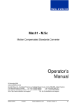
INSTALLATION
MANUAL
SwitchPack 16 Installation Manual - Issue 1, Revision 1, March 2003
© 2003
Snell & Wilcox Post Production Division
The Business and Technology Centre
Shire Hill
SAFFRON WALDEN
Essex, CB11 3AQ
U.K.
Tel:
Fax:
+ 44 (0) 1799 523817
+ 44 (0) 1799 528081
Support Tel:
Support Fax:
Support E-mail:
+ 44 (0) 1799 508100
+ 44 (0) 1799 508800
[email protected]
Web:
http://www.snellwilcox.com
COPYRIGHT
Copyright protection claimed includes all forms and matters of copyrightable material and
information now allowed by statutory or judicial law or hereinafter granted, including without
limitation, material generated from the software programs which are displayed on the screen such
as icons, screen display looks etc.
Information in this manual and software are subject to change without notice and does not
represent a commitment on the part of Snell & Wilcox Ltd. The software described in this manual is
furnished under a license agreement and may not be reproduced or copied in any manner without
prior agreement with Snell & Wilcox Ltd. or their authorised agents.
Reproduction or disassembly of embedded computer programs or algorithms prohibited.
No part of this publication may be transmitted or reproduced in any form or by any means,
electronic or mechanical, including photocopy, recording or any information storage and retrieval
system, without permission being granted, in writing, by the publishers or their authorised agents.
Specification subject to change without notice
All Trademarks acknowledged
ii
SwitchPack 16 Installation Manual - Issue 1, Rev 1
S&W Production Post Production
SAFETY
This symbol refers the user to important information contained in the
accompanying literature. Refer to users manual.
This symbol indicates that hazardous voltages are present inside. There are no
user serviceable parts inside. This unit should only be serviced by trained
personnel.
Servicing instructions, where given, are for use by qualified
personnel only. To reduce risk of electric shock do not
perform any actions on this equipment other than contained
in the operating instructions, unless you are qualified to do
so. Refer all servicing to qualified personnel.
WARNING
TO REDUCE THE RISK OF ELECTRIC SHOCK, DO NOT EXPOSE THIS
APPLIANCE TO RAIN OR MOISTURE.
Always ensure that the unit is properly earthed and power connections correctly made.
This equipment must be supplied from a power system providing a PROTECTIVE EARTH
connection and having a neutral connection which can be reliably identified.
The control panel shall be separately earthed via the terminal on the rear of its enclosure.
The power outlet supplying power to the unit should be close to the unit and easily accessible
Power Supply and Connections
The mainframe and the control panel each have an internal power supply.
Mains Supply Voltage
Before connecting the equipment, observe the safety warnings section and ensure that the local
mains supply is within the rating stated on the rear of the equipment.
Supply voltages for both units must be in the range 100 vac to 120 vac or 200 vac to 240vac
at 50 to 60Hz.
Model Number
PSU Rating
Fuse Rating
Control Panel
4038200
100-120V /
200-240V
1A Max
T1AH
Mainframe
4038550
100-120V /
200-240V
1.75A Max
T2AH
S&W Production Post Production
SwitchPack 16 Installation Manual - Issue 1, Rev 1
iii
Power cable supplied for the USA
The equipment is shipped with a power cord with a standard IEC moulded free socket on one end
and a standard 3-pin plug on the other. If you are required to remove the moulded mains supply
plug, dispose of the plug immediately in a safe manner. The colour code for the lead is as follows:
GREEN lead connected to E
(Protective Earth Conductor)
WHITE lead connected to N
(Neutral Conductor)
BLACK lead connected to L
(Live Conductor)
Power cable supplied for countries other than the USA
The equipment is shipped with a power cable with a standard IEC moulded free socket on one end
and a standard IEC moulded plug on the other. If you are required to remove the moulded mains
supply plug, dispose of the plug immediately in a safe manner. The colour code for the lead is as
follows:
GREEN/YELLOW lead connected to E
(Protective Earth Conductor)
BLUE lead connected to N
(Neutral Conductor)
BROWN lead connected to L
(Live Conductor)
iv
Free Plug
SwitchPack 16 Installation Manual - Issue 1, Rev 1
Free Socket
S&W Production Post Production
Maintenance & Repair
There are no user serviceable parts within either the Mainframe or the Control Panel.
In the unlikely event of an equipment failure contact the Snell & Wilcox Post Production Customer
Support department, contact details below:
Telephone
+ 44 (0) 1799 508100
Fax
+ 44 (0) 1799 508800
e-mail
[email protected]
Cooling Fan Failure
IF A COOLING FAN IN THE MAINFRAME SHOULD STOP FOR ANY REASON THE SYSTEM
SHOULD BE SWITCHED OFF IMMEDIATELY OR PERMANENT DAMAGE MAY RESULT.
Depending on the length of time the mainframe has been run with no fan the unit may need to be
returned for checking and repair. Contact Snell and Wilcox or your Snell and Wilcox dealer to
discuss the situation.
Safety Standards
This equipment complies with the following standards:
BS EN60950 (2000)
Safety of information Technology Equipment Including Electrical Business Equipment.
S&W Production Post Production
SwitchPack 16 Installation Manual - Issue 1, Rev 1
v
EMC Standards
This unit conforms to the following standards:
BS EN 55103-1 : 1997
Electromagnetic Compatibility, Product family standard for audio, video, audio-visual and
entertainment lighting control apparatus for professional use. Part 1. Emission
BS EN 55103-2 : 1997
Electromagnetic Compatibility, Product family standard for audio, video, audio-visual and
entertainment lighting control apparatus for professional use. Part 2. Immunity
Federal Communications Commission Rules Part 15, Class A :1998
EMC Environment
The product(s) described in this manual conform to the EMC requirements for, and are intended for
use in,
either
The commercial and light industrial environment (including, for example, theatres) E2
or
The controlled EMC environment (e.g., purpose-built broadcasting or recording studios), and the
rural outdoor environment (far away from railways, transmitters, overhead power lines, etc.) E4
EMC Performance of Cables and Connectors
Snell & Wilcox products are designed to meet or exceed the requirements of the appropriate
European EMC standards. In order to achieve this performance in real installations it is essential to
use cables and connectors with good EMC characteristics.
All signal connections (including remote control connections) shall be made with screened cables
terminated in connectors having a metal shell. The cable screen shall have a large-area contact
with the metal shell.
COAXIAL CABLES
Coaxial cables connections (particularly serial digital video connections) shall be made with highquality double-screened coaxial cables such as Belden 8281 or BBC type PSF1/2M.
D-TYPE CONNECTORS
D-type connectors shall have metal shells making good RF contact with the cable screen.
Connectors having "dimples", which improve the contact between the plug and socket shells, are
recommended.
vi
SwitchPack 16 Installation Manual - Issue 1, Rev 1
S&W Production Post Production
CONTENTS
Safety ....................................................................................................................….
iii
Unpacking ..................................................................................................................
1
The Mainframe............................................................................................................
1
The Control Panel ......................................................................................................
1
Mainframe Rear View ...............................................................……………………….
2
Port Descriptions ........................................................................................................
2
External Reference Sync ...........................................................................................
2
Updating Software and Hardware ..............................................................................
3
System Info Menu …………………………………………......................................
3
Disk Update Method ...........................................................................................
4
Editor and Panel Cable ………………………………………………………..................
5
Editor Wipe Codes .……………………………………..................................................
6
S&W Production Post Production
SwitchPack 16 Installation Manual - Issue 1, Rev 1
vii
DELIBERATELY BLANK
viii
SwitchPack 16 Installation Manual - Issue 1, Rev 1
S&W Production Post Production
Unpacking
Check the delivery against the shipping note to ensure that all items are present.
Unpack the equipment carefully and check all items for transportation damage. If
damage has occurred contact the shipping company and Snell & Wilcox Ltd or the local
agent immediately with a written description of the visible damage.
The SwitchPack 16 system comes in two boxes, one for the Control panel and the other
for the Switcher Mainframe.
The Control Panel box contains........... Control panel and RS422 Serial Comms cable.
The Mainframe box contains……........ Mainframe and the Manuals.
The Mainframe
The SwitchPack 16 mainframe is designed for mounting in a 19” equipment rack. It
occupies 1 Unit of rack space vertically, and 21 “ ( 535mm) of rack depth.
The mainframe is supplied fitted with two rack mounting “ears”. These ears are
screwed to each side at the front of the mainframe using six Screws, (three each side).
The mainframe should be mounted in a standard 19” rack equipped with a rack tray to
support the weight of the mainframe, using the front ears merely to position it. The ears
should not be used to support the unit.
The Mainframe is cooled by four fans along one side of the unit. These fans draw air in
through vents in the opposite side and the front of the unit providing a cross flow.
Do not obstruct the inlet vents or the fans.
There is no mains power switch on the mainframe.
To the left front of the mainframe is a standard 1.44MB Floppy disc drive for archiving of
all files.
At the rear of the mainframe the mains inlet, video, reference and the control ports are
found.
The external connections are all clearly marked. See diagram of rear panel on page 2.
The Control Panel
The Control Panel is powered from an internal power supply unit.
Communication to the Mainframe is via a RS422 link using 9 pin D Type connectors.
Control Panel operations are described in the user manual.
S&W Production Post Production
SwitchPack 16 Installation Manual - Issue 1, Rev 1
1
Mainframe Rear View
9
10
11
12
13
14
15
16
AUX 1
AUX 2
AUX 3
AUX 4
CLN 3
PS/2
E/NET
INPUTS
1
2
3
4
OUTPUTS
5
6
7
8
BYP
PGM
PST
PANEL
EDIT
SERIAL
SPARE
REF
CLN 1
CLN 2
Port Descriptions
Port Name
Description
Type
PANEL
RS422 serial communications with Control panel
9 Way D-Type
SERIAL
For future use
9 Way D-Type
EDIT
Connection of edit unit
9 Way D-Type
SPARE
Tally/GPI port
15 Way D-type
E/NET
Network Connection
RJ45 Connector
PS/2
PS-2 Mouse port
PC PS-2
IN 1 – 16
Bus Video Sources - Serial Digital Video inputs
Serial BNC
AUX 1 - 4
Auxiliary outputs
Serial BNC
BYP
Outputs program or input 8 on power fail
Serial BNC
PGM
Program Output - Serial Digital Video
Serial BNC
PST
Preset Output - Serial Digital Video
Serial BNC
CLN 1
Program output before all DSK channels
Serial BNC
CLN 2
Program output with DSK channel 1
Serial BNC
CLN 3
Program output with DSK channels 1 and 2
Serial BNC
EXT REF
Black Burst with 300mV Sync (loop)
BNC
External Reference Synchronisation
The SwitchPack 16 MUST be locked to an external analogue reference source, usually
black burst with 300mV sync. The unit auto senses 525/625 signals.
Note.
2
The SwitchPack 16 Engineering - System menu must be set to AUTO for auto sense to
be enabled.
SwitchPack 16 Installation Manual - Issue 1, Rev 1
S&W Production Post Production
UPDATING SOFTWARE AND HARDWARE
System Info Menu
Information about the options installed, the software build date and the hardware build
dates can be accessed from the System Info Menu.
This menu is hidden from normal use. To access it you must press the top three menu
buttons simultaneously (KEY)/ (WIPE 1)/ (WIPE 2).
SD S&W System Info
S/W Build
Panel Ver
Serial No
: 03 Mar 2003
: 2.0
: 00-00-00
Sys Expires
Versn
H/W
: Never
Optns
Figure 1: System Info Menu
The System Info Menu has three sub menus which can be accessed using the bottom
three softkeys {Versn}, {H/W} and {Optns}.
The {Versn} menu (above) displays the mainframe software build date, the panel version
and the serial number.
{H/W} Shows the build date of the hardware system files.
{Optns} Shows the currently active options. These will be either Active or Off
The line “Sys Expires:” Shows the expiry of the main system. If the system expires then
the unit will cease to function. Never means that the system will never expire. “EXPIRED
!!!” means that the system has expired. Contact Snell & Wilcox for an updated Password
Disk. If this line shows a date then the system will expire on that date.
S&W Production Post Production
SwitchPack 16 Installation Manual - Issue 1, Rev 1
3
Disk Update Method
Software, password and hardware updates are mainly provided in the form of one or
more floppy disks. The installation procedure is automated and is carried out as
follows.
Power down the mainframe.
Put the disk in the floppy drive and power up the system.
The machine will now reboot and copy the contents of the floppy disk onto the system
hard drive. The panel will also update to show each file being copied.
When the installation is complete. Remove the disk from the floppy drive and cycle the
power on the mainframe.
The system will now operate as normal again.
4
SwitchPack 16 Installation Manual - Issue 1, Rev 1
S&W Production Post Production
TALLY & GPI INTERFACE
SwitchPack 16 has a simple tally and GPI interface using basic TTL levels.
Tally & GPIs
SwitchPack 16 has 8 tally outputs, corresponding to the video sources one to eight.
The system also has 5 GPI inputs. These can be configured to trigger the AutoTrans,
Cut, Fade to Black transitions and/or Timeline functions.
Electrical Specification
The GPI port is a 15 way Male Connector as shown right.
Pins 1 to 8 correspond to Tally outputs 1 to 8.
11
Pins 9 to 13 correspond to General Purpose Inputs 1 to 5.
Pins 14 & 15 are Signal Ground pins.
5
1
6
10
15
view looking at rear panel
GPIs
All of the input lines are Active Low and are internally pulled up to +5V via 1K2
resistors. GPI inputs are level triggered and are sampled once per field.
Tally Outputs
Tally outputs are Active High TTL signals. These are permanently enabled and require
no software setup. The state of the tally outputs follow the program output bus, as
follows:-
WARNING
Active Button
Tally output
Black
Button 1
Button 2
Button 3
Button 4
Button 5
Button 6
Button 7
Button 8
Matte
All outputs low.
Pin 1 high all others low
Pin 2 high all others low
Pin 3 high all others low
Pin 4 high all others low
Pin 5 high all others low
Pin 6 high all others low
Pin 7 high all others low
Pin 8 high all others low
All outputs low.
THE TALLY AND GPI INTERFACE IS CONNECTED TO THE PROCESSOR
CIRCUITRY.
DAMAGE TO THE PROCESSOR MAY BE CAUSED IF ADEQUATE
PRECAUTIONS ARE NOT TAKEN.
S&W Production Post Production
SwitchPack 16 Installation Manual - Issue 1, Rev 1
5
CONTROL CABLE WIRING
SwitchPack 16 Mainframe to Control Panel or Editor
Panel or Editor
Male 9 Way
D-type
1
1 Tx -
Rx - 2
2 Tx +
Tx + 3
3 Rx +
Gnd 4
4 Rx -
N/C
5
5 Gnd
Gnd 6
6 N/C
Rx + 7
7 N/C
Tx -
8
8 N/C
N/C
9
9 N/C
N/C
6
Mainframe
Female 9 Way
D-type
SwitchPack 16 Installation Manual - Issue 1, Rev 1
S&W Production Post Production
EDITOR WIPE CODES
The following charts describes the wipe codes needed by an editor driving a
SwitchPack 16 switcher. Wipes codes are dependent on the editor protocols selected.
GVG200 Protocol Wipe Codes
200 Wipe Code
0
1
2
3
4
5
6
10
11
12
13
14
17
20
21
22
23
24
30
31
32
33
34
S&W Production Post Production
Function
Vertical Wipe
Top Left Corner Wipe
V Wipe
Circle Wipe
Bottom Left Diagonal Wipe
Clock Wipe
Clock Wipe
Horizontal Wipe
Top Right Corner Wipe
Left V Wipe
Ellipse Wipe
Diagonal Top Left Wipe
45 Cross Wipe
Vertical Mirror Wipe
Bottom Right Corner Wipe
Right V Wipe
Square Wipe
Cross Wipe
Horizontal Mirror Wipe
Bottom Left Corner Wipe
V Bottom Wipe
Diamond Wipe
Egg Timer Wipe
SwitchPack 16 Installation Manual - Issue 1, Rev 1
7
END OF MANUAL
S&W Production Post Production