1
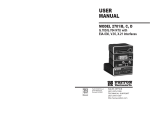
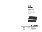
USER
MANUAL
MODEL 1186
Multi-Mode Fiber Modem with
Fixed G.703/G.704 Interface
Part# 07M1186A
Doc# 017161UA
Revised 03/27/00
CERTIFIED
An ISO-9001
Certified
Company
SALES OFFICE
(301)975-1000
TECHNICAL SUPPORT
(301)975-1007
http://www.patton.com
1.0 WARRANTY INFORMATION
TABLE OF CONTENTS
Section
Page
1.0 Warranty Information .............................................................2
1.1 Radio and TV Interference
1.2. CE Notice
1.3 Service
2.0 General Information...............................................................4
2.1 Features
2.2 Description
3.0 Configuration .........................................................................5
3.1 Configure the Hardware DIP Switches
3.1.1 Configuration of the Model 1186
3.1.2 Select RJ-48C or BNC Connector
Patton Electronics warrants all Model 1186 components to be
free from defects, and will—at our option—repair or replace the product should it fail within one year from the first date of shipment.
This warranty is limited to defects in workmanship or materials,
and does not cover customer damage, abuse or unauthorized modification. If this product fails or does not perform as warranted, your sole
recourse shall be repair or replacement as described above. Under no
condition shall Patton Electronics be liable for any damages incurred
by the use of this product. These damages include, but are not limited
to, the following: lost profits, lost savings and incidental or consequential damages arising from the use of or inability to use this product.
Patton Electronics specifically disclaims all other warranties,
expressed or implied, and the installation or use of this product shall
be deemed an acceptance of these terms by the user.
1.1 RADIO AND TV INTERFERENCE
4.0 Installation .............................................................................9
4.1 Connect the G.703/G.704 Network
4.1.1 Connect Twisted Pair to G.703/G.704 Network
4.1.2 Connect Coax Cable to the G.703/G.704 Network
4.2 Connect the Fiber Interface
4.3 Power Connection
4.3.1 Universal AC Power (100-240VAC)
4.3.2 DC Power
Appendix A - Specifications........................................................17
The Model 1186 generates and uses radio frequency energy, and
if not installed and used properly—that is, in strict accordance with the
manufacturer's instructions—may cause interference to radio and television reception. The Model 1186 has been tested and found to comply with the limits for a Class A computing device in accordance with
the specifications in Subpart J of Part 15 of FCC rules, which are
designed to provide reasonable protection from such interference in a
commercial installation. However, there is no guarantee that interference will not occur in a particular installation. If the Model 1186 does
cause interference to radio or television reception, which can be determined by disconnecting the unit, the user is encouraged to try to correct the interference by one or more of the following measures: moving the computing equipment away from the receiver, re-orienting the
receiving antenna and/or plugging the receiving equipment into a different AC outlet (such that the computing equipment and receiver are
on different branches).
Appendix B - Factory Replacement Parts and Accessories.......19
1.2 CE NOTICE
5.0 Operation .............................................................................12
5.1 Power-Up
5.2 LED Status Monitors
5.3 Test Modes
5.3.1 Local Loopback
5.3.2 Remote Digital Loopback
5.3.3 V.52 Test Pattern Generator
The CE symbol on your Patton Electronics equipment indicates
that it is in compliance with the Electromagnetic Compatibility (EMC)
directive and the Low Voltage Directive (LVD) of the European Union
(EU). A Certificate of Compliance is available by contacting Technical
Support.
1
2
2.0 GENERAL INFORMATION
1.3 SERVICE
All warranty and non-warranty repairs must be returned freight
prepaid and insured to Patton Electronics. All returns must have a
Return Materials Authorization number on the outside of the shipping
container. This number may be obtained from Patton Electronics
Technical Service at:
tel:
(301)975-1007
email: [email protected]
www: http://www.patton.com
NOTE:
Packages received without an RMA number will not be
accepted.
Patton Electronics' technical staff is also available to answer any
questions that might arise concerning the installation or use of your
Model 1186. Technical Service hours: 8AM to 5PM EST, Monday
through Friday.
Thank you for your purchase of this Patton Electronics product. This
product has been thoroughly inspected and tested and is warranted for
One Year parts and labor. If any questions or problems arise during installation or use of this product, please do not hesitate to contact Patton
Electronics Technical Support at (301) 975-1007.
2.1 FEATURES
·
·
·
·
·
·
ITU G.703/G.704 (E1) transport over Multi-Mode fiber
Full duplex operation over a single string of fiber
Multi-Mode fiber with max distance 2.5km (1.5 miles)
Two fiber connection options available: ST or SMA
120 Ohm (RJ-48C) and 75 Ohm (dual coax) G.703/G.704 terminations
Clocking Options: Internal, Network (G.703/G.704) or Receive
Recover (fiber link)
· Optional AMI or HDB3 G.703/G.704 data coding
· Six Front Panel LED status indicators: Fiber line, E1 line, LOS, TM,
ER, and NS
· Testing/troubleshooting tools: V.54 compliant local/remote loop
backs, V.52 compliant 511/511E test patterns
2.2 DESCRIPTION
The Patton Electronics Model 1186 offers the ability to extend E1
(G.703/G.704) service over Multi-Mode fiber. A pair of 1186 Multi-Mode
Fiber Modems provides G.703/G.704 Network "extension" between remote
locations (Figure 1).
Fiber Optic Line
G.703/G.704
G.703/G.704
Modem
Modem
Figure 1. Network extension between remote locations
The Model 1186 is designed to transmit/receive G.703/G.704 data
over one string of fiber. The Model 1186 allows transmission over MultiMode fiber with distances up to 2.5 km (1.5 miles). The clocking options
for the Model 1186 include Internal, Network (from G.703/G.704 Network)
or Receive Recovered clock (from fiber line).
The Model 1186 also incorporates V.54 compliant local/remote loopbacks and V.52 compliant 511/511E test patterns. Front panel switches
activate test patterns and loopbacks. LED status indicators monitor the
fiber and G.703/G.704 links. The Model 1186 is available with an AC or
DC power supply and is supported by a wide range of applications and
power supply environments.
3
4
3.0 CONFIGURATION
3.1.1 Configuration of Model 1186
The Model 1186 is equipped with eight DIP switches, which allow
configuration of the unit for a wide variety of applications. This section
describes the switch location and explains all possible configurations.
Switches S1 through S8 may be used to configure clocking modes
and line coding. Default settings of the switches are shown in the table
below. A description of the switch options follows the table.
3.1 CONFIGURE THE HARDWARE DIP SWITCHES
The 8 external dip switches are accessible from the underside of
the Model 1186 (See Figure 2, below).
Front
Rear
Position
Function
Default Setting
S1
S2
S3
S4
S5
S6
S7
S8
Clock Source
Clock Source
Line
Coding
ON
ON
OFF
OFF
Reserved for Future Applications
OFF
} Internal
Clock
}
HDB3
Switches S1 and S2: Clock Mode
Use Switches S1 and S2 to determine clock mode of the 1186.
On
S1
S1
Off
S2
On On
Setting
Internal
Description
Transmit clock generated internally
On Off
Receive Recover Transmit clock derived from the line
Off On
Network
Off Off
Not Used
Transmit clock derived from G.703/G.704
equipment interface
Internal use only
Figure 2. Underside of Model 1186, showing location of the DIP Switches
Figure 3 shows the orientation of the DIP switches in the “ON” and
“OFF” positions.
ON
Note: The Model 1186 units are intended to work in pairs. When setting
the clock modes for the Model 1186 units, one end of the link must be set
for Receive Recover and the other end must be set for either Internal or
Network.
Switch S3 and S4: Line Coding Options
OFF
Figure 3. Close-up of configuration switches
5
Use Switches S3 and S4 to determine whether the G.703/G.704 line
coding is HDB3 or AMI (for older telecommunications equipment). The
line coding must be the same line coding prescribed by the NAP
(Network Access Provider). Most applications will use HDB3.
High Density Bipolar 3 (HDB3): In HDB3 coding, the transmitter
deliberately inserts a bipolar violation when excessive zeros in the
data stream are detected. The receiver recognizes these special vio6
data stream are detected. The receiver recognizes these special
violations and decodes them as zeros. This method enables the
network to meet minimum pulse density requirements. Use HDB3
unless AMI is required in your application.
Alternate Mark Inversion (AMI): AMI defines a pulse as a
“mark,” a binary one, as opposed to a zero. In an E1 Network connection, signals are transmitted as a sequence of ones and zeros.
Ones are sent as pulses, and zeros are sent as spaces, i.e., no
pulse. Every other pulse is inverted from the previous pulse in
polarity, so that the signal can be effectively transmitted. This
means, however, that a long sequence of zeros in the data stream
will cause problems, since the modem receiving the signal relies
on the signal to recover the 2.048 Mbps clock.
Jumper Configuration
The Model 1186 has four internal jumpers: JP2, JP3, JP4 and
JP5. These jumpers are used to match input/output impedance
between the module and external line on the G.703/G.704 Interface.
The jumper settings select either a BNC (75-ohm) or an RJ-48C (120ohm) interface. Figure 4 below shows the top view of the printed circuit
board (PCB) and the location of the jumpers.
If you must use AMI, ensure that the data terminal equipment connected to the unit provides a minimally acceptable pulse density.
For this reason, there are advantages to using HDB3 instead. AMI
coding does not inherently account for ones density. To meet this
requirement, ensure that the data inherently meets pulse density
requirements.
S3
Off
Off
On
On
S4
Off
On
Off
On
DTE Line Coding
HDB3
Internal use only
Internal use only
AMI
Switches S5 through S8: Reserved
Switches S5 through S8 are reserved for future applications and
should be set to OFF.
Figure 4: Top view of 1186 circuit board and location of jumpers
Open the Case
To open the case, insert a screwdriver into the slots and twist the
screwdriver head slightly. The top half of the case will separate from
the lower half of the case. Take caution not to damage any of the PC
board mounted components.
3.1.2 Select RJ-48C or BNC Connectors
Note: Electronic equipment is sensitive to ESD (electrostatic discharge). When you change the internal jumpers on the 1186, use a
grounding strap to avoid damages. For more information call Patton
Technical Support (301) 975-1007.
The Model 1193 is shipped configured for use with a BNC connection to the G.703/G.704 Network. If your Network connection is using
BNC, skip this section.
The following is a description of the jumper settings and the interface
selection:
1. For a 75-ohm connection (BNC/coax), insert all jumpers (default).
2. For a 120-ohm connection (RJ-48C/twisted pair), remove all
jumpers.
7
8
4.0 INSTALLATION
use the diagram below to make the proper connections. The connector pinout and signals are shown in Figure 7, below.
Once the Model 1186 is properly configured, it is ready to connect
to the fiber interface, to the G.703/G.704 equipment, and to the power
source. This section describes how to make these connections.
The power, G.703/G.704 and Fiber Line connections are located
on the rear panel of the Model 1186. Figure 5, below, shows the location of each of these ports.
Network
RX
TX
(Data FROM
G.703/G.704
Network)
(Data TO
G.703/G.704
Network)
Figure 7. Fiber cable to G.703/G.704 Interface connection
4.2 CONNECT THE FIBER INTERFACE
G.703/G.704
Figure 5. G.703/G.704 Interface and power connection ports
4.1 CONNECT THE G.703/G.704 NETWORK
There are two ways to connect to the G.703/G.704 Network. This
section describes both options. After selecting the appropriate connection, set the internal jumpers as described in section 3.1.2 of this manual.
The Model 1186 is designed to be connected to another Model
1186. The Model 1186 supports communication between G.703/G.704
equipment over one string of multi-mode fiber at distances up to 2.5
km (1.5 miles). One modem can connect to another on the end of a
single string of fiber optic cable.
To connect two Model 1186s, use one string of 62.5/125 micron
multi-mode fiber. The fiber connects to each Model 1186 using either
an ST or an SMA connector.
Figure 8 below shows a close-up of both connector types.
4.1.1 Connect Twisted Pair (120 Ohm) to G.703/G.704 Network
The Model 1186 is equipped with a single RJ-48C jack option for
connections to a G.703/G.704 Network. If your G.703/G.704 Network
terminates via an RJ-48C, use the diagram below (Figure 6).
1
2
3
4
5
6
7
8
1
2
3
4
5
6
7
8
RX Data (TIP)
RX Data (RING)
(no connection)
TX Data (TIP)
TX Data (RING)
(no connection)
(no connection)
(no connection)
}
From Network
}
To Network
Figure 8: Model 1186 SMA and ST multi-mode fiber connectors
Figure 6. G.703/G.704 Network Interface.
4.1.2 Connect Coax Cable to the G.703/G.704 Network
The Model 1186 is also equipped with dual female BNCs (TX and
RX) for connection to a 75 ohm dual coax G.703/G.704 Network interface. If your G.703/G.704 Network terminates via dual coaxial cable,
9
10
5.0 OPERATION
4.3 POWER CONNECTION
4.3.1 Universal AC Power (100-240VAC)
The Model 1186 uses a 5VDC, 2A universal input 100-240VAC,
power supply (center pin is +5V). The universal input power supply
has a male IEC-320 power entry connector. This power supply connects to the Model 1186 by means of a barrel jack on the rear panel.
Many international power cords are available for the universal power
supply (Please refer to Appendix B for country-specific power cords).
The Model 1186 powers up as soon as it is plugged into an AC
outlet. The unit does not have a power switch.
4.3.2 DC Power
The 36-60 VDC DC to DC adapter supplied with the DC version of
the Model 1186 plugs in a DC source (nominal 48VDC) and plugs into
the barrel power supply jack on the rear of the 1186. Please refer to
Figure 9 to make the proper connection.
Once the Model 1186 is properly configured and installed, it should
operate transparently. This sections describes power-up, reading the
LED status monitors, and using the built-in loopback test modes.
5.1 POWER-UP
To apply power to the Model 1186, first be sure that you have read
Section 4.3, and that the unit is connected to the appropriate power
source.
Next, make sure that front panel switches are set to Normal condition. Then, plug provided power adapter (see section 4.3) first into the
rear panel outlet of the Model 1186, and then into the acceptable power
outlet (AC or DC depending on the model -UI or -DC). After both the
local and remote Model 1186s are powered up, a synchronization
process will occur to establish a link. The synchronization process
should take only a few seconds (<5 sec). Any time one of the Models
1186 loses power (i.e., in a lightning storm), the local and remote units
will re-synchronize before they can resume data transmission.
When the local and remote units have established a link and are
passing reliable data, the following LED conditions will exsit:
To -48VDC
Source
-Vin
To Power
Supply Jack
+Vin
·
·
·
·
·
·
Fiber
E1
LOS
NS
ER
TM
=
=
=
=
=
=
GREEN
GREEN
OFF
OFF
OFF
OFF
Figure 9. Connect DC power to the 48V-PSM DC power supply
5.2 LED STATUS MONITORS
WARNING!
There are no user-serviceable parts in the
power supply section of the Model 1186. Fuse replacement
should only be performed by qualified service personnel.
Contact Patton Electronics Technical Support at (301) 9751007, via our web site at http://www.patton.com, or by e-mail
at [email protected], for more information.
The Model 1186 features six front panel status LEDs that indicate
the condition of the modem and communication link. Figure 10 shows
the front panel location of each LED.
Multi-Mode Fiber G.703/G.704 Modem
Figure 10. Model 1186 front panel
11
12
Functions of LEDs are as follows:
5.3 TEST MODES
Fiber
The green Fiber LED indicates reliable data on the fiber side
E1
The green E1 LED indicates reliable data on the G.703/G.704
side
The following section describes the test patterns and loopbacks
used in the Model 1186. The Model 1186 offers V.54 compliant
local/remote loopback tests, plus a built-in V.52 BER test pattern generator to evaluate the condition of the modems and the communication
link. These tests can be activated physically from the front panel.
LOS
The red LOS indicates that syncronization between modems
has not been established. Blinking red LOS LED indicates the
presense of coding errors
NS
The red NS LED indicates that the signal on the fiber side is
too weak to be detected, which can be due to any of the following reasons:
- break in the fiber optic cable
- length of the fiber optic cable exceeds the maximum distance
- problem with Fiber LED.
ER
Flashing red ER LED indicates errors in 511 test pattern
TM
The yellow TM LED indicates that modem is in a test mode
(Local/Remote Loopback or 511/511E test pattern). Opaque
TM indicates normal operation.
5.3.1 Local Loopback
The local loopback test checks the operation of the local Model
1186, and is performed separately on each unit. The following section
describes how to perform a local loopback test between the Network
and a local connection.
Any data sent to the local Model 1186 in this test mode will be echoed
(returned) back to the user (see Figure 11). If two Model 1186 units are
linked when the LAL is activated, data sent from the remote modem will
also be looped back to the remote terminal equipment.
G.703/G.704
Network
Figure 11. Local Loopback Diagram
To test the local connection, follow these steps:
1. Activate LAL by moving the front panel toggle switch UP to "Local".
Once the Local Loopback is activated, the Model 1186 transmit output
will be connected to its own receiver. The TM LED will light up.
2. Perform a BER (Bit Error Rate) test on each unit using a separate
BER tester. If the BER test equipment indicates no faults, but the data
indicates a fault, follow the manufacturer's checkout procedures for the
data terminal. Also, check the interface cable between the terminal and
the Model 1186. The BER test can also be performed using a built-in
511/511E pattern generator. (See section 5.3.3 on how to use the built-in
511/511E pattern generator.)
3. Upon completion of the LAL test, return the front panel switch to the
NORMAL position. The TM LED should turn off.
13
14
5.3.2. Remote Digital Loopback (RDL)
The Remote Digital Loopback test checks the performance of both
the local and remote Model 1186s, and the communication link
between them. In this test, any characters sent from the originating
device to the remote unit will be returned (see Figure 12). Any data
sent from the remote DTE wil be ignored.
2. If the above test indicates no errors, move the V.52 toggle switch
DOWN, activating the "511/E" test with errors present. If the test is
working properly, the local modem's red "ER" LED will blink once every
two seconds. A successful "511/E" test will confirm that the link is in
place, and that the built-in "511" generator and detector are working
properly.
Note: When the unit is set for Network Clock Mode, the unit will
derivew its timing from the G.703/G.704 Interface. Failure to connect
to G.703/G.704 may result in bit errors during the 511 or 511/E test.
G.703/G.704
Network
Figure 12. Remote Loopback Diagram
To perform a RDL test, follow these steps:
1. Activate RDL by moving front panel toggle switch DOWN to
"Remote". The TM LED on both local and remote units will light up.
2. Perform a BER (Bit Error Rate) test on the system, using BER tester
on the local end. BER test can also be performed using built-in
511/511E pattern generator. (See section 5.3.3 on how to use the builtin 511/511E pattern generator.)
3. If the BER test equipment indicates a fault and the Local Analog
Loopback test was successful for both Model 1186s, there may be a
problem with the line between the units.
4. Upon completion of the RDL test, return the front panel switch to
the NORMAL position. The TM LED should turn off on both local and
remote units.
5.3.3. V.52 Test Pattern Generator
To use the V.52 BER test in conjunction with the Local or Remote
Loopbacks, follow these instructions:
1. Locate the "511/511E" toggle switch on the front panel of the Model
1186 and move it UP. This activates the V.52 BER test mode and
transmits a "511" test pattern into the loop. If any errors are present,
the local modem's red "ER" LED will blink intermittently.
15
16
APPENDIX A
PATTON ELECTRONICS MULTI-MODE FIBER MODEM WITH
G.703/G.704 INTERFACE
SPECIFICATIONS
Clocking Modes:
Line Rate:
Diagnostics:
LED Status:
Configuration:
Power:
Compliance:
Transmission Line:
Line Coding:
Line Interface:
Fiber Physical
Connection:
Network (G.703/G.704), Internal, Receive
Recover
2048 kbps
V.52 compliant (511/511E) pattern generator
and detector with error injection mode.
Remote Loopback (toward fiber line) and
local loopback (toward G.703/G.704 network) controlled by a single front panel
switch
The following LEDs are displayed on the
front panel:
Fiber: The green Fiber LED indicates reliable data on the fiber side
E1: The green E1 LED indicates reliable
data on the G.703/G.704 side
LOS: The red LOS indicates that syncronization between modems has not been
established. Blinking red LOS LED indicates
the presense of coding errors
NS: The red NS LED indicates that the sig
nal on the fiber side is too weak to be
detected
ER: Flashing red ER LED indicates errors in
511 test pattern
TM: The yellow TM LED indicates that
modem is in a test mode
(Local/Remote Loopback or 511/511E test
pattern). Opaque TM LED indicates normal
operation.
Externally accessible dip switches
5 VDC from external desk top power supply,
90-260VAC, 50-60 Hz (Universal
Input), 10W or -48 VDC
FCC Part 15, CE, CTR12
Single fiber
8B10B
Transformer coupled, 1500 VAC isolation
G.703/G.704 Specific
Interface:
Line rate:
Line coding:
Isolation:
Physical Connection:
Female Dual Coaxial 75 ohm or
Female RJ-48C 120 ohm
2.048 Mbps
AMI or HDB3 (HDB3 is the default)
1500 Vrms
pin 1 Rx Data +
pin 2 Rx Data pin 4 Tx Data pin 5 Tx Data pins 3, 6, 7, 8 no connection
One string of 62.5 M25 mm fiber with SMA
or ST connectors
17
18
APPENDIX B
PATTON ELECTRONICS MODEL 1186
FACTORY REPLACEMENT PARTS
AND ACCESSORIES
Patton Electronics Model #
Description
1186 ................................multi-mode fiber optic modem
1186RC............................multi-mode fiber rack card modem
48V-PSM.........................DC Power Supply Module
08055DCUI .....................100-240VAC (+5V ±5% reg. DC/2A)
Universal Input Adapter
0805EUR ........................European Power Cord CEE 7 (“A”)
0805UK ...........................United Kingdom Power Cord (“D”)
0805US ...........................American Power Cord (“K”)
0805AUS .........................Australia/New Zealand Power Cord (“C”)
0805DEN.........................Denmark Power Cord (“E”)
0805FR............................France/Belgium Power Cord (“F”)
0805IN.............................India Power Cord (“G”)
0805IS .............................Israel Power Cord (“H”)
0805JAP..........................Japan Power Cord (“J”)
0805SW...........................Switzerland Power Cord (“L”)
07M1186..........................User Manual
Copyright ©2000
Patton Electronics Company
All Rights Reserved
19