1
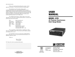
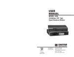
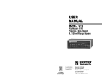
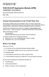
USER
MANUAL
MODEL 2450
56/64 Kbps, 4-Wire
DDS & Clear Channel
CSU/DSU
Part# 07M2450-B
Doc# 099051UB
Revised 3/12/97
CERTIFIED
An ISO-9001
Certified Company
SALES OFFICE
(301) 975-1000
TECHNICAL SUPPORT
(301) 975-1007
http://www.patton.com
1.0 WARRANTY INFORMATION
Patton Electronics warrants all Model 2450 components to be
free from defects, and will—at our option—repair or replace the product
should it fail within one year from the first date of shipment.
This warranty is limited to defects in workmanship or materials, and
does not cover customer damage, abuse or unauthorized modification.
If this product fails or does not perform as warranted, your sole
recourse shall be repair or replacement as described above. Under no
condition shall Patton Electronics be liable for any damages incurred
by the use of this product. These damages include, but are not limited
to, the following: lost profits, lost savings and incidental or
consequential damages arising from the use of or inability to use this
product. Patton Electronics specifically disclaims all other warranties,
expressed or implied, and the installation or use of this product shall be
deemed an acceptance of these terms by the user.
1.1 RADIO AND TV INTERFERENCE
The Model 2450 generates and uses radio frequency energy, and if
not installed and used properly—that is, in strict accordance with the
manufacturer's instructions—may cause interference to radio and
television reception. The Model 2450 has been tested and found to
comply with the limits for a Class A computing device in accordance
with the specifications in Subpart J of Part 15 of FCC rules, which are
designed to provide reasonable protection from such interference in a
commercial installation. However, there is no guarantee that
interference will not occur in a particular installation. If the Model 2450
does cause interference to radio or television reception, which can be
determined by disconnecting the RS-232 interface, the user is
encouraged to try to correct the interference by one or more of the
following measures: moving the computing equipment away from the
receiver, re-orienting the receiving antenna and/or plugging the
receiving equipment into a different AC outlet (such that the computing
equipment and receiver are on different branches). In the event the
user detects intermittent or continuous product malfunction due to
nearby high power transmitting radio frequency equipment, the user is
strongly advised to use data cables with an exterior outer shield bonded
to a metal or metalized connector
1.2 FCC INFORMATION
Your telephone company may make changes in its facilities,
equipment, operations or procedures that could affect the proper
operation of the Model 2450 Series. If this happens, the telephone
company should give you advance notice to prevent the interruption of
your service.
The telephone company may decide to temporarily discontinue
your service if they believe your Model 2450 Series may cause harm to
the telephone network. Whenever possible, they will contact you in
advance. If you elect to do so, you have the right to file a complaint
with the FCC. The telephone company may ask you to disconnect the
equipment from the telephone network until the problem has been
corrected or until you are certain that the Model 2400 Series is not
malfunctioning.
The following information may be required when applying to your
local telephone company for leased line facilities.
Service
Type
56 Kbps
64 Kbps
Digital Facility
Interface Code
04 DU5 - 56
04 DU5 - 64
Service Order
Code
6.0F
6.0F
1.3 SERVICE INFORMATION
All warranty and non-warranty repairs must be returned freight
prepaid and insured to Patton Electronics. All returns must have a
Return Materials Authorization number on the outside of the shipping
container. This number may be obtained from Patton Electronics
Technical Support: (301) 975-1007; http://www.patton.com; or,
[email protected]. Notice: Packages received without an RMA
number will not be accepted. Patton Electronics' technical staff is also
available to answer any questions that might arise concerning the
installation or use of your Model 2400. Technical Service hours: 8AM
to 5PM EST, Monday through Friday.
1.4 CE NOTICE
The CE symbol on your Patton Electronics equipment indicates
that it is in compliance with the Electromagnetic Compatibility (EMC)
directive and the Low Voltage Directive (LVD) of the Union European
(EU). A Certificate of Compliance is available by contacting Patton
Technical Support.
The Model 2400 Series has been tested and registered in
compliance with the specifications in Part 68 of the FCC rules. A label
on the equipment bears the FCC registration number. You may be
requested to provide this information to your telephone company.
1
Network
Jacks
RJ48S
RJ48S
2
3.0 CONFIGURATION
2.0 GENERAL INFORMATION
Thank you for your purchase of this Patton Electronics product.
This product has been thoroughly inspected by Patton's qualified
technicians. If any questions or problems arise during installation or
use of this product, please do not hesitate to contact Patton Electronics
Technical Support at (301) 975-1007.
2.1 FEATURES
•
•
•
•
•
•
•
•
•
•
•
•
•
Synchronous data rates of 56 or 64 Kbps
Full duplex communication over two dedicated twisted pairs
Supports distances to 3.4 miles over 26 AWG wire
Selectable internal, external or network rcv/recover clock options
Built-in V.54 loopback tests and V.52 BER test patterns
Works with 56 Kbps DDS, 64 Kbps Clear Channel, or private
twisted pair circuits
Switchable Circuit Assurance feature
Externally accessible configuration switches
Six front panel LEDs monitor communication and test status
RJ-48S jack provided for line connection
RS-232 & RS-422/530 versions have DB-25 connector
V.35 version has either DB-25 or M/34 connector
Ultra-compact enclosure fits in tight spaces
The Model 2450 is easy to install and is ruggedly designed for
excellent reliability: just set it and forget it. The following instructions
will help you set up and install the Model 2450 properly.
3.1 CONFIGURATION SWITCHES
The Model 2450 uses a mini DIP switch package that allows
configuration to a wide range of applications. This DIP switch is
externally accessible from the underside of the Model 2450 (see Figure
1, below), therefore you do not need to open the Model 2450's case
during configuration.
REAR
ON
1
2
3
4
5
6
7
8
S1
FRONT
Figure 1. Underside of Model 2450, showing location of DIP switches
2.2 DESCRIPTION
3.2 CONFIGURATION SWITCH SET “S1”
The Model 2450 DDS & Clear Channel CSU/DSU is a standalone ,
AC powered CSU/DSU designed for 4-wire, full duplex communications
over dedicated twisted-pair. Synchronous data rates of 56 and 64 Kbps
are supported, at distances up to 3.4 miles. The Model 2450 provides
selectable timing options of internal, external or network receiverecovered clock. A circuit assurance feature is also provided.
For user convenience, the Model 2450’s DIP switches are
externally accessible, so there is no need to open the case to configure
the unit. The Model 2450’s built-in V.54 loopback test modes and V.52
BER test patterns are accessed using two front panel switches. Six
front panel LEDs monitor test modes and communication status. Line
connections are facilitated by a modular RJ-48S jack on the rear of the
unit.
The switches shown in Figure 2 below and on DIP switch S1 control
clock mode, circuit assurance, RTS, data rate and test loop functions.
Following Figure 2 are factory default settings and detailed switch
descriptions for each switch.
3
4
ON
ON
1
2
3
4
5
6
7
8
OFF
Figure 2. Close-up of DIP switches showing “ON” and “OFF” positions
Switch S1-3: Circuit Assurance
S1 SUMMARY TABLE
Position
Function
Factory Default
S1-1
Clock Mode
Off
S1-2
Clock Mode
On
S1-3
Circuit Assurance
Off
Disabled
S1-4
RTS
On
Forced On
S1-5
Line Rate
Off
56 kbps
S1-6
Front Panel Switches
Off
Enabled
S1-7
DTE Loop Control
On
Disabled
S1-8
Receive RDL
Off
Enabled
}
Network
On dedicated circuits, the transmitter and the CTS output can be
configured to go On only when a working communication circuit is
established. If Circuit Assurance is used, enable it on only one end of
the communication link.
S1-3
On
Circuit
Assurance
Enabled
Off
Disabled
Switches S1-1 and S1-2: Clock Mode
The setting for switches S1-1 and S1-2 determines the transmitter
clocking mode for the Model 2450.
S1-1
S1-2
Clock Mode
Description
On
Off
External (DTE)
Transmit clock derived
from terminal interface
Off
On
Network (Looped)
Transmit clock derived
from the received line
signal; Use this mode
for Dedicated DDS
operation
Off
Off
Internal (Master)
Transmit clock derived
internally
On
On
Campus Clock
Transmit clock derived
from received line
signal. Allows remote
device (in campus
clock mode) to initiate
V.54 loopback. For use
only in campus shorthaul configuration.
(Note: Local device
must be in internal
clock mode.)
5
Description
CTS will go low and the
transmitter will be held off if the
receiver is in the No Signal state
or CD is low
The transmitter and CTS will
operate without regard to the
receiver state
Switch S1-4: RTS
The RTS input can be forced on, ignoring the terminal’s RTS
signal. RTS controls the transmitter by either sending the user’s data
or sending an idle code.
S1-4
On
RTS
Forced On
Description
Transmitter is always ON
Off
Follows
DTE Signal
The RTS input controls the
transmitter
Switches S1-5: Data Rate
This switch controls the data rate on the line (RJ-48S port) and
must match the speed of your digital service.
S1-5
Off
Setting
56 kbps
On
64 kbps
6
4.0 INSTALLATION
Switch S1-6: Front Panel Switch Enable/Disable
Switch S1-6 determines whether the front panel switches may be
used to perform diagnostic functions.
S1-6
Off
On
Activation
Enabled
Disabled
Description
Front panel switches may be used
to activate/terminate diagnostics
Front panel switches will have no
effect on operation of the unit
Switch S1-7: DTE Loop Request Line Enable/Disable
The setting for switch S1-7 determines whether the DTE signals
can be used to activate/terminate the loopback diagnostic modes and
BER test patterns.
S1-7
Off
DTE TM Line
Activation
Enabled
On
Disabled
The Model 2450 is designed for 4-wire, full duplex communication
over a DDS or Clear Channel carrier circuit, or over dedicated twisted
pair. This section will describe proper connection of the line interface,
the DTE (terminal) interface, and the AC power supply.
4.1 LINE (NETWORK) CONNECTION
The RJ-48S port on a Model 2450 CSU/DSU is prewired for a
standard TELCO wiring environment (see Figure 4, below). Connect
this port to the RJ-48S jack provided by your digital service carrier
using a straight through twisted pair cable between 19 and 26 AWG.
To be sure you have the right wiring, use the table below as a guide.
1
2
3
4
5
6
7
8
Description
DTE Loop request line switches
may be used to activate/terminate
diagnostics.
DTE loop request lines will
have no effect on operation of
the unit.
1 (TX+)
2 (TX-)
3 (N/C)
4 (N/C)
5 (N/C)
6 (N/C)
7 (RX+)
8 (RX-)
Figure 4. Interface pinouts for Model 2450 RJ-48S jack.
4.1.1 CONNECTING OVER PRIVATE TWISTED PAIR
Switch S1-8: Receive RDL Enable/Disable
Switch S1-8 determines whether or not the unit will respond to loop
requests from the remote device.
S1-6
Off
Activation
Enabled
Description
Unit wil respond to loop requests
from the remote device.
On
Disabled
Unit wil ignore loop requests from
the remote device.
7
If you are using a pair of Model 2450s as short range modems over
private twisted pair, make the connection between them using a twisted
pair crossover cable pinned according to the diagram below.
RJ-48S Cable (4-Wire)
SIGNAL
PIN#
PIN#
TX+
TXRX+
RX-
1-----------------------7
2-----------------------8
7-----------------------1
8-----------------------2
8
SIGNAL
RX+
RXTX+
TX-
5.0 OPERATION
4.2 DTE (TERMINAL) CONNECTION
The Model 2450 is wired to connect to a DTE. If your terminal
device is DCE, call Patton Technical Support at (301) 975-1007 for
specific installation instructions.
Four versions of the Model 2450 are available, with respect to DTE
interface and connector type (see Appendix C). All versions connect to
the DTE using a straight through cable. When constructing or
purchasing your interface cable, refer to the pinout diagrams in
Appendix D.
4.3 AC POWER CONNECTION
Once you have configured the Model 2450 properly (see Section
3.0) and made line, DTE and power connections correctly (see Section
4.0), you are ready to operate the unit(s). (Note: the unit is operational
as soon as power is applied–there is no power switch.) This section
describes the LED status monitors, and use of the built-in V.54 and V.52
test modes.
5.1 LED STATUS MONITORS
The Model 2450 features six front panel status LEDs that indicate
the condition of the unit and communication link. Figure 6 (below)
shows the front panel location of each LED. Following Figure 6 is a
description of each LED's function.
Power is supplied to the Model 2450 by a 10 VAC, 1 A wall mount
transformer. This transformer connects to the Model 2450 by means of
a cannon jack on the rear panel. The Model 2450 is powered-up as
soon as it is plugged into an AC outlet–there is no power switch.
Model 2450 MiniLink-I 56/64 CSU/DSU
TD
RD
CD
Error
NS
V.54 Test
Modes
Test
4.3.1 120 VAC Power (US)
511
511E
The 120 VAC adapter supplied with the standard version of the
Model 2450 is a “wall mount” type, and may be plugged into any
approved 120 VAC wall plug.
4.3.2 230 VAC Power (IEC)
The 230 VAC adapter supplied with the “international” version of the
Model 2450 is equipped with an IEC-320 shrouded male connector.
This connects with one of several available country-specific power
cords (see the ordering information in Appendix C). You may
purchase these power cords from Patton Electronics, or from a local
vendor of your choice.
9
Remote
Normal
Local
Figure 6. Front view of Model 2450
•
“TD” (Transmit Data) glows red to indicate an Idle condition or
Binary “1” data. Green indicates Binary “0” data.
•
“RD” (Receive Data) glows red to indicate an Idle condition or
Binary “1” data. Green indicates Binary “0” data.
•
“CD” (Carrier Detect) glows green when carrier is active. In 64
Kbps mode, CD glows red if there is no carrier, or if a bipolar
violation occurs. In 56 Kbps mode, CD glows red if there is no
carrier, if an Out-of-Service or Out-of-Frame violation occurs,
or if idle code is detected.
•
“NS” (No Signal) glows red when there is no valid carrier. This
means the Model 2450 receiver has not detected a valid signal
from the digital service provider, or, in the case of short-haul
operation, from the remote Model 2540. If NS is lit, check for
an unplugged cable, broken wire or an incorrect Line Rate
selection.
10
•
•
“Error” glows red when errors are detected in test mode during
the “511” and 511/E” tests. This indicator also glows during
normal operation to indicated framing errors and/or bipolar
violations in 64 Kbps mode, or invalid bipolar violations in 56
Kbps mode (see Figure 7, below).
“Test” glows red when the V.54 loopback tests or V.52 BER
tests are initiated.
5.2 TEST MODES
The Model 2450 offers two V.54 test modes, plus a built-in V.52
BER test pattern generator, to evaluate the condition of the modems
and the communication link. These tests can be activated physically
from the front panel, or via the interface.
5.2.1 Using Local Analog Loopback (LAL)
The Local Analog Loopback (LAL) test checks the operation of the
local Model 2450, and is performed separately on each unit. Any data
sent to the local Model 2450 in this test mode will be echoed (returned)
back to the user device. For example, characters typed on the
keyboard of a terminal will appear on the terminal screen. To perform a
LAL test, follow these steps:
1. Activate LAL. This may be done in one of two ways: First, by
moving the front panel toggle switch DOWN to “Local”, and; second, by
raising pin 18 on the interface. (Note: Make sure DIP switch S1-7 is
OFF). Once LAL is activated, the Model 2450 transmitter output is
connected to its own receiver. The “Test” LED should be lit.
2. Verify that the data terminal equipment is operating properly
and can be used for a test. If a fault is indicated, call a technician or
replace the unit.
3. Perform a V.52 BER (bit error rate) test as described in Section
5.2.3. If the BER test equipment indicates no faults, but the data
terminal indicates a fault, follow the manufacturer’s checkout
procedures for the data terminal. Also, check the interface cable
between the terminal and the Model 2450.
11
5.2.2 Using Remote Digital Loopback (RDL)
The Remote Digital Loopback (RDL) test checks the performance
of both the local and remote Model 2450s, and the communication link
between them. Any characters sent to the remote Model 2450 in this
test mode will be returned back to the originating device. For example,
characters typed on the keyboard of the local terminal will appear on
the local terminal screen after having been passed to the remote Model
2450 and looped back. To perform an RDL test, follow these steps:
1. Activate RDL. This may be done in two ways: First, by moving
the front panel toggle switch UP to “Remote”, and; second, by raising
pin 21 on the interface. (Note: Make sure S1-7 is OFF).
2. Perform a V.52 BER test as described in Section 5.2.3. If the
BER test equipment indicates a fault, and the Local Analog Loopback
test was successful for both Model 2450s, you may have a problem
with the twisted pair line between the modems. You should then check
the twisted pair line for proper connections and continuity.
5.2.3 Using the V.52 BER Test
To use the V.52 BER tests in conjunction with the V.54 loopback
tests, follow these instructions:
1. Locate the “511/511E” toggle switch on the front panel of the
2450 and move it UP. This activates the V.52 BER test mode and
transmits a “511” pseudo-rando test pattern into the loop. If any errors
are present, the local modem’s red “Error” LED will blink sporadically.
2. If the above test indicates no errors are present, move the V.52
toggle switch DOWN, activating the “511/E” test with errors present. If
the test is working properly, the local modem's red “Error” LED will glow.
A successful “511/E” test will confirm that the link is in place, and that
the Model 2450’s built-in “511” generator and detector are working
properly.
Note: The above V.52 BER tests can be used independently of the
V.54 loopback tests. This requires two operators: one to initiate and
monitor the tests at the local Model 2450, and one to do the same at
the remote Model 2450. In this case, the test pattern sent by each
Model 2450 will not be looped back, but will be transmitted down the
line to the other Model 2450. Both operators must initiate and monitor
the tests simultaneously.
12
APPENDIX A
APPENDIX B
CABLE RECOMMENDATIONS
PATTON MODEL 2450 SPECIFICATIONS
DDS Type:
Transmission Format:
Maximum Operating
Distance:
DTE Interface:
DDS Line Interface:
Standards:
DDS Line Rates:
DTE Rates:
Transmission Line:
Applications:
Indicators:
Diagnostics:
Power Supply:
Dimensions:
Dedicated
Synchronous, full duplex
18000 feet (3.4 miles) over 26 AWG twisted
pair
RS-232 (DB-25 female), RS-422/530 (DB25 female), V.35 (M/34 female or DB-25
female)
RJ-48S jack
AT&T 62310 compliant
56 and 64 Kbps
56 and 64 Kbps
4-wire
DDS, point-to-point or multipoint; Clear
Channel, point-to-point; campus-area pointto-point
LED indicators for TD, RD, CD, No Signal,
Error and Test Mode
V.54 compliant local and remote loopback
tests; V.52 compliant 511/511E BER test
120 VAC, 60 Hz or 230 VAC, 50 Hz to 10
VAC, 1A wall mount transformer
(RS-232 version) 1.65”H x 4.18”W x 3.55”D;
(V.35 version w/ screws) 1.65”H x 4.18”W x
3.96”D
The following statements apply to the Model 2450 when used as a
short range modem over private twisted pair:
All Patton Electronics Company Short Range Modems (SRMs) are
tested to the distances published in our Catalogs and Specification
Sheets on twisted-pair cable with the following characteristics:
Wire Gauge
Capacitance
Resistance
19 AWG
22 AWG
24 AWG
26 AWG
83nF/mi or 15.72 pF/ft.
83nF/mi or 15.72 pF/ft.
83nF/mi or 15.72 pF/ft.
83nF/mi or 15.72 pF/ft.
.0163Ω/ft.
.0326Ω/ft.
.05165Ω/ft.
.08235Ω/ft.
We fully expect that the Short Range Modems will operate on lines
with specifications different from those tested, but to reduce the
potential difficulties in the field, one should ensure that the cable being
used has similar or better characteristics (lower capacitance or lower
resistance).
Wire with capacitance of 20pF/ft. or less is suitable for all our Short
Range Modems . However, distances may vary from those published in
our catalog. Variations in wire resistance will also affect distance but
not functionality. Wire should be 26 AWG or larger (smaller AWG#).
Patton products are designed to withstand normal environmental
noise and conditions however, other environmental factors too
numerous to discuss in this format may affect proper operation of the
SRM’s.
Selection of the proper SRM for an application is critical to
maintaining Customer Satisfaction and should be taken seriously.
Certain models are better suited for particular applications and
environments than others.
13
14
APPENDIX D
INTERFACE PIN ASSIGNMENT
APPENDIX C
FACTORY REPLACEMENT PARTS
AND ACCESSORIES
DDS/CLEAR CHANNEL INTERFACE
Patton Model #
Description
The DDS/Clear Channel Interface is an RJ-48S modular jack.
2450/A .............................56/64 kbps CSU/DSU (RS-232. DB-25
female connector)
2450/B .............................56/64 kbps CSU/DSU (RS-422/530,
DB-25 female connector)
2450/C.............................56/64 kbps CSU/DSU (V.35, M/34
female connector)
2450/E .............................56/64 kbps CSU/DSU (V.35, DB-25
female connector)
10-2500 ...........................DDS Cable, RJ48S - RJ48S, 6 foot
080510 ACB ....................120V Wall Mount AC Adapter
080512 ACIB ...................230V AC adapter (No Power Cord)
0805US ...........................American Power Cord
0805EUR.........................European Power Cord CEE 7
0805EURP ......................Europlug Power Cord CEE 7/16
0805UK ...........................United Kingdom Power Cord
0805AUS .........................Australia/New Zealand Power Cord
0805DEN.........................Denmark Power Cord
0805FR............................France/Belgium Power Cord
0805IN.............................India Power Cord
0805IS .............................Israel Power Cord
0805JAP..........................Japan Power Cord
0805SW...........................Switzerland Power Cord
15
Pin #
1
2
3
4
5
6
7
8
Signal
TX+
TXno connection
no connection
no connection
no connection
RX+
RX-
MODEL 2450/C
M/34 CONNECTOR (V.35), TERMINAL INTERFACE
Pin #
A
B
C
D
E
F
L
M
N
P
R
S
T
U
V
W
X
Y
AA
Signal
Frame Ground
SGND (Signal Ground)
RTS
CTS
DSR
CD
LL (Local Loop)
TM (Test Mode)
RL (Remote Loop)
TD
RD
TD/
RD/
XTC
RC
XTC/
RC/
TC
TC/
16
(APPENDIX D - Continued)
(APPENDIX D - Continued)
MODEL 2450/A
DB-25 CONNECTOR (RS-232/V.24), TERMINAL INTERFACE
MODEL 2450/E
DB-25 CONNECTOR (V.35), TERMINAL INTERFACE
Pin #
1
2
3
4
5
6
7
8
15
17
18
21
24
25
Signal
Frame Ground
TD
RD
RTS
CTS
DSR
SGND (Signal Ground)
CD
TC
RC
LL (Local Loop)
RL (Remote Loop)
XTC
TM (Test Mode)
MODEL 2450/B
DB-25 CONNECTOR (RS-422/530), TERMINAL INTERFACE
Pin #
1
2
3
4
5
6
7
8
9
11
12
14
15
16
17
18
21
24
25
Signal
Frame Ground
Transmit Data A
Receive Data A
RTS
CTS
DSR
SGND (Signal Ground)
CD
Receive Clock B
External Clock B
Transmit Clock B
Transmit Data B
Transmit Clock A
Recieve Data B
Receive Clock A
LL (Local Loop)
RL (Remote Loop)
External Clock A
TM (Test Mode)
17
Pin #
1
2
3
4
5
6
7
8
9
11
12
14
15
16
17
18
21
24
25
Signal
Frame Ground
Transmit Data A
Receive Data A
RTS
CTS
DSR
SGND (Signal Ground)
CD
Receive Clock B
External Clock B
Transmit Clock B
Transmit Data B
Transmit Clock A
Recieve Data B
Receive Clock A
LL (Local Loop)
RL (Remote Loop)
External Clock A
TM (Test Mode)
Copyright ©
Patton Electronics Company
All Rights Reserved
18
Dear Valued Customer,
Thank you for purchasing Patton Electronics products! We do
appreciate your business. I trust that you find this user manual helpful.
We manufacture one of the widest selections of data communications
products in the world including CSU/DSU's, network termination units,
powered and self-powered short range modems, fiber optic modems, interface
converters, baluns, electronic data switches, data-line surge protectors,
multiplexers, transceivers, hubs, print servers and much more. We produce
these products at our Gaithersburg, MD, USA, facility, and can custom
manufacture products for your unique needs.
We would like to hear from you. Please contact us in any of the
following ways to tell us how you like this product and how we can meet your
product needs today and in the future.
Web:
Sales E-mail:
Support E-mail:
Phone - Sales
Phone - Support
Fax:
Mail:
http://www.patton.com
[email protected]
[email protected]
(301) 975-1000
(301) 975-1007
(301) 869-9293
Patton Electronics Company
7622 Rickenbacker Drive
Gaithersburg, MD 20879 USA
We are committed to a quality product at a quality price. Patton
Electronics is BABT and ISO 9001 certified. We meet and exceed the highest
standards in the industry (CE, UL, etc.).
It is our business to serve you. If you are not satisfied with any
aspect of this product or the service provided from Patton Electronics or its
distributors, please let us know.
Thank you.
Burton A.Patton
Vice President
P.S. Please tell us where you purchased this product.
_________________________________________________________
_________________________________________________________
_________________________________________________________
_________________________________________________________
_________________________________________________________
19