1
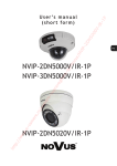
u s e r ’s m a n u a l NVR-5304POE NVR-5304POE User’s manual ver.1.1 IMPORTANT SAFEGUARDS AND WARNINGS EMC (2004/108/EC) and LVD (2006/95/EC ) Directives CE Marking Our products are manufactured to comply with requirements of following directives and national regulations implementing the directives: Electromagnetic compatibility EMC 2004/108/EC. Low voltage LVD 2006/95/EC with further amendment. The Directive applies to electrical equipment designed for use with a voltage rating of between 50VAC and 1000VAC as well as 75VDC and 1500VDC. WEEE Directive 2002/96/EC Information on Disposal for Users of Waste Electrical and Electronic Equipment This appliance is marked according to the European Directive on Waste Electrical and Electronic Equipment (2002/96/EC) and further amendments. By ensuring this product is disposed of correctly, you will help to prevent potential negative consequences for the environment and human health, which could otherwise be caused by inappropriate waste handling of this product. The symbol on the product, or the documents accompanying the product, indicates that this appliance may not be treated as household waste. It shall be handed over to the applicable collection point for the waste electrical and electronic equipment for recycling purpose. For more information about recycling of this product, please contact your local authorities, your household waste disposal service or the shop where you purchased the product. RoHS Directive 2002/95/EC Concerning for human health protection and friendly environment, we assure that our products falling under RoHS Directive regulations, regarding the restriction of the use of hazardous substances in electrical and electronic equipment, were designed and manufactured in compliance with mentioned regulation. Simultaneously, we claim that our products were tested and do not contain hazardous substances exceeding limits which could have negative impact on human health or natural environment. Information The device, as a part of professional CCTV system used for surveillance and control, is not designed for self installation in households by individuals without technical knowledge. The manufacturer is not responsible for defects and damages resulted from improper or inconsistent with user’s manual installation of the device in the system. ATTENTION! PRIOR TO UNDERTAKING ANY ACTION THAT IS NOT PROVISIONED FOR THE GIVEN PRODUCT IN ITS USER’S MANUAL AND OTHER DOCUMENTS DELIVERED WITH THE PRODUCT, OR THAT ARISES FROM THE NORMAL APPLICATION OF THE PRODUCT, ITS MANUFACTURER MUST BE CONTACTED OR THE RESPONSIBILITY OF THE MANUFACTURER FOR THE RESULTS OF SUCH AN ACTION SHELL BE EXCLUDED. All rights reserved © AAT Holding sp. z o.o. 2 NVR-5304POE User’s manual ver.1.1 IMPORTANT SAFEGUARDS AND WARNINGS 1. Prior to undertaking any action please consult the following manual and read all the safety and operating instructions before starting the device. 2. Please keep this manual for the lifespan of the device in case referring to the contents of this manual is necessary; 3. All the safety precautions referred to in this manual should be strictly followed, as they have a direct influence on user’s safety and durability and reliability of the device; 4. All actions conducted by the servicemen and users must be accomplished in accordance with the user’s manual; 5. The device should be disconnected from power sources during maintenance procedures; 6. Usage of additional devices and components neither provided nor recommended by the producer is forbidden; 7. You are not allowed to use the device in high humidity environment (i.e. close to swimming pools, bath tubs, damp basements); 8. Mounting the device in places where proper ventilation cannot be provided (e. g. closed lockers etc.) is not recommended since it may lead to heat build-up and damaging the device itself as a consequence; 9. Mounting the device on unstable surface or using not recommended mounts is forbidden. Improperly mounted device may cause a fatal accident or may be seriously damaged itself. The device must be mounted by qualified personnel with proper authorization, in accordance with this user’s manual. 10. Device should be supplied only from a power sources whose parameters are in accordance with those specified by the producer in the devices technical datasheet. Therefore, it is forbidden to supply the devices from a power sources with unknown parameters, unstable or not meeting producer’s requirements; 11. You cannot allow any metal objects get inside the recorder. It might cause serious damage. If a metal object gets inside the device contact the authorised Novus service immediately. 12. The manufacturer does not bear responsibility for damage or loss of data stored on HDDs or other media occurred during the usage of the product. Due to the product being constantly enhanced and optimized, certain parameters and functions described in the manual in question may change without further notice. We strongly suggest visiting the www.novuscctv.com website in order to access the newest manual . Technical changes reserved without prior notice and printing errors possible. All rights reserved © AAT Holding sp. z o.o. 3 NVR-5304POE User’s manual ver.1.1 TABLE OF CONTENTS TABLE OF CONTEST ............................................................................................. 4 1. FOREWORD INFORMATION ........................................................................ ..6 1.1. Network recorder’s technical data .................................................................. 6 1.2. Main characteristic ....................................................................................... ...7 1.3. Package contents ............................................................................................. 7 2. STARTING THE DEVICE .................................................................................. 8 2.1. Electrical connection and other rear panel elements. ..................................... 8 2.2. HDD mounting ............................................................................................... 8 2.3. Power connection.. ....................................................................................... 10 2.4. Connecting monitor ...................................................................................... 11 2.5. Camera and Network wiring......................................................................... 11 2.6. Peripheral device connection ........................................................................ 12 3. OPERATING NVR ............................................................................................. 12 3.1. Front panel description ................................................................................. 12 3.2. Controlling via USB mouse .......................................................................... 12 3.3. System operation .......................................................................................... 13 3.4. Startup configuration .................................................................................... 15 4. NVR MENU ......................................................................................................... 19 4.1. Live monitoring ............................................................................................ 19 4.2. Searching and playing recorded video .......................................................... 21 4.3. Backup ......................................................................................................... 22 4.4. PTZ ............................................................................................................... 23 4.5. Alarm ............................................................................................................ 23 4.6. Capture.......................................................................................................... 24 4.7. File manager ................................................................................................. 24 5. NVR CONFIGURATION .................................................................................. 25 5.1. Device ............................................................................................................ 25 5.1.1. Device info ............................................................................................ 25 5.1.2. Device version ...................................................................................... 26 5.1.3. PTZ setting ............................................................................................ 26 5.1.4. DST setting ........................................................................................... 27 5.2. Channel .......................................................................................................... 27 5.2.1. Display setting ................................................................................ 27 5.2.2. Video parameters ............................................................................ 28 5.2.3. Schedule recording ........................................................................ 29 5.2.4. Motion ............................................................................................ 30 5.2.5. Video lost........................................................................................ 31 5.2.6. Tampering alarm ............................................................................ 32 5.2.7. Video mask ..................................................................................... 33 All rights reserved © AAT Holding sp. z o.o. 4 NVR-5304POE User’s manual ver.1.1 TABLE OF CONTENTS 5.3. Network ......................................................................................................... 34 5.3.1. Network setting .............................................................................. 34 5.3.2. DDNS setting ................................................................................. 35 5.3.3. NTP setting .................................................................................... 36 5.3.4. E-mail setting ................................................................................. 37 5.3.5. Management platform .................................................................... 37 5.4. Alarm ............................................................................................................ 38 5.4.1. Alarm input .................................................................................... 38 5.4.2. Alarm output .................................................................................. 39 5.4.3. Exception ...................................................................................... 40 5.5. Account ......................................................................................................... 41 5.5.1. Account setting .............................................................................. 41 5.5.2. User online ..................................................................................... 43 5.6. System ........................................................................................................... 44 5.6.1. Device log ...................................................................................... 44 5.6.2. Stream info ..................................................................................... 44 5.6.3. HDD setting ................................................................................... 45 5.6.4. Update ............................................................................................ 45 5.6.5. Auto reboot .................................................................................... 46 5.6.6. Recovery configuration .................................................................. 47 5.7. Record ........................................................................................................... 48 5.8. Display setting............................................................................................... 48 5.9. Image setting ................................................................................................. 50 5.10. IP channel setting ........................................................................................ 51 5.10.1. Manual ......................................................................................... 51 5.10.2. Synchronization time ................................................................... 54 5.10.3. Manual synchronization ............................................................... 54 5.10.4. Changing channel sequence ......................................................... 54 6. NETWORK OPERATIONS UTILIZING WEB BROSWER ....................... 55 6.1. Recommended PC specification for web browser connections .................... 55 6.2. Establishing a connection.............................................................................. 55 6.3. Configuration of remote access..................................................................... 57 6.4. Live monitoring interface.............................................................................. 58 6.5. Searching and playing recorded video .......................................................... 60 6.6. Backup ......................................................................................................... 61 6.7. System setup ................................................................................................ 61 All rights reserved © AAT Holding sp. z o.o. 5 NVR-5304POE User’s manual ver.1.1 FOREWORD INFORMATION 1. FOREWORD INFORMATION 1.1. Network recorder’s technical data NVR-5304POE VIDEO / AUDIO Network Camera up to 4 channel in resolution 1920x1080(video + audio) Camera/Protocol suport NOVUS, ONVIF, RTSP Main (split screen, full screen, sequence): 1 x HDMI, 1 x VGA, Monitor Output Audio Output 1 x Line out Dualstreaming support Yes* RECORDING Compression H.264, MJPEG Resolution Up to 1920 x 1080 Speed Up to 120 fps (4 x 30fps for 1920 x 1080 and lower) Streams Size Up to 20Mb/s for the system Recording Mode Time-lapse, Event (Alarm, Motion detection), manual Schedule Individual settings for: each day, each hour, each camera, possibility of combining individual recording modes Prealarm/postalarm 0 s - 30 s/5 s - 600 s DISPLAY Resolution Up to 1920 x 1080 Speed Up to 120 fps (4 x 30fps)** PLAYBACK Up to 120 fps (4 x 30fps for 1280 x 960 and lower) Up to 30 fps (1 x 30fps for 1920 x 1080) Speed Recorded Data Search By date/time BACKUP Methods USB port (HDD or Flash memory), network File Format AVI STORAGE Internal HDD Installing 1 HDD 3,5” SATA Total Capacity 4 TB ALARM Camera Input/Output Support camera’s alarm input* Motion Detection Support camera’s motion detection* System Reaction to Alarm Events Buzzer, E-mail with attachment, output activation, screen message, recording activation, PTZ function NETWORK Network Interface 1 x Ethernet - RJ-45 socket, 10/100 Mbit/s + 4 x Ethernet - RJ-45 socket, 10/100/ Mbit with IEEE 802.3 af PoE Network Protocols Support ONVIF (2.2/Profile S), RTSP, HTTP, TCP/IP, IPv4, UPNP, UDP, SMTP, NTP, DHCP, DNS, DDNS, FTP PC Software Internet Explorer Smartphone Software MEye, MEyePro (for iPhone, Android) Number of Connections/Bandwidth Up to 4 connections / up to 20Mb/s for the system PTZ Functions Pan, tilt, zoom, preset * AUXILIARY INTERFACES USB 2 x USB 2.0 OPERATING SYSTEM Operating mode triplex OSD Polish, English and others Control PC mouse (in-set included), network System Diagnostic Automatic control of HDDs, network, network cameras lost Security Password protections, IP filtering, MAC filtering INSTALLATION PARAMETERS Dimensions (mm) 260 (W) x 45 (H) x 235 (L) Weight 1 kg (without HDD) Power Supply 48 VDC (100~240VAC/48VDC PSU In-set included) Power Consumption 96 W (with 1 HDD + 4 PoE cameras) Operating Temperature 0 °C ~ 50°C * Function capability depends on used communication protocol, for details please check full user manual. ** Available with using dual streaming mode All rights reserved © AAT Holding sp. z o.o. 6 NVR-5304POE User’s manual ver.1.1 FOREWORD INFORMATION 1.2. Main characteristics NVR-5304POE Up to 4 video and audio channels for network cameras Support ONVIF and RTSP protocol Recording speed up to 120 fps for 1920 x 1080 Supported resolution up to 1920 x 1080 Monitor output: HDMI, VGA, Support 1 HDDs 3,5” inside WARNING! ONVIF protocol support was verified with IP cameras based on ONVIF ver. 2.2 and compatible with the "PROFILE S". Implementation of the ONVIF protocol by different manufacturers may vary by some functions, which can make them work improperly or not in accordance with expectation. AAT HOLDING Company is not responsible for incompatibility problems resulting from cameras of other brands than NOVUS, which are using ONVIF protocol. If you are using ONVIF protocol cameras other than NOVUS brand it is recommended to test for each time whether required functions work correctly. 1.3. Package contents Unpack the device carefully. After unpacking, please ensure that package contains the following items: Network Video Recorder: NVR-5304POE Power supply 48VDC with cord USB Mouse Accessory bag with screw User’s manual (short) CD with a full version of user’s manual and software tools and software If any of the elements has been damaged during transport, pack all the elements back into the original packaging and contact your supplier. All rights reserved © AAT Holding sp. z o.o. 7 NVR-5304POE User’s manual ver.1.1 STARTING THE DEVICE 2. STARTING THE DEVICE 2.1 Electrical connection and other rear panel elements. 3 2 9 5 4 6 7 8 10 1. AOUT: Port for connecting local speaker with pre-amplifier. 2. AIN/SPEAK: Audio mono inputs for connecting microphones*. 3. 1080P (HDMI): Main monitor connectors, use the HDMI cable to connect monitor. 4. VGA: Main monitor connectors, use the D-SUB VGA cable to connect monitor. 5. USB: 2 x USB 2.0 ports for external Flash memory, mouse connection and other USB compatible devices. 6. LAN: RJ-45 connector port for connecting to the local network and interne 7. PoE : 4 x RJ-45 connections ports with PoE support 8. POWER SW: NVR power switch, plug the power cord and turn this switch on. 9. DC 48V: 48 VDC PoE power supply socket * for future usage Note: Back panels bottom USB port is shared with USB port at front panel (it is the same port), so you cannot use both ports at the same time. 2.2 HDD mounting Novus NVR support 1 internal SATA HDD. WARNING! In order to find information regarding the compatible models of HDDs and their maximum capacities, please contact Novus distributor or check the information presented at www.novuscctv.com. AAT HOLDING Company is not responsible for any problems resulting from using not recommended hard drives. The list of compatible HDDs contains all the HDDs that can be used with a given DVR including HDDs designed for office use - so called desktop disks. However, due to the fact that reliability of the recording process and data safety are paramount factors of any CCTV system, we strongly advise to use HDDs designed for continuous (24/7) operation. You need to format disks to if they were used in a different device. All data saved on HDD prior to format will be lost . All rights reserved © AAT Holding sp. z o.o. 8 NVR-5304POE User’s manual ver.1.1 STARTING THE DEVICE In order to mount HDD, please unscrew two screws on the NVR back side as depicted below and remove top cover Move cable tapes to the top, insert HDD under the cable and place HDD in dedicated place. Move NVR to the side holding HDD by hand, and screw it tightly. Then connect the power cable and data cable to the disk All rights reserved © AAT Holding sp. z o.o. 9 NVR-5304POE User’s manual ver.1.1 STARTING THE DEVICE Install the top cover on the NVR and screw it back. 2.3. Connecting power adapter. Please connect provided DC 48V adaptor in the rear power port of the NVR like depicted below. POWER SWITCH 48 V DC ADAPTER To start the unit turn on the power switch on back panel. Initialization lasts for approximately 60 seconds. During this time executing any device functions and pressing any buttons is prohibited. To shut down the device please use the menu. CAUTION: Make connection when the power is not applied. Do not place the power cord under the carpet or rug. The power cord is usually earth-grounded. However, even if it's not earth-grounded, never modify it on your own for earth-grounding. Make sure that power adapter is placed near of NVR and secured from accidental disconnection. CAUTION: If the device was brought from a location with lower temperature, please wait until it reaches the temperature of location it is currently in. Turning the device on immediately after bringing it from a location with lower ambient temperature is forbidden, as the condensing water vapour may cause short-circuits and damage the device as a result. All rights reserved © AAT Holding sp. z o.o. 10 NVR-5304POE User’s manual ver.1.1 STARTING THE DEVICE 2.4. Connecting monitor This product supports following interfaces for main monitor: HDMI, VGA. For HDMI and VGA outputs following resolutions are supported: 800x600, 1024x768, 1280x1024, 1366x768, 1440x900, 1920x1080 After changing resolution you have to confirm it by clicking YES. In case of monitor does not display anything please wait 8 seconds, then previous resolution will be restored. Note: You can use the HDMI <> DVI converter to connect to the DVI monitor. HDMI cable and HDMI<>DVI converter it’s not included and you have to buy it separately. 2.5. Camera and Network wiring NVR-5304 POE has 4 bulid-in RJ-45 ethernet ports with PoE support which can be used for connecting cameras. By using Ethernet cables connect the cameras and NVR to the switch, like on image below. Please notice that the Ethernet connection is effective within 100 meter distance. NOVUS NVR ETHERNET INTERNET SWITCH PC COMPUTER IP Before adding any camera to the NVR, you have to configure its network settings like it is described in Camera User Manual. For the next steps of camera and network configurations please check chapter 3.4. Startup configuration. Note: To ensure recording stability from an overloaded network traffic, or unauthorised access, it is strongly recommended to create separate network secured by router firewall from the user network. All rights reserved © AAT Holding sp. z o.o. 11 NVR-5304POE User’s manual ver.1.1 NVR OPERATING 2.6. Peripheral device connection Connecting audio ports Audio output signal normally are above 200mV 1kΩ. You can connect the low impedance earphone, or power amplifier with the external speakers. Connecting USB devices NVR has 2 x USB 2.0 ports for external Flash memory, mouse connection and other USB compatible devices. 2 USB ports (1x independent and 1x shared) are located at back panel and 1 USB port at front panel. Note: Back panels bottom port is shared with port at front panel (it is the same port), so you cannot use both ports at the same time. 3. NVR OPERATING 3.1. Front panel description 1 2 1. LED Shows power, recording, network connection or active alarm statuses. 2. USB USB 2.0 port for external Flash memory and mouse connection. 3.2. Controlling via USB mouse It is possible to control NVR via an USB mouse connected to the USB port. Double-clicking on any camera in 2x2, 3x3 display mode switches the display to full-screen mode. Subsequent double-click returns to previous display mode. Move cursor to the top or click the right key of mouse to bring up MAIN MENU and select START icon. Certain positions allow to select them via mouse scroll. Depending on NVR operating mode, pressing RMB displays a corresponding function menu. All rights reserved © AAT Holding sp. z o.o. 12 NVR-5304POE User’s manual ver.1.1 NVR OPERATING 3.3. System operations To start NVR plug power cable and switch on power button. The power led turns on. After booting, the video output default to multi-window output mode. By default NVR is using English language interface. To change language please follow the procedure like below: Move cursor to the top or click the right key of mouse to bring up MAIN MENU Select START icon Select User “admin”, leave password blank and confirm with OK button. and click the LOGIN icon to pop out the login menu: Default login is “admin” / no password. From the MAIN MENU click DISPLAY icon In LANGUAGE menu select preferred language. , following window will be shown: All rights reserved © AAT Holding sp. z o.o. 13 NVR-5304POE User’s manual ver.1.1 NVR OPERATING Save changes by clicking OK button New confirmation window will appear, choose YES to confirm Now NVR will start again with new language. To manipulate or access menus of the NVR, you should log in again. Move cursor to the top or click the right key of mouse to bring up MAIN MENU and select START icon Next click the LOGIN icon to pop out the login menu: Select User and enter the password . Use the virtual keyboard to enter the password and confirm with OK button. Default login is “admin” / no password. For safety reasons, it is recommended to change default user name and password. In order to shutdown NVR you should move cursor to the top or click the right key of mouse and select START icon . Next click the POWER OFF icon . After that use disable button at rear panel to turn off the power. In order to reboot NVR you should move cursor to the top or click the right key of mouse and select START icon . Next click the REBOOT icon . After NVR will boot again you should log in. To prevent unauthorized access, it is recommended to log out when you leave the screen. To do that move cursor to the top or click the right key of mouse and select START icon . Next click the LOGOUT icon . Note: When user is not login or has limited rights all inactive icon and menus are greyed out. CAUTION: If you turn off the system in an abnormal manner such as removing the power cord while the system is working, the disk will acquire or increase the numbers of bad sectors, causing data loss and shortened life cycle of the disk. All rights reserved © AAT Holding sp. z o.o. 14 NVR-5304POE User’s manual ver.1.1 NVR OPERATING 3.4. Startup configuration Prior to using NVR for the first time, initial setup is strongly advised. Before you connect the IP cameras to the NVR, please set up network and stream parameters of IP cameras in the right way. Note: For suggested values for IP camera setting please refer to the “Cameras Capability Table - appendix A" which is an integral part of this manual. If you will set wrong values some problems may appear: the NVR cannot search the IP camera, the stream cannot be connected, the image is not fluent, the image quality is bad and so on. To configure NVR please follow procedure like below: I. From the MAIN MENU click DISPLAY icon and set following parameters LANGUAGE - allow to select preferred language RESOLUTION - select the resolution most corresponding to the used monitor. II. From the MAIN MENU click SETTING icon and go to the SYSTEM section. Select HDD SETTING tab and check the hard drive. If it is unformatted you have to select it and press FORMAT button. III. From the MAIN MENU click SETTING icon DEVICE INFO tab and set following parameters: and go to the DEVICE section. Select DEVICE NAME - allow to add unique name for NVR VIDEO FORMAT - PAL or NTSC STREAM TYPE - depending on used cameras you have to chose correct mode from the list For eg. in mode 2x[1920*1080] + 2x[1280*720] + sub[960*576] + 1Ref + 4Play Channel 1 and 2 support 1920*1080, channel 3 and 4 support 1280*720, channel 1-4 sub streams support 960*576 resolution. 4Play means that there is possible to playback for 4 channels at once. 1Ref is internal buffer capacity. IV. DEVICE TIME - set up correct time and date and confirm by pressing MODIFY button From the MAIN MENU click SETTING icon and go to the NETWORK section. Select NETWORK SETTING tab and set following parameters: IP (by default it is 192.168.1.188) SUBNET MASK (by default it is 255.255.255.0). Note: Be sure that IP addresses and subnet mask of the NVR and the IP cameras are in the same network subnet (e.g. for the NVR IP address 192.168.1.188, and mask 255.255.255.0 appropriate address for the camera ranges from 192.168.1.1 to 192.168.1.254, for example 192.168.1.201). It is not allowed to set the same addresses for multiple devices. All rights reserved © AAT Holding sp. z o.o. 15 NVR-5304POE User’s manual ver.1.1 NVR OPERATING Optionally if you are going to connect NVR to the Internet (for remote access, sending email, etc) set up DEFAULT GATEWAY, FIRST and SECOND DNS. You can alternatively check DHCP mode (DHCP server is required in this method in target network) then all settings will be set up automatically. When you use DHCP server check IP address lease and its linking with NVR MAC address to avoid changing or losing IP address during device operation or network/DHCP server breakdown. This solution is not recommended for security systems. V. From the main window click the RMB and choose IP CHANNEL SETTING>MANUAL Then following window appears: To connect the IP cameras to the NVR you can find them automatically or type IP address manually. All rights reserved © AAT Holding sp. z o.o. 16 NVR-5304POE User’s manual ver.1.1 NVR OPERATING VI. Press SEARCH button to display all cameras present in network. After some time list of cameras appears. CHANNEL LIST SEARCH BUTTON ADD ALL BUTTON SEARCH RESULT WINDOW CHANNEL SETTING WINDOW To add required camera to the system TICK it on the list. Selected camera will be added to first empty channel. CHANNEL LIST is displayed at left hand side. If you press ALL button, all available channels will be connected with camera from the list. If you would like to remove camera added to one of the channels please select it at CHANNEL LIST “A” and press DELETE button “B” below: A B All rights reserved © AAT Holding sp. z o.o. 17 NVR-5304POE User’s manual ver.1.1 NVR OPERATING VII. Next you have to fill user name and password for each camera that you add to the NVR. Please double click at CHANNEL LIST “A” or select required channel from the CHANNEL dropdown menu ”B”. Next check if all settings for this channel are correct, fill username and password “C” and confirm by using SAVE button. Now you can select next channel from the dropdown menu. A B C If you set up the same user name and password and other parameters for all cameras you can simply type them and save for first channel, and then press COPY TO button, select required channels to copy them and confirm by OK button. Note that IP address is unique and doesn’t copy. B A After finishing following procedure NVR is ready to use. Additionally you should create user accounts for each operator. For event recording you should set up motion/alarm setting in the camera and modify SCHEDULE RECORDING and MOTION in the NVR. For event notification you should set up motion/alarm setting in the camera, configure NETWORK SETTING for using Internet and EMAIL SETTING All rights reserved © AAT Holding sp. z o.o. 18 NVR-5304POE User’s manual ver.1.1 NVR MENU 4. NVR MENU 4.1. Live monitoring Novus network video recorders features a multilingual OSD menu allowing for adjusting the settings of the device. Available languages are: English, Polish, and others As soon as the NVR completes its initialization process, it will enter the real-time monitoring image. Displaying all cameras simultaneously is the default mode. If you move mouse to the top MENU BAR will be shown. At the right corner of screen, shows the logged user and alarms status. In the bottom right corner of each channel image, shows capture and recording icon, zoom mode and alarm icon. MENU BAR MAIN MENU VIDEO WINDOW After login in, click the right key of mouse to bring up the MAIN MENU interface. You can also move mouse cursor to the window top display MENU BAR, which contains basic menu functions. Click icon to pop out the menu showed below: All rights reserved © AAT Holding sp. z o.o. 19 NVR-5304POE User’s manual ver.1.1 NVR MENU Click the right key of mouse to bring the MAIN MENU bar All rights reserved © AAT Holding sp. z o.o. 20 NVR-5304POE User’s manual ver.1.1 NVR MENU 4.2. Searching and playing recorded video To start the PLAYBACK MENU click icon. Then following window appears: VIDEO PLAYBACK WINDOW PLAYBACK BUTTONS CHANNEL SELECTION GRAPH WITH RECORDING SEARCH BUTTON CALLENDAR 1. From the CHANNEL SELECT tick the channel which you want to search the recording, it will auto search the recording . 2. Change the date from the calendar and press SEARCH button to find records for selected date. You can identify the type of the recording data by the color in the bar. Blue (Continuous) : continuous recording data. Red (Alarm) : alarm event recording data. Yellow (Motion) : motion event recording data. Pink (Motion or Alarm) : motion or alarm event recording data. Azure (Motion & Alarm) : motion and alarm event (when occurs in the same time) recording data. Green : data originating from manual recording. 3. To play the searched data simply double click a desired point on “Timeline” or press PLAY button. All rights reserved © AAT Holding sp. z o.o. 21 NVR-5304POE User’s manual ver.1.1 NVR MENU Description of playback buttons: Pause/Play: pause the current playback image. Stop: Stop the playing video. Slow: Slow down the playback speed. (there are: 1/2, 1/4, 1/8, 1/16 times) Fast: Accelerate playback. (there are: 2, 4, 8, 16 times) Snapshot: You can capture picture in any playback channel. Backup: You can backup the recording of any channel. 4.3. Backup User may copy recordings to external storage devices or through the network. The NVR features the possibility of copying the recordings to an external HDD connected via the USB, onto Flash memories. NVRs allow to copy the recordings in following formats: AVI. To start the BACKUP MENU click icon. Then following window will shown Insert USB storage device, click Refresh to detect the USB device. If the USB device is recognized normally, it will be displayed in the list, then select following: Select a required channels Select a date range filling FROM and TO range. Set the desired USB device for the backup. Choose the required file format. Press START button, process bar will move forward until reaches 100%. When it finish press UNMOUNT button and remove USB device. All rights reserved © AAT Holding sp. z o.o. 22 NVR-5304POE User’s manual ver.1.1 NVR MENU 4.4. PTZ PTZ button opens new window which allows to control the operations of a selected PTZ camera. To start the PTZ click icon. Then following window will shown Use it to adjust the pan, tilt, zoom and focus of the camera. You can also run and set Preset etc. Note: Not every camera model and network protocol allow to control camera remotely. 4.5. Alarm You can check the alarm log for events of particular interest. Click ALARM icon ing on the top. to display the “ALARM” window. The list is sorted with the latest events be- Use DEFENCE OFF button to disable alarm temporary. CLEAR ALARM button will remove all alarms from the list. All rights reserved © AAT Holding sp. z o.o. 23 NVR-5304POE User’s manual ver.1.1 NVR MENU 4.6. Capture If you would like to save some single image from camera click capture the channel image. Image file will be stored at hard disk. icon at the preview channel can Note: Capture works only with cameras supporting this functions. 4.7. File manager Menu allows to search and watch for the images captured manually, as well as delete or export them to a storage device. In this menu user can also search the storage device for the archived data and check the details of it or playback records. Click FILE MANAGER icon to open following menu: The default status is to show the capture image stored in the hard disk. To search images, select required channel, choose the date and press REFRESH button When need to playback the recording file or image from the external device, please click dropdown box to select the USB device from the drop-down list and search for files like previously. The file list column will show the file in the USB and captured image file on the NVR. All rights reserved © AAT Holding sp. z o.o. 24 NVR-5304POE User’s manual ver.1.1 NVR CONFIGURATION 5. NVR CONFIGURATION Setting menu allow to configure various NVRs parameters. 5.1. Device menu allows to check NVR information and configure the settings of date/time, system management, and peripheral device. 5.1.1. Device Info - check and modify the basic information of the NVR Following function are available: Device name - set device name Device ID - set up device unique number for remote controller Record Replace - if set to REPLACE, the existing data will be overwritten by newly recording data if the HDD free storage space is exhausted. If the option is set to STOP RECORD and the HDD is full, NVR will stop recording and notify via beep depending on the ALARM setting. Record Time - if ENABLE is on the available records will be limited by provided amount of hours. Panel Version - define front panel hardware version, do not modify it. RS 485 - set up functionality of RS485 interface Device info: contains current system information: Serial number, Channel, Alarm input, Alarm output, HDD number Video Format - switch between PAL and NTSC Stream Type - depending on used cameras you have to chose correct mode from the list For eg. in mode 2x[1920*1080] + 2x[1280*720] + sub[960*576] + 1Ref + 4Play Channel 1 and 2 support 1920*1080, channel 3 and 4 support 1280*720, channel 1-4 sub streams support 960*576 resolution. 4Play means that there is possible to playback for 4 channels at once. 1Ref is internal buffer capacity. All rights reserved © AAT Holding sp. z o.o. 25 NVR-5304POE User’s manual ver.1.1 NVR CONFIGURATION Protocol - enable / disable various IP cameras protocols. Device Time - set up current time and date, confirm by MODIFY button. Time and date format - allows to select different time and date formats 5.1.2. System Version - menu contains current system version info and hardware version 5.1.3. PTZ setting - configure the settings of the port for remote controller and peripheral devices. All rights reserved © AAT Holding sp. z o.o. 26 NVR-5304POE User’s manual ver.1.1 NVR CONFIGURATION 5.1.4. DST setting -user can specify the DST (Daylight Saving Time) settings. To ensure proper operation, set FROM time as last Sunday of March, 1:00 AM UTC. Clocks are moved forward at time defined in DST Bias. Set the TO time as last Sunday of October, 1:00 UTC. The clocks are moved back at time defined in DST Bias. 5.2. Channel - menu allow to configure camera settings, recordings parameters, alarm and motion events. 5.2.1. Display setting - configuration of camera image and display parameters. After selecting channel following parameters are available: Local Camera Name: You can modify the name and visibility for the specified channel . Camera Name: Allow to modify the OSD name and visibility of it remotely in camera, associated to the selected channel . All rights reserved © AAT Holding sp. z o.o. 27 NVR-5304POE User’s manual ver.1.1 NVR CONFIGURATION Time and date format - allows to select different time / date formats and enable visibility of it remotely in camera, associated to the selected channel. OSD Position: menu allows to select any position for the OSD remotely in associated camera. Image settings: user can set the brightness, contrast, saturation and hue remotely in associated camera. Sensor: set up various parameters remotely in camera, associated to the selected channel. Note: Not every camera model and network protocol allow to change all camera settings remotely. 5.2.2. Video Parameters - setting of streams parameters for every channel. After selecting CHANNEL and ENCODING STREAM following parameters are available: Stream type: select between Video or Video&Audio. Resolution: there is list of resolution available for current camera Bitrate type: select between CBR(constant) and VBR(variable). Bitrate: compression value for camera’s current stream Frame Rate: select different value from the drop-down list, the default value is “Full Frame”. Video Quality: select different image quality as needed (for VBR mode). I Frame interval: set the amount of frames for each I Frame. By using COPY TO button you can copy current settings to other required channel. Note: Not every camera model and network protocol allow to change all camera settings remotely. All rights reserved © AAT Holding sp. z o.o. 28 NVR-5304POE User’s manual ver.1.1 NVR CONFIGURATION 5.2.3. Schedule Recording - setting of different types of record plan for each channel. After selecting CHANNEL following parameters are available: Enable Recording: Tick the checkbox will start recording. All Day Recording: For using one type of recording tick the checkbox and select one of following: schedule, motion, alarm, motion or alarm, motion and alarm. It will start all day recording based of selection you have done. For using many type of recordings uncheck the checkbox and draw at schedule areas like is needed. It will start schedule recording based of current schedule. You can setup up to 8 separate time periods for each day/camera. Color schedule description. Blue (Continuous) : The continuous recording is performed on the recording data. Yellow (Motion) : The motion event recording is performed on the recording data. Red (Alarm) : The alarm event recording is performed on the recording data. Pink (Motion or Alarm) : If motion or alarm event occurs then recording is performed on the recording data. Azure (Motion & Alarm) :If motion and alarm event occurs in the same time then recording is performed on the recording data. Record Time: use it for advanced & precise schedule setting, by selecting days and typing times manually. Advanced: You can set the prerecord time and post record time. By using COPY TO button you can copy current settings to other required channel. All rights reserved © AAT Holding sp. z o.o. 29 NVR-5304POE User’s manual ver.1.1 NVR CONFIGURATION 5.2.4. Motion - menu allows to configure the built-in camera motion detection function. After selecting CHANNEL following parameters are available: Enable Motion Detection: Tick the checkbox will enable detection functionality. Area settings: select the motion detection area, press the left mouse button and drag to the area which you want to set motion detection, click OK. Sensitivity : set the sensitivity of detection Arm Schedule: set the time intervals when alarm is active. Setting: use it for advanced & precise schedule setting, by selecting days and typing times manually. All rights reserved © AAT Holding sp. z o.o. 30 NVR-5304POE User’s manual ver.1.1 NVR CONFIGURATION Linkage: select the reaction way for current which you need. Available reaction are: Audio warning (NVR internals buzzer), Email, Specified alarm output activation, Alarm on monitor and Alarm List, Trigger recording. By using COPY TO button you can copy current settings to other required channel. Note: Not every camera model and network protocol allow to change all camera settings remotely. 5.2.5. Video Lost - menu allows to define response of the NVR to video loss event on one of its video channels. Enable Video Lost: Tick the checkbox will enable detection functionality. Arm Schedule: set the time intervals when alarm is active. Linkage: select the reaction way for current which you need. Available reaction are: Audio warning (NVR internal buzzer), Email, Specified alarm output activation, Alarm on monitor and Alarm List. For detailed description of Arm Schedule and Linkage please check MOTION chapter. All rights reserved © AAT Holding sp. z o.o. 31 NVR-5304POE User’s manual ver.1.1 NVR CONFIGURATION 5.2.6. Tampering alarm - menu allows to configure the built-in camera tampering detection function. After selecting CHANNEL following parameters are available: Enable Video Tampering: Tick the checkbox will enable detection functionality. Area settings: select the detection area, press the left mouse button and drag to the area which you want to set, click OK to confirm. Arm Schedule: set the time intervals when alarm is active. Linkage: select the reaction way for current which you need. Available reaction are: Audio warning (NVR internals buzzer), Email, Specified alarm output activation, Alarm on monitor and Alarm List. For detailed description of Arm Schedule and Linkage please check MOTION chapter. Note: Function available in the future. Not every camera model and network protocol allow to change all camera settings remotely. All rights reserved © AAT Holding sp. z o.o. 32 NVR-5304POE User’s manual ver.1.1 NVR CONFIGURATION 5.2.7. Video Mask - menu allows to define masking zone on selected video channels. After selecting CHANNEL following parameters are available: Enable Video Mask: Tick the checkbox will enable detection functionality. Area settings: select the masking area, press the left mouse button and drag to the area which you want to set, click OK to confirm. Note: Function available in the future. Not every camera model and network protocol allow to change all camera settings remotely. All rights reserved © AAT Holding sp. z o.o. 33 NVR-5304POE User’s manual ver.1.1 NVR CONFIGURATION 5.3. Network - menu allow to configure network parameters of the device including email, DDNS and NTP setting . 5.3.1. Network setting - configuration of basic network parameters of the device. Following parameters are available: NIC Type: selection one of network interface (if additional network interfaces available). IP: enter the IP address. When the DHCP box is checked, the sub-fields: IP address, gateway, subnet mask, primary DNS server, secondary DNS server will be filled in automatically. When DHCP is off, user has to type fixed IP address and fill other network parameters. Using a fixed IP is recommended in order to achieve stable network operation. Subnet Mask: Enter the corresponding IP subnet mask. Default Gateway: Enter the corresponding gateway address. First/Second DNS: Enter the domain name servers IP address. MAC: Display the MAC address for current network interface Default route : chose the default network interface (if additional card available). Remote Port: enter port number used for sending data to the web browser or client software. HTTP Port: enter port number used for connecting to the NVR by web browser. Multicast: enter the corresponding multicast address. Enable Wi-Fi *: Tick the checkbox to enable and click “Wi-Fi” button to enter the setting interface. To enable Wi-Fi you have to connect a supported USB Wi-Fi card. Enable 3G *: Tick the box before “Enable 3G”, click “3G” to enter the setting interface. To enable 3G you have to connect a supported USB 3G modem. * Wi-Fi and 3G functionality will be available in the future. All rights reserved © AAT Holding sp. z o.o. 34 NVR-5304POE User’s manual ver.1.1 NVR CONFIGURATION Advance: additional menu contains: Enable PPPOE: you can enable the PPPOE service: Input the PPPOE user name, password dynamic address of the device Enable UPnP feature: will enable UPnP discovery function Note: Correct settings of IP address and subnet mask are necessary for proper operation of an IP camera. Defining gateways and DNS servers is necessary for using the camera outside the local network. 5.3.2. DDNS setting - configuration of Dynamic DNS service Enable DDNS: Tick the checkbox will enable detection functionality. Server Type: Allows to select a DDNS server that will be used in the DVR All rights reserved © AAT Holding sp. z o.o. 35 NVR-5304POE User’s manual ver.1.1 NVR CONFIGURATION Server Name and Port: values are set automatically after selecting Server Type User Name: requires entering the user’s name registered in the DDNS database. Password requires entering the DDNS-registered password. Domain requires entering hostname, that was registered in selected DDNS server. Note: Although the DVR supports dynamic IP addresses, it is advised that DDNS support should be performed at the local router that DVR is connected to. Prior configuration attempt please register the address in one of the DDNS servers supported by the device - www.dyndns.org server is advised. Prior to configuring the DDNS please contact the network administrator in order to obtain proper network parameters that are entered in this menu. 5.3.3. NTP setting - configuration of network time synchronization Enable NTP: Tick the checkbox will enable detection functionality. Server Address: set up required NTP server address NTP Port: set up required NTP server port (default is 123) Update Frequency: input the time interval needed to be adjusted Select Time Zone: choose the time zone valid for yours localization. GMT: allow to Daylight Saving Time adjustment, select ADJUST to enable. All rights reserved © AAT Holding sp. z o.o. 36 NVR-5304POE User’s manual ver.1.1 NVR CONFIGURATION 5.3.4. Email setting - menu responsible for Email account configuration Email Address: input the sender email address. Password: input the sender email password. PWD Confirm: confirm the password. SSL: tick to enable SSL authorization. Attachment: tic to add an image attachment to the email. Receiver: double click in selected field and type name and email address of the receivers (max 3). Delete : button to remove selected user and email address from the list. Interval: select the minimum time interval for sending emails. SMTP Server: input the SMTP server address. Port: input the SMTP server port. Note: Some email servers can block the email sending if the email delivery cycle is too short, and classify it as spam. Contact your email service provider to adjust the minimum delivery cycle so that the server does not classify the email as spam 5.3.5. Management platform - menu responsible for configuration of remote management service. Note: Feature available in the future All rights reserved © AAT Holding sp. z o.o. 37 NVR-5304POE User’s manual ver.1.1 NVR CONFIGURATION 5.4. Alarm - menu allow to define various events, and specify the conditions to notify the user. 5.4.1. Alarm input - configuration of the alarm sensor and specify the operation of the sensor if an event occurs. After selecting ALARM INPUT following parameters are available: IP address: display type of input, local mean internal in NVR, IP address number shows its camera alarm input. Alarm Name: you can specify the name of the alarm sensor Alarm Status: You can specify the type of the alarm sensor, N/O (Normal Open) or N/C (Normal Close) Alarm Handle: Tick the checkbox will enable reaction for current sensor. Arm Schedule: set the time intervals when alarm is active. Setting: use it for advanced & precise schedule setting, by selecting days and typing times manually. All rights reserved © AAT Holding sp. z o.o. 38 NVR-5304POE User’s manual ver.1.1 NVR CONFIGURATION Linkage: select the reaction way for current which you need. Available reaction are: Audio warning (NVR internals buzzer), Email, Specified alarm output activation, Alarm on monitor and Alarm List, Trigger recording, PTZ Linkage. By using COPY TO button you can copy current settings to other required channel. Note: Not every camera model and network protocol allow to change all camera settings remotely. 5.4.2. Alarm output - configuration of the alarm output and specify the behaviour of it. After selecting ALARM OUTPUT following parameters are available: IP address: allow to assign internal alarm input or external if available. All rights reserved © AAT Holding sp. z o.o. 39 NVR-5304POE User’s manual ver.1.1 NVR CONFIGURATION Delay: set the time reaction of it. Arm Schedule: set the time intervals when alarm is active. For detailed description of Arm Schedule please check Alarm input chapter. Note: Not every camera model and network protocol allow to change all camera settings remotely. 5.4.3. Exception - configuration of the alarm system events and specify the alarm reaction. Select EVENT TYPE and configure the reaction way for it which you need. Available types are: HDD Full: When there is no space in the HDD, it can trigger corresponding linkage type. HDD Fault: When there is HDD read and write fault alarm Network Broken: When there is network broken alarm. IP Address Conflict: When there is network IP conflict alarm. Illegal Access: When there is illegal access alarm. Video Signal Exception: When there is video signal abnormality. Available reaction are: Audio warning (NVR internals buzzer), Specified alarm output activation, Alarm on monitor and Alarm List. All rights reserved © AAT Holding sp. z o.o. 40 NVR-5304POE User’s manual ver.1.1 NVR CONFIGURATION 5.5. Account - menu allows to configure the settings regarding user management, as well as user and group permissions 5.5.1. Account Setting - You can add a user accounts and set up various permissions of them. To add a user account: Click ADD USER at the bottom of the screen. In new window please provide following values: User Name : enter user name. Password / Confirm Password: enter the password. User Typa: select a group that user belongs to: OPERATOR, GUEST, NONE. IP/MAC combine: provide IP address and MAC value for limiting access from network. When done, click OK. All rights reserved © AAT Holding sp. z o.o. 41 NVR-5304POE User’s manual ver.1.1 NVR CONFIGURATION To set up a user privilege: Select user on a list and click USER PRIVILEGE button. In new window please choose required access values for local and remote operation. When done, click OK. To modify a user information: Select user on a list and click MODIFY USER button. In new window please modify required values. When done, click OK. To delete a user information: Select user on a list and click DELETE USER button. In new window please confirm deleting user by YES. To apply changes, click OK or APPLY button at the bottom of the screen. All rights reserved © AAT Holding sp. z o.o. 42 NVR-5304POE User’s manual ver.1.1 NVR CONFIGURATION 5.5.2. User online - menu display information about local / remote user which are currently logged in. All rights reserved © AAT Holding sp. z o.o. 43 NVR-5304POE User’s manual ver.1.1 NVR CONFIGURATION 5.6. System - menu allows to configure the HDD, system management, and peripheral device. 5.6.1. Device Log - You can search the logs according to different types and different date and time, as shown in the above picture. Main Type of Log: there are All Type, Alarm, Exception and Operation for selection. Sub Type: according to different main types, there are corresponding sub types for selection. From: and To: you can select start and end time of a log you want to search. Search: press to display list of logs Export: allow export the log you have searched. Navigation buttons: allow to move pages 5.6.2. Stream Info - menu display information about cameras stream parameters All rights reserved © AAT Holding sp. z o.o. 44 NVR-5304POE User’s manual ver.1.1 NVR CONFIGURATION 5.6.3. HDD Setting - menu allow to format the HDD and view the HDD capacity, the free space and status etc Format - format the hard disk. Note that formatting the HDD will delete all video data and logs. 5.6.4. Update - menu responsible for upgrading NVR firmware To update firmware : Please connect the USB storage device that contains the update files placed in a root directory. Click BROWSE button. Select the correct file from the list with “.update” extension. All rights reserved © AAT Holding sp. z o.o. 45 NVR-5304POE User’s manual ver.1.1 NVR CONFIGURATION Click UPGRADE The progress bar displays the progress of the firmware upgrade process. When the upgrade is complete press OK reboot the system. Caution: Please contact your local distributor prior to software upgrade. Power outage, turning the device off or removing the Flash memory during update may result in damage to the NVR and a necessity of service repair. The producer isn’t responsible for any data loss resulting from firmware update. 5.6.5. Auto reboot - menu allow to set auto reboot feature, with selected frequency. Available values are: Every day: please select hour and minute in MAINTENANCE TIME Every Week: please select: - day of weeks in WEEKLY SHEDULE - hour and minute in MAINTENANCE TIME Once: please select a specific date and time in MAINTENANCE TIME All rights reserved © AAT Holding sp. z o.o. 46 NVR-5304POE User’s manual ver.1.1 NVR CONFIGURATION 5.6.6. Recovery configuration - menu responsible for saving and restoring default NVR settings Export Configuration: Save NVR settings to a storage device, connected to the USB port. Import Configuration: Load settings from a storage device connected to the USB port to the NVR Default: Return NVR settings to the factory default. All rights reserved © AAT Holding sp. z o.o. 47 NVR-5304POE User’s manual ver.1.1 NVR CONFIGURATION 5.7. Record - menu allows to quick change of recording behaviour. From the MAIN MENU click icon and set following parameters: Close - disable any recording at each of selected channel. Manual - enable continuous manual recording at each of selected channel. Schedule Record - allow to record depending of schedule setting for at each of selected channel. 5.8. Display Setting - Menu allow to select language, adjust screen colors and resolution, etc. From the MAIN MENU click icon and set following parameters Language - allow to select preferred language. Auto Logout - time interval for auto log out. All rights reserved © AAT Holding sp. z o.o. 48 NVR-5304POE User’s manual ver.1.1 NVR CONFIGURATION TV adjust - calibration of output video size and location. Display - settings of brightest, contrast, saturation and other monitor values. Resolution - select the resolution most corresponding to the used monitor. Enable SEQ - tick will enable camera image sequence. Rotation Interval - time interval of camera image sequence. All rights reserved © AAT Holding sp. z o.o. 49 NVR-5304POE User’s manual ver.1.1 NVR CONFIGURATION 5.9. Image Setting - Menu allow to adjust image parameters for selected channel From the MAIN MENU click icon and set parameters for selected camera image. Available parameters are brightest, contrast, saturation and hue. Note: Not every camera model and network protocol allow to change all camera settings remotely. All rights reserved © AAT Holding sp. z o.o. 50 NVR-5304POE User’s manual ver.1.1 NVR CONFIGURATION 5.10. IP channel Setting 5.10.1. Manual - menu allow to add and manage IP cameras connection. Note: For suggested values for IP camera setting please refer to the “Cameras Capability Table - appendix A" which is an integral part of this manual. If you will set wrong values some problems may appear: the NVR cannot search the IP camera, the stream cannot be connected, the image is not fluent, the image quality is bad and so on. From the MAIN MENU click icon and and choose MANUAL Then following window will shown: CHANNEL LIST CAMERA IP CHANGE PANEL SEARCH PANEL CHANNEL SETTING WINDOW To connect the IP cameras to the NVR you can find them automatically or type IP address manually. Note: Camera IP change functionality will be available in the future. All rights reserved © AAT Holding sp. z o.o. 51 NVR-5304POE User’s manual ver.1.1 NVR CONFIGURATION SEARCH PANEL - use it for search and add cameras to the NVR. Press SEARCH button to find all cameras present in network. After some time cameras list will appear. CHANNEL LIST SEARCH BUTTON ADD ALL BUTTON SEARCH RESULT WINDOW CHANNEL SETTING WINDOW To add required camera to the system TICK it on the list, then camera will be added to first empty channel. If you press ALL button then all available channels will be connected with camera from the list. CHANNEL LIST allow to manage cameras currently added to the system. A B If you would like to disable current channel please uncheck it at the list, connection with camera will be stopped intermediately. If you would like to remove camera added to one of the channels please select it at CHANNEL LIST “A” and press DELETE button “B”. All rights reserved © AAT Holding sp. z o.o. 52 NVR-5304POE User’s manual ver.1.1 NVR CONFIGURATION CHANNEL SETTING WINDOW - allow to set up network connection parameters. To modify network connections setting please double click at CHANNEL LIST “A” or select required channel from the CHANNEL dropdown menu ”B”. A B Next you have to modify connection parameters. Available setting are: -Protocol - select required communication protocol from the list - IP - IP address of the camera - Port - Communication port - For RTSP communication protocol enter IP address, RTSP port and stream PATH for main and sub stream. - Stream Type - select basic stream for watching and recording. - Network Type - select between TCP and UDP - Play Mode - select between smooth and real time video - User Name - camera user name - Password - camera password Confirm all settings by using SAVE button. CAMERA IP CHANGE PANEL - function available in the future. Note: If you set up the same user name and password and other parameters for all cameras you can simply type them and save for first channel, and next press COPY TO button to copy it to other required channel. All rights reserved © AAT Holding sp. z o.o. 53 NVR-5304POE User’s manual ver.1.1 NVR CONFIGURATION 5.10.2. Synchronization time - Menu allows to manage remote camera time synchronisation to the local NVR time. Following options are available: Automatic synchronisation - cameras time will be adjusted each time when necessary. Link synchronization - cameras time will be adjusted after successfully network link connections. Timing - cameras time will be adjusted each day at selected hour. Time - set time for camera synchronisation. Note: Not every camera model and network protocol allow to change all camera settings remotely. 5.10.3. Manual synchronization Function responsible for manual time synchronization. I case of selecting it local time of cameras will be set up the same like in NVR. 5.10.4. Changing channel sequence Drag to change channel sequence menu allow to change camera channel list order. TICK to enable function. Next, at split screen view drag the camera to the other one channel. Then both channels will be swapped. After finish remove TICK from the menu All rights reserved © AAT Holding sp. z o.o. 54 NVR-5304POE User’s manual ver.1.1 NETWORK OPERATIONS UTILIZING WEB BROSWER 6. NETWORK OPERATIONS UTILIZING WEB BROSWER Network Video Recorder features the possibility of controlling video data using network connections and web browser (Internet Explorer is recommended). 6.1. Recommended PC specification for web browser connections Requirements below apply to connection with an NVR, assuming smooth image display 4 channel in 1920x1080 resolution and 25 fps speed. Operating System Windows XP Professional, Vista Home Baisc / Premium, Windows 7 Web browsers: Internet Explorer 8.0 or later CPU Intel Pentium Core 2 Duo 3,16 GHz or higher Memory 1024 MB or more Display min. 16-bit 1280 x 1024 High Color Hard Disk Drive 50MB (space required for installing the web viewer software) 6.2. Establishing a connection Open the Internet Explorer browser . To connect to the NVR check the Network Setting and verify the IP and HTTP Port of the NVR (by default, IP address is 192.168.1.188). Enter the address in the address bar (web browser) of the local PC or dedicated software program in the format: http://IP_address (Ex : http://192.168.1.188) The web service port is set to 80 by default, if use other type address like: http://IP_address:web_service_port . From the Network Setting screen, you can change the port number. If login first time following window will be displayed: All rights reserved © AAT Holding sp. z o.o. 55 NVR-5304POE User’s manual ver.1.1 NETWORK OPERATIONS UTILIZING WEB BROSWER Click the given link and press Run button. If security warning window will be displayed press Run button. Web browser will download the applet for displaying images from the camera. After successfully plug in downloading run and install it on a computer. After successful installation, please reload web browser window. Following window should be displayed: Enable Compatibility View If web page will not load properly try to enable “Compatibility View” in Internet Explorer Provide the ID and password before logging in (Default is: ADMIN without password). Then, you can view the monitoring screen. If the installation fails, changing security settings for the IE browser is required. In order to do that, please choose: Tools > Internet options > Security tab > Custom level and: Under Download unsigned ActiveX controls - select either Enable or Prompt Under Initialize and script ActiveX controls not marked as safe - select Enable or Prompt All rights reserved © AAT Holding sp. z o.o. 56 NVR-5304POE User’s manual ver.1.1 NETWORK OPERATIONS UTILIZING WEB BROSWER You can also add the camera’s IP address to “trusted zone” and set lowest security level for it. In addition, when working in Windows Vista/7 the ActiveX applet may be blocked by Windows Defender or User account control. In such case you should allow to run this applet, or simply disable these functions. 6.3. Configuration of remote access If you are going to use Internet to remote connect with the NVR you need to have a Public IP Address (Static or Dynamic). Check your Network Provider if you don't know it. More over you have to configure NVRs NETWORK SETTING and Router in right way. For NVR you have to configure: IP and Subnet Mask - use value corresponding to your router IP address, check your Network Provider if you don't know them. Default Gateway - Yours Internet gateway (router) address, check your Network Provider if you don't know it. First and Second DNS - Check your Network Provider to get DNS addresses or use Public DNS like for eg. 208.67.222.222. To connect to the device by using Internet you have to create mapping of following ports: HTTP port: default number 80 Remote port: default number 5050 Remote data port: default number 5051 Remote data port: default number 5052 Mobile device port: default number 5053 In NVRs NETWORK SETTING menu you can configure HTTP and DEVICE PORT. REMOTE DATA PORTS are always DEVICE PORT value +1 and DEVICE PORT value +2. MOBILE DEVICE PORT is always DEVICE PORT value + 3. Depending of used Router Mapping Ports could be also named as Virtual Server or Port Forwarding. If you have an Dynamic IP Address you have to configure DDNS setting. Go to the DDNS setting chapter configure NVR like it is described. After proper configuration of the device you will be able to connect with it remotely. To check it try to use web browser typing in address: http://your_static_ip:http_port or use your DDNS address: http://your_ddns_domain:http_port. If everything correct then login window should be appear. All rights reserved © AAT Holding sp. z o.o. 57 NVR-5304POE User’s manual ver.1.1 NETWORK OPERATIONS UTILIZING WEB BROSWER 6.4. Live monitoring interface After successful logging into a user interface using IE web browser, the following window opens: MENU BAR VIDEO WINDOW MAIN MENU Whole interface is very similar to interface displayed on NVRs monitor. To enable camera live view choose OPEN ALL icon at selected camera window. Click from the MAIN MENU, or OPEN/CLOSE icon to pop out the menu showed below: All rights reserved © AAT Holding sp. z o.o. 58 NVR-5304POE User’s manual ver.1.1 NETWORK OPERATIONS UTILIZING WEB BROSWER Click the right key of mouse to bring the MAIN MENU bar * Feature available in the future All rights reserved © AAT Holding sp. z o.o. 59 NVR-5304POE User’s manual ver.1.1 NETWORK OPERATIONS UTILIZING WEB BROSWER 6.5. Searching and playing recorded video To start the PLAYBACK MENU click icon. Then following window appears: VIDEO PLAYBACK WINDOW PLAYBACK BUTTONS CHANNEL SELECTION GRAPH WITH RECORDING SEARCH BUTTON CALLENDAR 1. From the CHANNEL SELECT tick the channel which you want to search the recording, it will auto search the recording . 2. Change the date from the calendar and press SEARCH button to find records for selected date. You can identify the type of the recording data by the color in the bar. Blue (Continuous) : continuous recording data. Red (Alarm) : alarm event recording data. Yellow (Motion) : motion event recording data. Pink (Motion or Alarm) : motion or alarm event recording data. Azure (Motion & Alarm) : motion and alarm event (when occurs in the same time) recording data. Green : data originating from manual recording. 3. To play the searched data simply double click a desired point on “Timeline” or press PLAY button. All rights reserved © AAT Holding sp. z o.o. 60 NVR-5304POE User’s manual ver.1.1 NETWORK OPERATIONS UTILIZING WEB BROSWER Description of playback buttons: Pause/Play: pause the current playback image. Stop: Stop the playing video. Slow: Slow down the playback speed. (there are: 1/2, 1/4, 1/8, 1/16 times) Fast: Accelerate playback. (there are: 2, 4, 8, 16 times) Snapshot: You can capture picture in any playback channel. Backup: You can backup the recording of any channel. 6.6. Backup User may copy recordings to external storage devices or through the network. The NVR features the possibility of copying the recordings to an external HDD connected via the USB, onto Flash memories. NVRs allow to copy the recordings in following formats: AVI. To start the BACKUP MENU click icon. Then following window will shown Select a required channels Select a date range filling FROM and TO range. Select path for saving backup Choose the required file format. Press START button, process bar will move forward until reaches 100%. 6.7. System setup Setup menu contains most of NVR settings. Whole interface is very similar to interface displayed on NVRs monitor. For detail of each settings please refer “System Setup” description in chapter 5 - NVR CONFIGURATION. All rights reserved © AAT Holding sp. z o.o. 61 2014-08-07 MB AN AAT Holding sp. z o.o., 431 Pulawska St., 02-801 Warsaw, Poland tel.: +4822 546 07 00, fax: +4822 546 07 59 www.novuscctv.com