1
EDC-E Series AC Servo User's Manual
EDC-E series AC Servo User's Manual
(Version:V2.22)
-0-
EDC-E Series AC Servo User's Manual
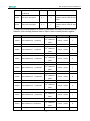
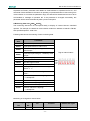
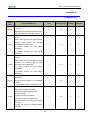
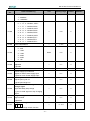
Revision History
Date
Rev. No.
Section
2007-09
V1.00
--
First edition
2008-2009
V1.11-V2.10
--
Completely revised
2010-07
V2.20
All chapters
8.3.3
2010-10
V2.21
Appendix A
2013-08
V2.22
--
Revised Content
Revision: change graph into vector graph
Revision: ModBus communication IO signal
(0900H)
Addition: remark③
Format update
-0-
Remark
EDC-E Series AC Servo User's Manual
General Precaution
Power supply voltage should be AC 220V.
The EDC servo system requires a power supply of AC 220V+/-15% voltage.
Do not connect the servo motor directly to local electric network.
It's prohibited to connect the servo motor directly to local electric network.Otherwise,the servo motor is
very likely to get damaged,The servo motor will not rotate without support of servo drive.
Do not plug in or unplug the connectors when the power is ON.
Internal circuit and motor encoder might be damaged if you plug in or unplug during power ON. Always
turn the power OFF first before plugging in or unplugging the connectors.
Wait for at least 5 minutes before doing inspection work on the servo system after turning power OFF.
Please note that even when the power is turned off, there will still be some electric energy remained in
the capacitors of the internal circuit. In order to avoid electrical shock, please make sure inspection work
is started 5 minutes after Charge indicator is OFF.
There should be a space of at least 10mm between the servo drive and any other devices mounted
in the electrical cabinet.
The servo drive produces heat when running, heat dissipation should be considered in the design of
mounting layout. At least 10 mm space in lateral direction and 50 mm space in longitudinal direction are
required from servo drive to other equipment during installation. Please install the servo drive in an
environment which is free from condensation, vibration and shock.
Noise immunity and grounding.
The noise from signal wires causes mechanical vibration and faults. Please comply with the following
rules:
- Run high-voltage power cables separately from low-voltage power cables.
- Make cables as short as possible.
- Single point grounding is required when mounting the servo motor and servo drive, and
grounding resistance should be lower than 100Ω.
- Please do not apply a input noise filter between servo drive and servo motor.
Voltage test of the servo drive should meet following conditions:
- Input voltage: AC 1500Vrms, 1 minute
- Interrupt/Break current: 100mA
- Frequency: 50/60Hz
- Forcing point: Between Terminal R, Terminal T and Terminal E.
Apply a fast-response leakage protector
It’s required to use a fast-response leakage protector or a leakage protector for a PWM inverter
designated by supplier. Do not use a time delay leakage protector.
Avoid extreme adjustments or changes
Don’t make extreme adjustments or changes to the servo drive’s parameters, which may cause
mechanical vibration and result in damage.
The servomotor cannot be operated by turning the power on and off.
Frequently turning the power ON and OFF causes the internal circuit elements to deteriorate, resulting in
unexpected problems. Always start or stop the servomotor by using reference pulses.
-2-
EDC-E Series AC Servo User's Manual
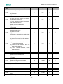
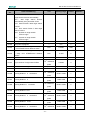
Contents
General Precaution ....................................................................................................... - 2 Contents ........................................................................................................................ - 3 Chapter 1 ...................................................................................................................... - 5 Checking products and product specification ................................................................ - 5 1.1 Checking products ........................................................................................... - 5 1.1.1 Servo motor ........................................................................................... - 5 1.1.2 Servo drive ............................................................................................. - 6 1.2 Servo components description ......................................................................... - 7 1.2.1 Servo motor ........................................................................................... - 7 1.2.2 Servo drive ............................................................................................. - 8 Chapter 2 ...................................................................................................................... - 9 Installation ..................................................................................................................... - 9 2.1 Servo motor ..................................................................................................... - 9 2.1.1 Storage temperature .............................................................................. - 9 2.1.2 Installation site ....................................................................................... - 9 2.1.3 Installation concentricity ......................................................................... - 9 2.1.4 Installation direction ............................................................................. - 10 2.1.5 Handling oil and water ......................................................................... - 10 2.1.6 Cable tension ....................................................................................... - 10 2.2 Servo drive ..................................................................................................... - 10 2.2.1 Storage condition ................................................................................. - 11 2.2.2 Installation site ..................................................................................... - 11 2.2.3 Installation orientation .......................................................................... - 11 2.2.4 Installation of several servo drives ....................................................... - 12 Chapter 3 ...................................................................................................................... - 5 Wiring ............................................................................................................................ - 5 3.1 Wiring and connection...................................................................................... - 5 3.1.1 Typical main circuit wiring ...................................................................... - 6 3.1.2 Names and Functions of Main Circuit Terminals .................................... - 6 3.2 I/O signals ........................................................................................................ - 7 3.2.1 Standard connection diagram ................................................................ - 7 3.2.2 Connector terminals ............................................................................... - 7 3.2.3 Function list of I/O signals ...................................................................... - 8 3.2.4 Interface circuit example ...................................................................... - 10 3.3 Encoder wiring ............................................................................................... - 11 3.3.1 Encoder wiring (2CN) ..................................................................... - 11 3.3.2 Signal list of connectors (2CN) ............................................................ - 12 3.4 Motor wiring ................................................................................................... - 12 3.4.1 Motor encoder terminals ...................................................................... - 12 3.4.2 Motor power terminal ........................................................................... - 13 3.5 Standard connection example ........................................................................ - 14 -
-3-
EDC-E Series AC Servo User's Manual
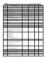
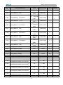
Chapter 4 .................................................................................................................... - 15 Function setting and description.................................................................................. - 15 4.1 Machine related settings ................................................................................ - 15 4.1.1 Servomotor rotation direction Select .................................................... - 15 4.1.2 Overtravel ............................................................................................ - 16 4.1.3 Stop function ........................................................................................ - 17 4.1.4 Limiting torque ..................................................................................... - 18 4.2 Settings complying with host controller .......................................................... - 19 4.2.1 Position control .................................................................................... - 20 4.2.2 Encoder output signal .......................................................................... - 26 4.2.3 Sequence I/O signal............................................................................. - 29 4.2.4 Electronic gear ..................................................................................... - 31 4.2.5 Position contact control ........................................................................ - 35 4.2.6 Zero adjustment ................................................................................... - 38 4.2.7 Parameter speed control ...................................................................... - 41 4.3 Servo drive settings ....................................................................................... - 44 4.3.1 JOG speed ........................................................................................... - 44 4.3.2 Control mode selection ........................................................................ - 44 4.4 Stop function settings ..................................................................................... - 45 4.4.1 Dynamic brake ..................................................................................... - 45 4.4.2 Holding brake ....................................................................................... - 46 4.5 Protection design ........................................................................................... - 50 4.5.1 Servo alarm output............................................................................... - 50 4.5.2 /S-ON input .......................................................................................... - 51 4.5.3 Positioning complete output ................................................................. - 52 4.5.4 Speed reached output .......................................................................... - 53 4.5.5 Handling instant power cut ................................................................... - 54 4.5.6 Regenerative braking unit .................................................................... - 55 4.6 Smooth running .............................................................................................. - 58 4.6.1 Smoothing ............................................................................................ - 58 4.6.2 Acceleration/deceleration time ............................................................. - 58 4.6.3 Speed detection smoothing time constant ........................................... - 59 4.6.4 Torque reference filter time constant .................................................... - 59 4.7 High speed positioning ................................................................................... - 60 4.7.1 Servo gain settings .............................................................................. - 60 4.7.2 Speed offset settings............................................................................ - 62 Chapter 5 .................................................................................................................... - 64 Troubleshooting .......................................................................................................... - 64 5.1 Alarm list ........................................................................................................ - 64 5.2 Alarm outputs and Troubleshooting ................................................................ - 65 5.3 Clearing alarms .............................................................................................. - 69 Chapter 6 .................................................................................................................... - 70 Panel Operator ............................................................................................................ - 70 6.1 Basic Function ............................................................................................... - 70 -
-4-
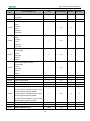
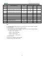
EDC-E Series AC Servo User's Manual
6.1.1 Function description ............................................................................. - 70 6.1.2 Resetting Servo Alarms ....................................................................... - 70 6.1.3 Display mode selection ........................................................................ - 71 6.1.4 Status Display Mode ............................................................................ - 71 6.1.5 Parameter Setting Mode ...................................................................... - 74 6.1.6 Monitor Mode ....................................................................................... - 75 6.2 Auxiliary functions .......................................................................................... - 77 6.2.1 Alarm history display ............................................................................ - 77 6.2.2 Restore to Defaults .............................................................................. - 78 6.2.3 JOG operation...................................................................................... - 78 6.2.4 Automatic offset signals adjustment of motor current detection ........... - 79 6.2.5 Servo software version display ............................................................ - 80 6.2.6 System runtime .................................................................................... - 80 6.2.7 Software version of panel operator ...................................................... - 81 6.2.8 Factory test .......................................................................................... - 81 6.2.9 Inertia Tuning/Checking ....................................................................... - 81 Chapter 7 .................................................................................................................... - 83 Trial operation ............................................................................................................. - 83 7.1 Inspection and checking before trial operation ............................................... - 83 7.2 JOG operation ................................................................................................ - 83 7.3 Trial operation in position control mode.......................................................... - 84 Chapter 8 .................................................................................................................... - 86 Communication ........................................................................................................... - 86 8.1 RS232 communication hardware structure .................................................... - 86 8.1.1 External connection diagram ............................................................... - 86 8.1.2 Cable connection ................................................................................. - 86 8.2 Communication relevant parameters ............................................................. - 87 8.3 MODBUS communication protocol ................................................................ - 90 8.3.1 Code signification................................................................................. - 90 8.3.2 Communication error handling ............................................................. - 96 8.3.3 Parameters, servo status data communication address ...................... - 97 Chapter 9 .................................................................................................................. - 102 Technical specification and features.......................................................................... - 102 9.1 Servomotor .................................................................................................. - 102 9.1.1 Technical specification and features .................................................. - 102 9.2 Servo drive ................................................................................................... - 104 9.2.1 Technical specification and model...................................................... - 104 9.2.2 Servo drive mounting dimension ........................................................ - 106 Appendix A ................................................................................................................ - 107 Parameter list ..................................................................................................... - 107 -
-5-
EDC-E Series AC Servo User's Manual
Chapter 1
Checking products and product specification
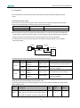
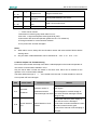
1.1 Checking products
The following procedure is used to check the AC servo drivers of EDC series products on delivery.
Check Items
Comments
Are the delivered products the ones that
Check the model numbers marked on the nameplates on the
were ordered?
servo motor and servo drive.
Does the servo motor shaft rotate
smoothly?
Is there any damage?
The servomotor shaft is normal if it can be turned smoothly
by hand. Servomotors with brakes, however, cannot be
turned manually.
Check the overall appearance, and check for damage or
scratches that may have occurred during shipping.
If any of above items is faulty or incorrect, contact your dealer from whom you purchased the products or
the service personnel of Estun.
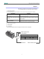
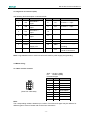
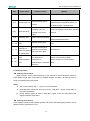
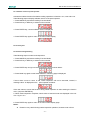
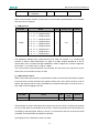
1.1.1 Servo motor
Nameplate
The following illustration shows an example of the servo motor’s nameplate.
Rated output power
Motor Model
AC SERVO MOTOR
MODEL EMJ-08APA
750 W
2.39 N·M
3000 r/min
4.00 A
200 V
CONT.
Ins. F
S/N
M000001Y20030409
Estun Automation Technology CO., Ltd.
Serial No.
-5-
Rated rotation speed
EDC-E Series AC Servo User's Manual
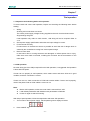
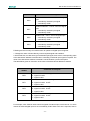
Servomotor Model Designation
EMJ
–
ESTUN Servomotor
08
A
【1+2】
【3】
P
【4】
A
【5】
1
【6】
1
【7】
EMJ Model
【1+2】Rated Output
Code
Rated Output
02
200W
04
400W
08
750W
10
1000W
【3】Voltage
Code
Voltage
A
200VAC
【4】Encoder
Code
Encoder
Wire-saving Incremental
P
Encoder(2500P/R)
【5】Designing Sequence
Code
Designing Sequence
A
Designing Sequence
【6】Shaft End
Code
Shaft End
1
Flat, Without Keys (Standard)
Flat, With keys, With Screw
2
Thread
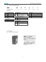
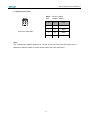
1.1.2 Servo drive
Appearance and Nameplate
-6-
【7】Option
Code
Option
1
None
2
With oil seal
3
With brake(DC 24V)
4
With oil seal and brake(DC 24V)
EDC-E Series AC Servo User's Manual
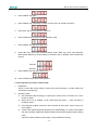
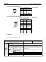
Servo drive Model Designation
EDC
–
08
A
P
E
EDC Model Servo Drive
Designing Sequence
E Designing Sequence
Rated Output Power
02 0.2kW
04 0.4 kW
08 0.75 kW
10 1.0 kW
Control Mode
P position control
Voltage
A 200VAC
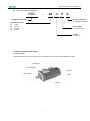
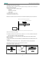
1.2 Servo components description
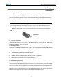
1.2.1 Servo motor
Following illustration shows the names of the components of a servo motor without gearbox and brake.
Nameplate
Mounting hole
Encoder
Output shaft
Shell
Flange
-7-
EDC-E Series AC Servo User's Manual
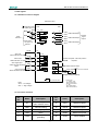
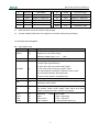
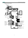
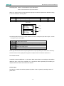
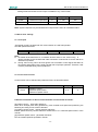
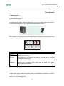
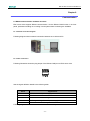
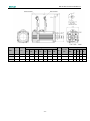
1.2.2 Servo drive
Following illustration shows the connections of the servo drive.
Charge indicator
Lights when the main circuit power supply is ON and stays lit as long as
the main circuit power supply capacitor remains charged. Therefore, do
not touch the servo drive even after the power supply is turned OFF if
the indicator is lit.
POWER&ALARM
Lights when power On, and in red when servo drive generates an
alarm.
CAN COM ID address selection switch
Set CAN communication address
CANBUS port(CAN)
CAN pin out
RS232 port(COM)
Communicating with a digital palm operator or a computer.
I/O signal connector(1CN)
Used for reference input signals and sequence I/O signals.
Encoder cable terminals(2CN)
To connect between motor and drive.
Servo motor terminals
To connect with the encoder on the servo motor.
Power supply terminals regenerative unit connection
-8-
EDC-E Series AC Servo User's Manual
Chapter 2
Installation
2.1 Servo motor
Servomotor can be installed either horizontally or vertically. However, if the servomotor is installed
with incorrect mechanical fittings, the servo motor’s lifetime will be greatly shortened and unexpected
accidents will occur.
Please make installation according to the instructions as below:
Precaution: There’s some antirust agent on the end of the motor shaft to prevent it from rusting
during storage. Please wipe off the agent thoroughly by using a cloth dipped with diluting agent or
thinners before installing the motor.
NOTE:The diluting agent should not touch any other parts of the servomotor when wiping the
shaft.
2.1.1 Storage temperature
When the servomotor is not in use, it should be kept in a place with an environment
temperature between −20°C and +60°C.
2.1.2 Installation site
Servomotor should be installed indoors, and the environment should meet following
conditions:
Free from corrosive, inflammable or explosive gases
Well ventilated and free from dust and moisture
Ambient temperature is between 0°C and 40°C
Relative humidity is between 26% and 80% RH (non-condensing)
Maintenance and cleaning can be performed easily
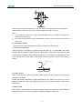
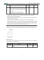
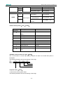
2.1.3 Installation concentricity
Use flexible shaft connectors as many as possible for mechanical connections. The axis centers of servo
motor and mechanical load should be kept in the same line. If a shaft connector is used when installing
servo motor, it has to meet the requirement of concentricity tolerance as shown in the illustration below.
Measure this at four quarter positions of a cycle. The difference between the maximum and minimum
measured value must be less than 0.03mm. (Rotate together with shaft connectors)
-9-
EDC-E Series AC Servo User's Manual
Measure this at four quarter positions of a cycle. The difference between the maximum and minimum
measured value must be less than 0.03mm. (Rotate together with shaft connectors)
Note:
If the concentricity tolerance is too big, mechanical vibration will occur, resulting in damage to the
bearings of the servo motor
Do not knock the axis direction when installing shaft connectors, this could damage the encoder of
servo motor.
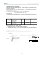
2.1.4 Installation direction
The servomotors can be installed, horizontally, vertically or in any direction.
2.1.5 Handling oil and water
If the servomotor is installed at a location subject to water, oil, or condensation, the motors
requires special treatment to meet protection requirements. If the motors are required to meet
the protection requirement before leaving the factory, it is necessary to designate the exact
motor models with oil seal. Shaft- cross-section means the gap as shown in the following
picture:
Shaft cross section
2.1.6 Cable tension
When connecting the cables, the bending radius should not be to small, do not apply big
pulling force to cables.
Please note that the diameter of signal cable wires is very small, from 0.2 mm to 0.3 mm,
therefore handle the cables with adequate care and do not cause excessive cable tension
while wiring.
2.2 Servo drive
EDC series of servo drives are all base-mounted. Incorrect mounting will cause problems.
Always mount the servo drives according to following installation instructions.
- 10 -
EDC-E Series AC Servo User's Manual
2.2.1 Storage condition
When the servo drive is not in use, it should be kept in an environment with a temperature
between -20 and +85°C.
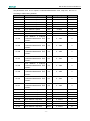
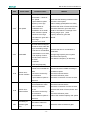
2.2.2 Installation site
Notes on installation of servo drive are as below:
Condition
Safety notes
A unified design for the cabinet size, configuration of servo
Installed inside a control
drive, and the cooling method is required so that the
cabinet
ambient temperature around the servo drive is always below
55 °C.
Installed near a heating unit
Minimize the heat radiating from the units by taking
advantage of heat dissipation measures such as natural
convection current, forced-air cooling, to ensure working
temperature around the servo drive is always below 55 °C.
Installed near a vibration
A vibration isolator should be mounted underneath the base
source
surface to prevent vibration.
Installed at a site exposed
Appropriate measures should be taken to prevent corrosive
to corrosive gases
gases from getting in. Corrosive gases does not have
immediate influence on the servo drive but they will
eventually cause problems on electronic components, which
will definitely have influence on the running stability of servo
drive.
Other situations
Do not install the servo drive in hot, humid locations or
locations subject to excessive dust or powder in the air.
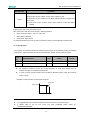
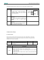
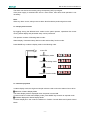
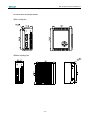
2.2.3 Installation orientation
As shown in the following picture, the installation direction should be vertically mounted onto
the wall, firmly fixed on the surface with two mounting holes.
Mounting
surface
Ventilation
A cooling fan can be mounted for forced-air cooling of the servo drive at request.
- 11 -
EDC-E Series AC Servo User's Manual
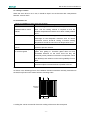
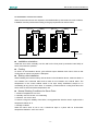
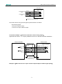
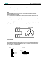
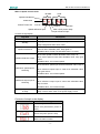
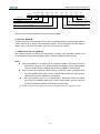
2.2.4 Installation of several servo drives
When several servo drives are required to be installed side by side inside one control cabinet,
installation must be performed according to the gap requirement as shown below:
Fan
Fan
50mm or more
50mm or more
30mm or more
10mm or more
Installation orientation
Install the servo drive vertically onto the wall so the front panel (connection board side) of
servo drive faces the operator.
Cooling
As shown in the illustration above, give sufficient space between each servo drive so that
cooling fans or natural convection is adequate.
Side-by-side installation
When installing servo drives side by side as shown in the illustration above, reserve at least 10
mm between two horizontal sides and at least 50 mm between two vertical sides. The
temperature in the control cabinet needs to be kept evenly distributed, subject to no
overheating at any part of servo drive. If necessary, install forced-air cooling fans above the
servo drives to avoid excessive temperature rise.
Normal Working Conditions for Servo Drive
1. Ambient Temperature: 0 to 55°C
2. Humidity: 90% RH or less, no condensing
3. Vibration: 4.9 m/s2 or less
To ensure a long term stability of the drive, it is suggested the drive be used in a place with a
temperature below 45 °C.
4. Storage condition
When the servo drive is not in use, it should be kept in a place with an environment
temperature between −20°C and +85°C.
- 12 -
EDC-E Series AC Servo User's Manual
Chapter 3
Wiring
3.1 Wiring and connection
Please observe the following instructions while wiring the main circuit.
!CAUTION
Do not run or combine power wires and signal wires together in the same conduit. There should
be at least 30 cm’s space between power wires and signal wires.
Shielded twisted pair wires are required for signal wires and encoder feedback wires, the shield
layer must be connected to the shell of the plugs.
Wire length requirement: reference signal input wires are maximum 3 meters, and encoder
feedback wires are 20 meters to the maximum.
Please note, even when the power is turned off, there will still be some electric energy
remaining in the internal circuit. In order to avoid electrical shock.
please make sure inspection or wiring work is started five minutes after Charge indicator is
OFF.
Do not turn power ON and OFF frequently. If required, turning power ON and OFF should be
controlled only once a minute.
There are some high capacity capacitors installed in the internal circuit of servo drive, when
power is switched on, a high charging electric current will flow though the capacitors within
several milliseconds, therefore, frequent power on/off will cause fast deteriation to the servo’s
internal elements.
-5-
EDC-E Series AC Servo User's Manual
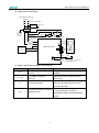
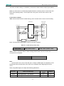
3.1.1 Typical main circuit wiring
Single phase AC220V
50/60Hz
+10%
-15%
Non-fuse circuit braker
Lightning protect
Surge
suppresser
Noise filter
Noise filter:
Design with
Europen
standard
PL
1RY
ON
1MC
OFF
Electromagnetic
contactor: Cutting off
electricity supply in
the emergence
1MC
1MC
(NO)
1MC
1RY
(NO)
Motor
U
V
W
R
T
E
M
EDC Servo drive
P
Regeneration
unit
Spark suppresser
Encoder
P
G
2CN
N
+24V
8
ALM
1RY
18 COM
0V Alarm output
OFF when alarm occurs
3.1.2 Names and Functions of Main Circuit Terminals
Terminal
R, T
U, V, W
Function
Description
Main circuit power supply input
Single-phase 220VAC(+10% / -15%) ,
terminal
50/60HZ
Servo Motor connection
Connects to power supply terminal of
terminals
servo motor
Connected individually to power supply
E
Grounding terminals
grounding terminals and servo motor
grounding terminal.
Connection terminals of external
P, N
regenerative unit
To connect an external regenerative unit.
(Note: prohibited to connect a
regenerative resistor directly between P
and N.)
-6-
EDC-E Series AC Servo User's Manual
3.2 I/O signals
3.2.1 Standard connection diagram
EDC Servo drive
P Represent multitwisted pair wire
PULS
Pulse
reference
SIGN
1CN
PULS
P
/PULS
SIGN
P
/SIGN
11
12
13
1
+24VIN
16
+
15
Alarm reset
/ALM-RST
(When ON alarm is reset)
6
ZPS
Zero point signal
(When ON,search for zero position)
8
150
2K
2K
Servo ON
(When ON servo function) /S-ON
/CLR
150
14
Power supply
for Open PL
collector
Clear signal input
(When ON,clear deviation
pulse)
2CN
PAO
Differential Output
/PAO
9
19
PBO
Differential Output
/PBO
10
20
PCO Differential Output
/PCO
Encoder
signal
output
3.3K
3
7
2
Position complete(ON when position
complete)
/COIN
/BK Brake interlock output
+24V
17
4
5
FG
Note:
ON: 0(Low voltage)
OFF: 1(High voltage)
18
Connector frame
Shield wire are connected to the connector frame
ALM Alarm output
OFF when alarm available
COM
(Output common point)
Photocoupler:
(1)/COIN、ALM
Max.voltage:DC30V
Max.current:DC50mA
(2)/BK
Max.voltage:DC30V
Max.current:DC80mA
3.2.2 Connector terminals
Pin.
No.
Name
Pin.
Description
Name
Description
11
PULS
Reference pulse
No.
Power supply for
1
PL
2
BRK
Remain braking
12
/ PULS
Reference pulse
3
COIN
Positioning complete
13
SIGN
Reference symbol
4
ALM
Alarm
14
/SIGN
Reference symbol
5
COM
15
S-ON
Servo enabled
open collector circuit
I/O common
grounding
-7-
EDC-E Series AC Servo User's Manual
6
ALM_RST
Reset Alarm
16
+24VIN
I/O power supply
7
CLR
Clear
17
ZPS
Zero position signal
8
PAO
Signal A(difference)
18
/PAO
Signal /A(difference)
9
PBO
Signal B(difference)
19
/PBO
Signal /B(difference)
10
PCO
Signal C(difference)
20
/PCO
Signal /C(difference)
Shell
FG
Connector's shell
Note:
Spare terminals can not be used for relay purpose.
Connect shielded cable wires of I/O signals to connector shell (frame grounding).
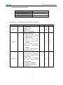
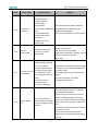
3.2.3 Function list of I/O signals
Input signal (1CN)
Signal
Pin no.
Function
Control power supply input for I/O signals: Users need to
+24VIN
16
prepare the +24V power supply.
Effective voltage range: +11V ~ +25V
S-ON
15
Servo ON:Servo motor is switched on
Select signal according to Pn051:
ALM-RST
6
CLR
7
ZPS
17
PL
1
(1CN-6 input signal selection)
0: ALM_RST, clear servo alarm status signal
1:CLR, clear offset counting in position control
2:P-CON,different meanings for different control modes
3:P-OT,forward direction limit signal input
4:N-OT,reverse direction limit signal input
According to Pn052, meaning as above
Zero position signal input: zero switch outputs this signal when
returning to zero position.
Reference open collector power supply:
To provide +5VDC power supply when PULS and SIGN
reference signals are open collector input signals.
PULS
11
Reference
pulse
/PULS
12
input:
*SIGN + Pulse train
SIGN
13
Line drive or
*CCW + CW Pulse
/SIGN
14
open collector
*2-phase positive pulse (×4)
-8-
Input modes:
EDC-E Series AC Servo User's Manual
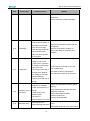
Output signal (1CN)
Signal
ALM
Pin no.
4
Function
Servo alarm: OFF status output is given when the drive detects an
error.
The value of Pn050 decides the output signal, see the details as
follows:
0: brake interlock(BK) output; positioning complete/same speed
detected; in position control method it means positioning is
completed(COIN), while in speed control method it means same
speed is detected(V-CMP).
1: positioning complete/same speed detected; in position control
COIN
3
method it means positioning is completed(COIN), while in speed
control method it means same speed is detected(V-CMP)
2: torque limit CLT output: when output torque exceeds the value of
Pn026 or Pn027, this signal gives output.
3: Servo ready S-RDY output: When servo drive detects no alarm
subject to a power supply input, this signal gives output.
4: Encoder C-pulse signal output: One C-pulse signal output per
revolution.
The value of Pn049 decides the output signal, see the details as
follows:
0: brake interlock(BK) output
1: positioning complete/same speed detected; in position control
method it means positioning is completed(COIN), while in speed
BK
2
control method it means same speed is detected(V-CMP)
2: torque limit CLT output: when output torque exceeds the value of
Pn026 or Pn027, this signal gives output
3: Servo ready S-RDY output: When servo drive detects no alarm
subject to a power supply input, this signal gives output.
4: Encoder C-pulse signal output: One C-pulse signal output per
revolution.
COM
5
PAO
8
/PAO
18
PBO
9
/PBO
19
PCO
10
/PCO
20
FG
Shell
I/O common grounding
Differential output of Encoder A signals
Differential output of Encoder B signals
Differential output of Encoder C signals
Connect shielded wires of I/O signal cables to shell of 1CN, which is
equal to the connection of the shell and the frame grounding wire.
-9-
EDC-E Series AC Servo User's Manual
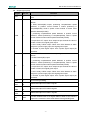
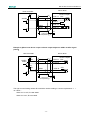
3.2.4 Interface circuit example
Following illustrations show the connection of I/O signals of servo drive and host controller:
■ Input interface circuit
Following illustrations show an example of the connection of input signals using relay contact
or open collector transistor circuit.
Servo drive
Servo drive
DC24V
50mA or more +24VIN 3.3KΩ
DC24V
50mA or more
+24VIN
/S-ON
3.3KΩ
/S-ON
If the relay contact input is used, the relay must be suitable for low electric current, otherwise it
causes signal receiving faults.
■ Interface of encoder output and drive output
Output signals (PAO,/PAO,PBO,/PBO) of the two phase pulse of the encoder and the origin
pulse signal(PCO, /PCO) make the outputs by means of BUS drive output circuit. Generally,
it's used on the condition that the host controller side forms the position control system. Wire
reception circuit should be used when it's near the host controller.
See "Encoder wiring" for an example of a practical circuit connection.
■ Interface of sequence output circuit
Photo-coupling isolation output is required for output signals of servo alarm, positioning
complete and brake interlock.
DC5V~24V
Relay
Servo drive side
0V
- 10 -
EDC-E Series AC Servo User's Manual
Note:
Maximum voltage should be no more than 30VDC, and maximum current should be no more
than 50mA.
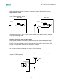
3.3 Encoder wiring
3.3.1 Encoder wiring (2CN)
Incremental encoder
EDC Servo drive
*
5
1CN
2CN
4
P
6
7
8
P
9
P
PA
2-3
/PA
2-4
PB
2-1
/PB
PC
2-2
2-8
/PC
2-9
Encoder A pulse
Encoder B pulse
Encoder C pulse
PG
*
2-8
PAO
2-18
/PAO
2-9
PBO
2-19
/PBO
2-10
PCO
2-20
/PCO
Output line-drive
Equivalent product of
AM26LS31
2
3
PG5V
GND
1
2-7
2-14
PG5V
PG0V
FG
Shield wire
*
(Host controller)
Connector shell
Connector shell
P Represent multi-twisted shield wire
Note:
The sequence No. of encoder pin’s corresponding relation with signal will change because of different types of motors .
- 11 -
P
P
P
Line receiver
equivalent product of
SN75175
EDC-E Series AC Servo User's Manual
3.3.2 Signal list of connectors (2CN)
See following list for description of 2CN terminals.
Pin No.
Name
1
PB
2
/PB
3
PA
4
/PA
5
-
6
-
7
PG5V
Comments
Pin No.
Name
8
PC
Encoder C+ input
9
/PC
Encoder C- input
10
-
--
11
-
--
--
12
-
--
--
13
-
--
14
GND
Encoder B+
Input
Encoder B-
input
Encoder A+
input
Encoder A-
input
Encoder power
supply +5V
FG
Comments
Encoder power supply
grounding
Connect shielded wires
to shell of connectors.
Note: Large diameter wires or multi-core wires are used for power supply and grounding.
3.4 Motor wiring
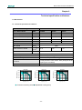
3.4.1 Motor encoder terminals
Shell:172169-1 (AMP)
Pin: 170359-3 (AMP)
Incremental type
Pin. No. Signal
Color
3 2 1
6 5 4
9 8 7
(View from cable side)
1
A+
Blue
2
B+
Green
3
C+
Yellow
4
A-
Blue/Black
5
B-
Green/Black
6
C-
Yellow/Black
7
PG5V
Red
8
PG0V
Black
9
FG
Shield
Note:
The corresponding relations between pin number of encoder and signal may be different for
different types of motors. Please refer to the motor instructions.
- 12 -
EDC-E Series AC Servo User's Manual
3.4.2 Motor power terminal
Shell:172167-1 (AMP)
Pin: 170360-1 (AMP)
2 1
4 3
(View from cable side)
Pin NO.
Signal
Color
1
U
Red
2
V
Blue
3
W
White
4
FG
Green/Yellow
Note:
The corresponding relations between pin number of motor’s power wire and signal may be
different for different models of motors. Please refer to the motor instructions.
- 13 -
EDC-E Series AC Servo User's Manual
3.5 Standard connection example
Single Phase AC220
50/60Hz
+10%
-15%
Non-fuse circuit breaker
Lightning protect
Surge
suppresser
Noise filter
PL
1RY
ON
Noise filter:
Design with
European
standard
1MC
OFF
1MC
1RY
Spark suppresser
Motor
1MC
1MC
U
V
W
R
T
FG
EDC Servo drive
P
Regenration
M
Encoder
P
G
2CN
N
Represents multi-twisted wire
PULS
P
PULS
/PULS
SIGN
Position
SIGN
P
reference
/SIGN
P
Power supply
for open PL
collector
+24VIN
11
12
150
8
13
150
18
9
ALM-RST
Clear deviation
(Clear when ON)
CLR
Zero point signal
(Search zero position
when ON)
ZPS
PBO
/PBO
10
1
CAN
16
PG dividing
ratio output
PCO
/PCO
20
2K
1
2
3
4
GND
CANH
CANL
FG
1
2
3
4
VCC
TXD
RXD
GND
COM
3.3K
S-ON
PAO
/PAO
19
14
+
Servo ON
(Servo ON When ON)
Alarm reset
(Reset when ON)
Please handle connector
of shield wires properly
1CN
15
COIN positioning complete
(ON when positioning completes)
BK brake interlock output
(ON when BK signal output)
3
6
*
7
2
CLT torque limit output
(ON when exceed preset value)
S-RDY servo ready
(ON when ready)
C-Pulse Encoder C-Pulse output
17
+24V
4
5
ALM Alarm output
0V
OFF for an alarm
Photocoupler:
Max.Voltage DC30V
Max.Current DC50mA
FG Connector sheild
Connect sheild to connector shell
- 14 -
*The functions allocated to the output
signals Pin3 to Pin4 can be changed by
using the parameters.
EDC-E Series AC Servo User's Manual
Chapter 4
Function setting and description
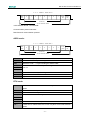
4.1 Machine related settings
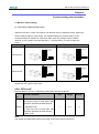
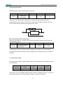
4.1.1 Servomotor rotation direction Select
With the servo drive, a motor can rotate in one direction which is called REV mode, without any
need to make changes in motor wiring. The standard setting for “forward rotation” is the
counterclockwise as viewed from motor load. REV mode only changes motor’s rotation
direction, in this condition, the travel direction(+,-) of shaft rotation, no other changes are
made.
Standard mode
Reverse mode
Encoder signal
feedbacked from
motor
Encoder signal
feedbacked form
motor
FWD Run Ref.
CCW
Phase A
CW
Phase A
Phase B
Phase B
Encoder signal
feedbacked from
motor
REV Run Ref.
CW
Encoder signal
feedbacked from
motor
Phase A
Phase A
CCW
Phase B
Phase B
The encoder signals by motor feedback as shown in above diagrams are the PA,/PA,PB,/PB
signals from PG output of servo drive.
■ Set “REV mode”
Rotation direction of motor is selected by setting the parameter as follows.
Para.
No.
Name & Comments
Unit
Range
—
0~1
Default
Select rotation direction
[0] view from side of motor load, CCW
direction represents forward direction.
Pn006
(standard mode)
[1] view from side of motor load, CW
direction represents forward direction.
(REV mode)
Note:
The change only takes effect when motor power is shut down and re-powered on.
- 15 -
0
EDC-E Series AC Servo User's Manual
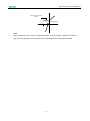
4.1.2 Overtravel
The overtravel limit function stops movable machine parts when they exceed the allowable range of
motion.
■ Overtravel function setting
Before using overtravel function, please connect correctly the input signals of following overtravel limit
switch to the corresponding pin numbers of servo drive’s 1CN connector.
Input P-OT
1CN-6
Pn001=0,Pn051=3
Forward direction rotation is prohibited
input N-OT
1CN-7
Pn002=0,Pn052=4
Reverse direction rotation is prohibited
EDC servo drive have only one overtravel input signal (1CN-6), so users can only select overtravel limit in
a single direction. Please be aware that when you are running the system for the first time it’s required to
identify forward and reverse direction before making settings in the overtravel parameter.
It is advised that the user connects the limit switch according to following diagram to avoid possible
mechanical damage.
Reverse
Forward
Servo drive
Servo motor
Limit switch
P-OT
1CN-6
N-OT
1CN-7
Following table shows the drive status when input signal is ON and OFF.
Signal
Status
ON
P-OT
OFF
ON
N-OT
OFF
Parameter
Pn001=0
Pn051=3
Pn001=0
Pn051=3
Pn002=0
Pn052=4
Pn002=0
Pn052=4
Input level
Comments
1CN-6:’L’ level
Forward direction is allowed. (Normal)
1CN-6:’H’ level
1CN-7:’L’ level
1CN-7:’H’ level
Forward direction is OFF. (Reverse
direction is available)
Reverse direction is ON. (Normal)
Reverse direction is OFF. (Forward
direction is available)
■ Switching between Enable/Disable overtravel input signal
By setting the parameter as in the following table, user may select Enable or Disable the overtravel input
signal. Default is “ON”.
Para.
No.
Description
Unit
Setting
range
Default
Enable/Disable input signal prohibited (P-OT)
Pn001
When 1CN is set as P-OT signal, limiting direction
and enable are selected according to this parameter.
- 16 -
—
0~1
0
EDC-E Series AC Servo User's Manual
[0] Enable forward run input signal prohibited
[1] Disable forward run input signal prohibited
Enable/Disable input signal prohibited (N-OT)
When 1CN is set as N-OT signal, limiting direction
and enabling are selected according to this
Pn002
parameter.
—
0
0~1
[0] Enable reverse run input signal prohibited
[1] Disable reverse run input signal prohibited
Notes:
1. When the motor is stopped by the overtravel in position control mode, there is no pulse lag.
2.After overtravel, motor is in excitation state.
3. Only one overtravel direction can be used, make sure overtravel direction is set before using this
function. (subject to actual running)
4. Please be aware, the overtravel signal does not work if a motor is running in JOG mode.
5. During mechanical movement, when an overtravel signal occurs, mechanical parts do not stop
immediately owing to the action of their own inertia. In this situation, the overtravel signal is canceled
and the motor will continue running. Please pay close attention to the duration of the overtravel signal,
make sure there is some distance for overtravel signal on the machine.
When “P-OT” and “N-OT” are not used, the short circuit wiring as shown in the following diagram will not
be required. Another way is to shield this with parameter, use may set Pn001 as 0 or set Pn052.bit=0.
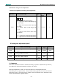
4.1.3 Stop function
■ Select stop mode
When servo is OFF or servo alarm occurs, the following “User Constants” should be set according to the
actual requirements on stopping the motor.
Parameter No.
Pn004
Function
Stop modes when servo is on or servo alarm
occurs.
- 17 -
Range
Default
0~3
0
EDC-E Series AC Servo User's Manual
Parameter No.
Comments
[0] When servo is OFF or alarm occurs, DB is enabled
[1] When servo is OFF or alarm occurs, motor coasts to a stop
[2] When servo is OFF or alarm occurs, DB is enabled and will not release until
Pn004
motor stops
[3] When servo is OFF or alarm occurs, motor coasts to a stop, then DB is
enabled.
■ Select motor stop mode when servo is OFF.
EDC series servo drive stop motor running in following situation:
When /S-ON input signal(1CN-15)turns OFF
When alarm is detected
When power supply is OFF
To select appropriate stop mode, set value of Pn004 according to actual application requirements.
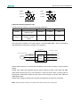
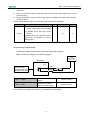
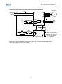
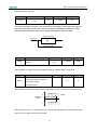
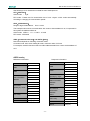
4.1.4 Limiting torque
For protection of mechanical structures, maximum output torque can be limited by setting the following
parameters to adjust the maximum value of forward/reverse direction torque on the servo drive.
Para.
Name & Function
Unit
Range
Default
Pn026
Forward internal torque limit
1%
0~300
250
Pn027
Reverse internal torque limit
1%
0~300
250
No.
Set maximum torque for forward and reverse direction, it’s used when limiting torque is
required according to mechanical requirements.
If value of current torque exceeds motor’s maximum allowable torque, follow the maximum
torque of motor.
Example to show protection of mechanical structures
Torque limit
Motor speed
Torque
Note:
It’s suggested the value of limited torque should not exceed motor’s maximum torque.
If
limited
value
is
set
too
low,
motor
may
acceleration/deceleration.
- 18 -
have
insufficient
torque
during
its
EDC-E Series AC Servo User's Manual
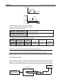
4.2 Settings complying with host controller
Different control modes can be selected by setting Pn041 as described in the following table.
Para. No.
Name
Range
Default
Select control mode
Pn041
Comment
position control, position
[0] position control
0~2
[1] internal speed control
0
contact control, and
parameter speed control
[2] parameter speed control
Set Pn041 and select a certain control mode.
Pn041 setting
Control mode
Position control(pulse reference)
0
Servo drive receives pulse train generated by host controller, and the control of
rotation speed and positioning are achieved according to requirements from the
host controller.
1
2
contact speed control(I/O reference)
Running at set speed is selected by switch on/off input signals.
parameter speed control(parameter reference)
Run at constant speed as the value in Pn048.
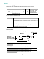
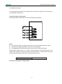
Using the CLT signal
Following illustration shows the way to use the contact output signal/CLT(torque limit test).
24V Power supply
Servo drive
+24V
/CLT+
Photocoupler
Max.voltage:DC30V
Max.current:DC50mA
->output /CLT
/CLT-
Torque limit detection
Speed control, torque control,
output
position control
The following signal can be output to indicate the servomotor output torque is being limited or not.
/CLT
“L” level when ON
The servomotor output torque is being limited.
(internal torque reference is above setting value)
/CLT
“H” level when OFF
The servomotor output torque is not being limited.
(internal torque reference is below setting value)
- 19 -
EDC-E Series AC Servo User's Manual
The setting value:Pn026(Forward direction torque internal limit)
Pn027(Reverse direction torque internal limit)
When /CLT signal is used, the output signal and output pin number are required to be defined according
to the user constants in following table.
Para. No.
Name & Description
Range
Default
Pn049
Output signal 1CN-2 pin No. signification
0~4
0
Pn050
Output signal 1CN-3 pin No. signification
0~4
1
Servo drive
Pn049=0:
Pn049=1:
Pn049=2:
Pn049=3:
Pn049=4:
COIN/V-CMP
BK
CLT
S-RDY
C-Pulse
Pn050=0:
Pn050=1:
Pn050=2:
Pn050=3:
Pn050=4:
COIN/V-CMP
BK
CLT
S-RDY
C-Pulse
1CN-2
Output
1CN-3
The following table shows the pin number definition for Pn049(correspond to pin 1CN-2 output), Pn050
(correspond to pin 1CN-3output).
0
BK brake interlock output
1
COIN positioning complete(/V-CMP speed coincidence) output
2
CLT torque limit output
3
S-RDY servo ready output
4
Encoder C Pulse Output(This signal couldn't be inverted)
Please pay attention that encoder C pulse signal which is output by relative pin number will be affected by
external circuit,since the signal gets through photo coupler,if Pn049 or Pn050 are selected as 4.
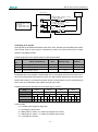
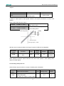
4.2.1 Position control
In position control mode(Pn041=0), the servo drive make drive runs according to the position
reference given by the host controller. It is required to select optimal input according to
requirements of the host control device as follows.
■ Pulse input
Host device controls the rotation speed and position of servo system by sending a series of
pulse trains.
- 20 -
EDC-E Series AC Servo User's Manual
Servo drive
Photo coupler
PULS
Pulse reference
input
/PULS
P
1CN-11 150
1CN-12
Pulse direction
input
SIGN
/SIGN
P
1CN-13 150
1CN-14
PRepresents multi-twisted wire
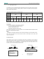
Host control device may give three types of pulse reference as follows:
- linear driving output
- +24V open collector output
- +12V and +5V open collector output
Connection example 1(when host controller is linear driving output)
Applicable linear drives(T1 company AM26LS3, SN75174 or MC3487 and other substitutes.)
Servo drive
Host controller
Photo-coupler
PULS
/PULS
SIGN
/SIGN
P
1CN-11 150
1CN-12
P
1CN-13 150
1CN-14
Grounding
FG
Connect to
shell(shielding)
Example 2(When host device is open collector output subject to 24VDC signal power)
- 21 -
EDC-E Series AC Servo User's Manual
Servo drive
Host controller
Vcc
Photo-coupler
PULS
24VDC
/PULS
1CN-11
1CN-12
P
1CN-1
SIGN
/SIGN
2K
1CN-13
1CN-14
P
Grounding
150
150
FG
Connect to
shell(shielding)
Example 3(When host device is open collector output subject to 12VDC or 5VDC signal
power)
Servo drive
Host controller
Vcc
12VDC
5VDC
R1
PULS
/PULS
Photo-coupler
i
P
1CN-11 150
1CN-12
P
1CN-13 150
1CN-14
Vcc
R1
SIGN
/SIGN
Grounding
FG
Connect to
shell(shielding)
The right current limiting resistor R1 should be used according to current requirements(i =
10~15mA):
When Vcc is 12V, R1=560~820Ω
When Vcc is 5V, R1=82~200Ω
- 22 -
EDC-E Series AC Servo User's Manual
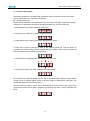
■ Selecting reference pulse mode
→input PULS
1CN-11
input reference pulse
→input /PULS
1CN-12
input reference pulse
→input SIGN
1CN-13
input reference sign
→input /SIGN
1CN-14
input reference sign
Use parameter “Pn008, Pn009” to select “reference pulse mode”
Parameter
Code
Comments
Unit
Range
Default
--
0~2
0
--
0~3
0
--
0~2
0
input pulse mode:
Pn008
--
[0]SIGN + pulse
[1]CW+CCW
[2]A+B(perpendicular × 4)
Reference pulse form
[0] does not invert PULSE
reference, does not invert
SIGN reference
[1] does not invert PULSE
Pn009
--
reference,
inverts SIGN
reference
[2] inverts PULSE reference,
does
not
invert
SIGN
reference
[3] inverts PULSE reference,
inverts SIGN reference
pulse input frequency selection
[0] when pulse is difference
input, servo receiving pulse
frequency≤500K
Pn058
--
[1] when pulse is difference
input, servo receiving pulse
frequency≤300K
[2] when pulse is difference
input, servo receiving pulse
frequency≤100K
- 23 -
EDC-E Series AC Servo User's Manual
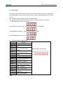
Following are available reference pulse styles, please make the setting according to
specification of host controller.
Pn008
Reference
servomotor forward run
style
reference
reference
PULS
(1CN-11)
PULS
(1CN-11)
Sign + pulse
0
servomotor reverse run
train
SIGN
(1CN-13)
“H”
PULS
(1CN-11)
“L”
SIGN
(1CN-13)
“L”
PULS
(1CN-11)
CW pulse +
1
CCW pulse
PULS
(1CN-11)
2 phase
2
SIGN
(1CN-13)
SIGN
(1CN-13)
perpendicular
pulse
“L”
PULS
(1CN-11)
90
0
SIGN
(1CN-13)
SIGN
(1CN-13)
900
User may select to invert input signal or not by setting Pn009 according to actual requirements.
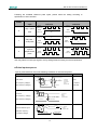
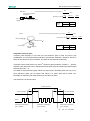
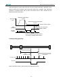
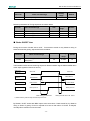
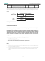
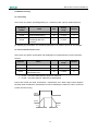
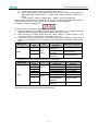
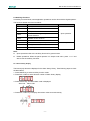
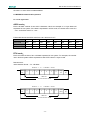
■ Pulse input sequence
Input of pulse reference must meet following conditions on level and sequence.
Pulse form
Electrical specification
SIGN
t1
t2
Remark
t7
t3
SIGN+PULS
PULS
t4
t5
t
Max. frequency: 500kpps
t6
T
(Open Collector :200kpps)
Forward reference
t1,t2=0.1µs
t3,t7=0.1µs
t4,t5,t6>3µs
t=1.0µs
(t /T)×100 = 50%
Reverse reference
t1
T
CW+CCW
Max. frequency:500kpps
CCW
t1,t2=0.1µs
t3>3µs
t=1.0µs
(t /T)×100 = 50%
t
t2
CW
t3
(Open Collector :200kpps)
Reverse reference
Forward reference
t1
t2
Phase A
90°phase different signal
t1,t2=0.1µs
t=1.0µs
(t /T)×100 = 50%
Phase B
t
(A+B) Max. frequency:
×4 multiplier :200kpps
T
Forward Instruction
Phase B is 90°forward
from phase A
- 24 -
Reverse Instruction
Phase B is 90°
behind phase A
SIGN
H=Forward
L=Reverse
EDC-E Series AC Servo User's Manual
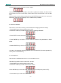
■ Clear error counter
Follow the steps below to clear "Error counter".
→input
CLR
1CN-7
Clear error counter input
When CLR signal is Low level, error counter is cleared.
Way to clear error counter:
- Servo drive's internal error counter is zero(0).
- This signal means "power level active", it's required to retain some time before the signal
takes effect. The signal has to be canceled after the pulse is cleared, otherwise, the counter is
always in the zero Clear status, which will result in no action in the servo position loop.
In position control mode, some pulses will remain in error counter when servo is OFF.
Therefore, the error counter has to be cleared immediately after servo is re-enabled. With
Pn005 setting, pulse signal of error counter can be cleared automatically when servo is OFF.
Parameter
Name and comments
No.
Setting range
Default
0~1
0
0:When S-OFF, clear error counter
Pn005
1:When S-OFF, does not clear
error counter
■ Position reference 1st filter time
position reference 1st filter can improve system's respond smoothness to given reference
pulse.
If reference input is comparatively rough, the dividing frequency multiplication is set too
large or frequency of pulse input is low, which can implement more smooth control of
servo system.
If position reference 1st filter time constant(that is Pn024)is set too large, servo system's
dynamic performance will be reduced.
Parameter
No.
Pn024
Name
position reference 1st
filter time constant
Unit
Setting range
Default
ms
0~1000
0
Unit
Setting range
Default
ms
0~1000
0
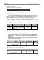
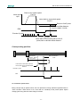
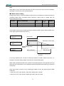
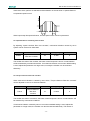
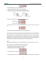
■ Position reference smoothing filter time
Par. No.
Pn033
Name
position reference smoothing
filter time constant
- 25 -
EDC-E Series AC Servo User's Manual
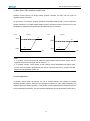
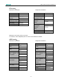
Different results between positioning after the change.
position reference 1st filter time
position reference smoothing filter time
(Pn024)
(Pn033)
Before smoothing
After smoothing
100%
100%
Before smoothing
After smoothing
63%
37%
t
Pn024
t
Pn033
Pn033
Step response waveform
Pn024
Step response waveform
Pn033
100%
Before smoothing
After smoothing
Pn033
Trapezoid reference response waveform
t
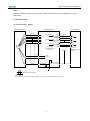
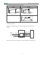
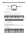
4.2.2 Encoder output signal
The servo drive outputs pulse signal from the encoder A/B/C, which is used with the host
controller.
Servo drive
2CN
Servo motor
Encoder
FG
Host controller
1CN
Linear drive output
Phase A
Phase A
Phase B
Phase B
Phase C
Phase C
Output circuit is bus drive output. Make circuit connection with reference to following circuit.
- 26 -
EDC-E Series AC Servo User's Manual
Host controller
EDC Servo drive
Line receiver
R
*
Encoder A
Encoder B
Encoder C
2-8
PAO
2-18
/PAO
2-9
PBO
2-19
/PBO
2-10
PCO
2-20
/PCO
P
R
P
R
P
Linear drive output
equivalent with
AM26LS31
Connector Shell
*
P
Represent multi-twisted cable
R=220? ~470?
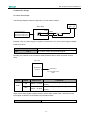
■ Output signal
Output encoder signal after frequency is divided.
Output → PAO
1CN- 8
A phase pulse differential Output
Output → /PAO 1CN- 18
Output → PBO
1CN- 9
B phase pulse differential Output
Output → /PBO 1CN- 19
Output → PCO 1CN- 10
C phase pulse differential Output
Output → /PCO 1CN- 20
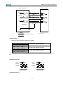
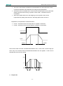
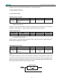
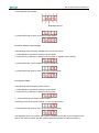
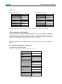
The following illustration shows the style of perpendicular pulse output of Phase A and Phase
B.
Parameter Pn011=0:
CCW
CW
90°
Phase A
Phase A
Phase B
Phase B
90°
t
t
Parameter Pn011=1:
- 27 -
EDC-E Series AC Servo User's Manual
CW
CCW
90°
90°
Phase A
Phase A
Phase B
Phase B
t
t
■ Set pulse dividing frequency ratio
Set pulse dividing frequency ratio with following parameters.
Parameter
Meaning
Set PG dividing
Pn010
frequency ratio
Unit
Range
Default
2500P/R
1~2500
2500
0~1
0
Inverts dividing
Pn011
frequency output
phase
Set output pulse numbers of PG output signal(PAO,/PAO,PBO,/PBO)which is transmitted
outward subject to servomotor running for one revolution.
Servo drive
Linear drive output
2CN
Servo motor encoder
PG
1CN
Phase A(1CN-8,1CN-18)
Phase A
Phase B
Phase C
Frequency
Dividing
Output
Phase B(1CN-9,1CN-19)
Phase C(1CN-10,1CN-20)
Divides pulse frequency of servomotor encoder(PG) and output according to pulse number
setting.
Setting value means the individual output of pulse numbers for PAO, /PAO, PBO and /PBO
signal when servomotor runs for one revolution. If Pn010 is set as 1000, it means output of
PAO signal is 1000 pulses subject to motor runs for one revolution, so do the /PAO, PBO and
/PBO signal output.
Please make setting according to the machine and reference the units of the controller.
Note: After parameter changes, turn power OFF and then turn power ON again.
- 28 -
EDC-E Series AC Servo User's Manual
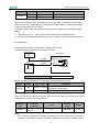
4.2.3 Sequence I/O signal
To control sequence input and output signal of the servo drive's, please connect according to
your application requirements.
■ Connect sequence input signal
Following illustration shows how to connect the sequence input signal.
EDC Servo drive
+24VIN
16
+
-
3.3K
S-ON
ALM-RST
CLR
ZPS
15
6
7
17
Notes:
24V I/O power supply is required, since there is no internal power supply servo drive.
External power supply specification: DC24V±1V, 500mA higher.
It's suggested that input circuit and output circuit use the same power supply.
Voltage range of input circuit is +11V~+25V. If power voltage is low and relays are used , low
value current switches or relay are required to avoid bad contact. Always check and confirm
the electrical specification of the relay or relevant parts before use.
input +24VIN 1CN- 16
External I/O power input
■ Connect contact point of output signal
- 29 -
EDC-E Series AC Servo User's Manual
IO
Power supply
Servo drive
+24V
1CN
2
Pn049= 0:BK 1:COIN 2:CLT
3:S-RDY 4:C-Pulse
3
Pn050=0:BK 1:COIN 2:CLT
3:S-RDY 4:C-Pulse
Optocoupler output (each
output node)
Max. output voltage:30V
Max. output current:50mA
0V
ALM
4
5
■ Handling of I/O signals
Input signals are smoothed with filters to the servo drive. Set filter time with parameter Pn053.
Active power level of input signal is controlled by Pn054, and active power level of output
signal is controlled by Pn055.
Following signals are I/O signals subject to default parameters.
Para.
Name and meaning
no.
Unit
Setting range
Default
Pn053
input signal filter time
ms
0~1000
100
Pn054
Inverts input signal
-
0~15
0
Pn055
Inverts output signal
-
0~7
0
During filter time of input signal, if signal spikes occur, input signal will not be received by servo
drive. Input signal will be received by the drive only after it keeps stable for the set time, that is,
signal need to keep on a constant level within period of Pn053 before it can be accepted by the
servo drive. Drive estimates signal validity according to Pn054.
Following table shows operations to invert input signal(Pn054).
Digit
BIT3
BIT2
BIT1
BIT0
input signal
ZPS
CLR
ALM-RST
S-ON
Signal level
H
L
H
L
H
L
H
L
Pn054
0
1
0
1
0
1
0
1
0
1
0
1
0
1
0
1
Signal active
N
Y
Y
N
N
Y
Y
N
N
Y
Y
N
N
Y
Y
N
In above table,
"H": it means input signal is at high level.
"L": input signal is at low level.
"0": setting value in Pn054. "0" means input signal low is active.
"1": setting value in Pn054. "1" means input signal high is active.
“N”:input signal is inactive.
- 30 -
EDC-E Series AC Servo User's Manual
“Y”:input signal is active.
For example: if CLR is set high and all other signals are set at a low level are to become active,
then it is expressed as 000100 in a binary system, it will be 4 if converted into decimal system,
that is, Pn054 must be set as 4.
Take similar operation steps to set Output signal.
Digit
Output
Meaning
Signal
Release
meaning
braking
Pn055
Output
Level
BIT2
BIT1
BIT0
BRK
COIN
ALM
braking
arrive
Not arrive
alarm
No alarm
0
1
0
1
0
1
0
1
0
1
0
1
low
high
high
low
low
high
high
low
high
low
low
high
Note: When ALM is in normal status, Output level is high, inverts other two signals.
For example:
If output level is required to meet following conditions:
- high when braking signal releases braking
- low when COIN signal is active
- ALM output is high when alarm occurs
then it will be expressed as 100 in binary system, if it is converted into decimal system it would
be 4, that is, Pn055 should be set as 4.
Note:
·The validity of I/O signals mentioned in this manual are referring to a normal situation, that is,
active when input signal is at low level, active when BK、COIN output is at low level, ALM
output is at high level.
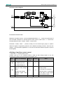
4.2.4 Electronic gear
With “Electronic gear” function, the workpiece travel which is equivalent to input reference
pulse can be set to any value. The Host controller sends a reference pulse that can implement
control operation with no consideration in mechanical gear ratio and output pulses of the
encoder, so the control calculation becomes easier.
Without electrical gear
With electrical gear
Workpiece
Workpiece
Reference unit:1µm
Encoder pulse:
2500
Encoder pulse:
2500
Ball screw pitch:6mm
Need to move distance 10mm
Due to once rotate 6mm
10÷6=1.6666 rotations
2500×4 pulse generated by one rotaion
1.6666×2500×4=16666 pulse
Reference input 16666 pulse
The calculate must be done at the upper
device。
Ball screw pitch:6mm
Previously identify mechanical condition, reference
unit with electrical gear
- 31 -
Need to move distance 10mm
Reference unit is 1µm,so
10mm/1µm=10000 pulse
EDC-E Series AC Servo User's Manual
■ Setting the electronic gear function
Take following steps to calculate electronic gear ratio(B/A), its value is set in Pn022 and
Pn023 of the user parameter.
1. Mechanical forms relates to electronic gear
·gear ratio
·ball bearing screw pitch
·pulley radius
2. Encoder pulses of servo motor
3. Equivalent pulse (reference unit )
Reference unit refers to the unit of minimum move distance required by load or the minimum
Reference move the workpiece by 0.001mm unit
Reference unit:0.001mm
Please decide the reference unit by mechanical form and position precision
reference unit of the host controller.
For example, reference unit can be 0.01mm, 0.001mm, 0.1°, 0.01 inch, reference of input one
pulse, the distance or angle of pulse equivalent.
If pulse is equivalent to 1um, input reference pulse 50000, then the move distance will be
50000×1um=50mm
4. With pulse equivalent, load move distance is calculated subject to load shaft turning for one
revolution.
Movie distance of load (reference unit)= Moving distance of load / pulse equivalent.
If ball bearing screw pitch is 5mm, pulse equivalent is 0.001mm,
5mm/0.001mm = 5000(reference unit)
Ball screw
Rotation table
Belt pulley
Bearing shaft
P
pD
Ball screw
Bearing shaft
D:Belt roller diameter
P:Pitch
1 rotation=
P
Reference unit
1 rotation=
360º
Reference unit
- 32 -
pD
1 rotation=
Reference unit
EDC-E Series AC Servo User's Manual
5. Example for electronic gear ratio(B/A)
Gear ratio of motor shaft and load shaft is n/m. (Motor revolves for m revolutions, load shaft
revolves for n revolutions.)
Electronic gear ratio(B/A)= [( encoder pulse number × 4) / moving distance when load shaft
finishes one revolution ] ×(m/n)
It is suggested that the electronic gear is set within the following range:
0.01≤electronic gear ratio(B/A)≤100
6. Set parameter
To make reduction of(B/A) to get A and B, and select the most proximal whole number which
is lower than 32767.
Thus, setting of electronic gear ratio is completed.
Par.NO.
Pn022
Pn023
Name
electronic gear B
(numerator)
electronic gear A
(denominator)
Unit
Range
Default
--
1~32767
1
--
1~32767
1
Electronic gear ratio(B/A)= Pn022 / Pn023
·B =“Encoder pulse number × 4”דrotation speed of motor shaft”
·A = reference pulse number of each unit ( load movement when load shaft finishes one
revolution ) ד rotation speed of load shaft
■ Example of an electronic gear
The following illustrations show the settings for different mechanical structures.
Belt + Pulley
3.14×100mm
Reference unit:0.2mm
Load movement amount of bearing shaft ’s one round rotation=
=15700
0.2mm
()
Bearing shaft
B
Electrical gear ratio=
Redution ratio:
2:1
=
A
=
2500×4×2
15700×1
200
157
Pulley diameter :100mm
Setting
value
Incremental encoder:2500P/R
- 33 -
Pn022
200
Pn023
157
Pn022
=
Pn023
EDC-E Series AC Servo User's Manual
6mm
Ball screw
Load movement amount of bearing shaft one round rotation=
=6000
0.001mm
Reference unit:0.001mm
Bearing shaft
()
B
=
Electrical gear ratio=
A
Incremental encoder
2500P/R
2500×4×1
=
Pn022
Pn023
6000
Ball screw pitch:6mm
Setting
value
Platform
Pn022
5
Pn023
3
Load movement amount of bearing shaft one round rotaion=
360º
=3600
0.1º
()
Electrical gear ratio=
Reference unit :0.1o
B
A
= 2500×4×3
3600
Reduction ratio 3:1
Setting
value
Bearing shaft
Incremental encoder
2500P/R
Pn022
75
Pn023
9
■ Dynamic electronic gear
If system pulse frequency is low and only one electronic gear is used, it's hard to give
consideration to use both processing efficiency and position resolution. Therefore, the servo
has a second electronic gear numerator, and both can be switched dynamically.
In position control mode (Pn041=0), after 2nd electronic gear is enabled(Pn056=1), dynamic
electronic gear becomes active. Switching electronic gear requires PCON signal (input signal
select Pn051's bit1=1).
It is better to switch electronic gear without any pulse input, otherwise pulse loss may occur.
Since electronic gears will not switch until there is no pulse input that is within 1ms.
Numerator of electronic gear after switching is the value of Pn056.
The sequence is as shown below.
PCON effective
t1
t2
t3
PCON disable
t4
PCON disable
Pulse
Molecule of electrical
gear=Pn022
Molecule of electrical
gear=Pn056
Molecule of electrical
gear=Pn022
t1、t2、t3、t4>1ms
- 34 -
=
Pn022
Pn023
EDC-E Series AC Servo User's Manual
■ Position control diagram
Servo drive( position control)
Forward
feedback gain
Pn017
Speed offset
Forward
feedback filter
Pn025
Pn016
COIN signal
Pulse
reference
Direction
Input mode
Pn008
Position
reference
filtering
Pn024
numerator
Pn022
Pn023
denominator
+
-
Positional
deviation
counter
+
Position loop
Pn015
+
Servo motor
Speed adjustor
+
+
-
Gain Pn013
M
Current loop
Intergrator
Pn014
Speed inspection filter
Pn028
Speed
inspection
AB
Phase
4 times
frequency
C phase
Pulse output
PG
Encoder
4.2.5 Position contact control
Reference of position control(control modeparameterPn041=0) comes from pulse input of
host controller. Reference of internal speed control (control mode Pn041=1)comes from
internal parameter value(Pn080~Pn095)of servo drive.
Parameter(Pn080, Pn081)~(Pn094, Pn095) are the internal eight groups of position
reference register. Programming method can be defined according to Pn070. There are two
method: (a) incremental; (b)absolute. It can also be used with external I/O(1CN-7 input as
PCON signal).
■ Setting of position contact control
1. Set Pn041=1(internal speed control);
2.Select cycle run or not, whether PCON is used as step change signal or not, the
programming method, start and stop point of program, etc.
Para.
Name and meanings
No.
Setting
Default
Other
range
Select cycle run
Pn068
[0] multiple cycle run
0
0~1
[1] multiple single run
Enable/Disable
PCON
When PCON signal is used
signal as step change
Pn069
signal
[0] delay step change
[1]PCON
signal
as step change:
0
0~1
step
Programming method
2.PCON active is generated
at the edge of input signal
change
Pn070
1. Set Pn051 or Pn052 as 2
from inactive to active.
0
0~1
- 35 -
EDC-E Series AC Servo User's Manual
[0] incremental
[1] absolute
Which of the 8 groups of
Pn072
Start point of program
0
0~7
position data is used as start
point.
Which of the 8 groups of
Pn073
Stop point of program
1
0~7
position data is used as stop
point.
3. Required moving distance of motor is calculated according to actual moving
distance, then moving distance data is filled in each contact position register.
Para. No
Pn080
Name and meanings
move distance 0 revolution
Unit
Setting range
Default
10 4 reference
-32767~32767
1
1reference pulse
-9999~9999
0
10 4 reference
-32767~32767
2
1reference pulse
-9999~9999
0
10 4 reference
-32767~32767
3
1reference pulse
-9999~9999
0
10 4 reference
-32767~32767
4
1reference pulse
-9999~9999
0
10 4 reference
-32767~32767
5
1reference pulse
-9999~9999
0
10 4 reference
-32767~32767
6
1reference pulse
-9999~9999
0
10 4 reference
-32767~32767
7
1reference pulse
-9999~9999
0
10 4 reference
-32767~32767
8
-9999~9999
0
pulse
Pn081
Pn082
move distance 0
move distance 1 revolution
pulse
Pn083
Move distance 1 low
Pn084
Move distance 2 revolutions
pulse
Pn085
Move distance 2 low
Pn086
Move distance 3 revolutions
pulse
Pn087
move distance 3 low
Pn088
move distance 4 revolutions
pulse
Pn089
move distance 4 low
Pn090
move distance 5 revolutions
pulse
Pn091
move distance 5 low
Pn092
Move distance 6 revolutions
pulse
Pn093
Move distance 6 low
Pn094
Move distance 7 revolutions
pulse
Pn095
moving distance 7 low
1reference pulse
- 36 -
EDC-E Series AC Servo User's Manual
Set parameters such as run speed, acceleration/deceleration time, stop time, and so on
according to field working situation.
Para. No.
Name and meanings
Unit
Setting range
Default
Pn096
Move distance 0 speed
r/min
0~3000
500
Pn097
move distance 1 speed
r/min
0~3000
500
Pn098
Move distance 2 speed
r/min
0~3000
500
Pn099
move distance 3 speed
r/min
0~3000
500
Pn100
move distance 4 speed
r/min
0~3000
500
Pn101
move distance 5 speed
r/min
0~3000
500
Pn102
move distance 6 speed
r/min
0~3000
500
Pn103
Move distance 7 speed
r/min
0~3000
500
ms
0~1000
0
ms
0~1000
0
ms
0~1000
0
ms
0~1000
0
ms
0~1000
0
ms
0~1000
0
ms
0~1000
0
ms
0~1000
0
move
Pn104
distance
0
first(1st)
acceleration/deceleration time
constant
move
Pn105
distance
1
first(1st)
acceleration/deceleration time
constant
move
Pn106
distance
2
first(1st)
acceleration/deceleration time
constant
move
Pn107
distance
3
first(1st)
acceleration/deceleration time
constant
move
Pn108
distance
4
first(1st)
acceleration/deceleration time
constant
move
Pn109
distance
5
first(1st)
acceleration/deceleration time
constant
move
Pn110
distance
6
first(1st)
acceleration/deceleration time
constant
move
Pn111
distance
7
first(1st)
acceleration/deceleration time
constant
Pn112
Move distance 0 stop time
50ms
0~32767
10
Pn113
Move distance 1 stop time
50ms
0~32767
10
Pn114
Move distance 2 stop time
50ms
0~32767
10
Pn115
Move distance 3 stop time
50ms
0~32767
10
Pn116
Move distance 4 stop time
50ms
0~32767
10
Pn117
Move distance 5 stop time
50ms
0~32767
10
Pn118
Move distance 6 stop time
50ms
0~32767
10
Pn119
Move distance 7 stop time
50ms
0~32767
10
- 37 -
EDC-E Series AC Servo User's Manual
4. After Servo ON, position contact runs.
Position contact control is a single contact position controller, the user can use cycle run
operation with this function.
As for Pn070, for example, position reference P0(Pn080×10000+Pn081) is ten revolutions,
position reference P1(Pn082×10000+Pn083)is thirty revolutions, when running from P1 to P2,
the difference between incremental type and absolute type is as below:
Pn070=0
pulse
pulse
Pn070=1
P2
400000
P2
300000
P1
P1
100000
100000
Time
Time
Note:
1. In position contact control mode, electronic gear function does not work, which can be
regarded as the electronic gear ratio is always 1:1.
2. In position contact control mode, all the position control parameters will affect motor
running, such as position proportional gain Pn015, feed forward Pn017, position first filter
Pn024, feed forward filter Pn025, etc.
4.2.6 Zero adjustment
In position control mode, servomotor can run to a fixed position, this position is normally
regarded as Zero position. After the host controller is switched on, zero position adjustment is
required before processing operation. This position will be regarded as the reference point for
every subsequent movement. The zero position adjustment can be done with the servo drive.
- 38 -
EDC-E Series AC Servo User's Manual
■ Parameter setting for zero adjustment
1. Select zero adjustment according to the application.
Para. no.
Name and meanings
Unit
Setting
range
Default
Return method of origin
Z
Y
X
Z=0:disable origin return function
Z=1:origin return starts automatically only
after first S-ON
Z=2:origin return starts automatically every
Pn071
time S-ON
Y=0 : search Pulse C after origin has
—
0~211
0
returned
Y=1:does not search Pulse C after origin
has returned
X=0: origin returns at forward run direction
X=1:origin returns at reverse run direction
2. Setting zero adjustment speed
Para. No.
Pn074
Pn075
Name and meanings
Speed 1 during reference searching(hit position
limit switch)
Speed 3 during reference searching(after
releasing position limit switch)
Pn077
Origin return offset revolution
Pn078
Origin return offset pulse number
Unit
setting
range
Default
r/min
0~3000
1000
r/min
0~3000
5
9999
0
9999
0
10000
pulse
1 pulse
3. Comments
When zero adjustment method is selected according to practical requirements (set Pn071),
zero adjustment will be implemented according to this setting.
When zero adjustment is made, the servomotor will run at the set speed of Pn074.
When ZPS(1CN-17) signal is active, if the parameter setting requires the servo motor to return
and search Pulse C, then motor will run reverse at the set speed of Pn075, otherwise, motor
will run forward at the set speed of Pn075.
- 39 -
EDC-E Series AC Servo User's Manual
When ZPS signal is inactive, after first Pulse of motor encoder is detected, calculation of zero
balance offset pulse is started, motor stops after offset pulse completes. Zero adjustment
operation is completed. Motor will not return and search Pulse C after it detects the zero
adjustment position limit switch.
Motor speed
(rpm)
Back zero switch speed
(Pn074)
Leave back to zero switch speed
(Pn075)
No return to search Z pulse
/ZPS
(zero signal)
Offset distance of back to zero
(Pn077×10000+Pn078)
Encoder
C pulse
Leave back to zero swith,after the first C
pulse,start to calculate offset distance
Corresponding position:
Mechanical movement ,
no return to find C pulse
Leave back to zero switch ,after
the first C pulse start to calculate
offset distance
Motor
deceleration
Encoder C pulse
ZPS signal
Return and search Pulse C after reaching zero adjustment switch:
- 40 -
EDC-E Series AC Servo User's Manual
Motor speed
(rpm)
Back to zero switch speed
(Pn074)
Leave back to zero switch speed
(Pn075)
Return to find Z pulse
Back to zero offset distance
(Pn077×10000+Pn078)
/ZPS
Encoder C pulse
Leave back to zero switch,after the first C
pulse,start to calculate offset distance.
Corresponding position:
Mechanical
movement,back to
find C pulse
Motor deceleration,
CCW
Leave back to zero switch ,after the
first C pulse ,start to calculate offset
distance
Encoder C pulse
ZPS
4.2.7 Parameter speed control
Being a simple way of speed control, user can preset the running speed as regulated value in
"User Constant". When Servo is On, motor will run constantly at the preset speed. Speed
change goes along with the value change in Pn048.
- 41 -
EDC-E Series AC Servo User's Manual
Servo drive
S-ON
1CN-15
Motor run at the speed
set in the parameter
M
Pn048
■ Set parameter speed
When using “parameter speed control”, take following steps to make the setting.
1. Set Pn041 properly to enable internal speed selection function.
Para. No.
Name
Setting range
Default
0~2
0
Control mode
Pn041
selection
Application cases
Position control and speed
control
In internal speed control mode, set Pn041 to 2.
Pn041
Comments
2
Run at regulated speed of Pn048
Note:
1:OFF(input signal is inactive)
0:ON(input signal is active)
2. Set Pn048 to wanted speed value
Value of Pn048 can be changed manually or via communication, to make motor run at
specified speed. If the speed is set over maximum rotation speed, then motor will run at
maximum speed instead.
3. Set "soft start time"
Para. NO.
Name
Unit
Setting range
Default
Pn019
Soft start acceleration time
ms
0~10000
100
Pn020
Soft start deceleration time
ms
0~10000
100
ms
0~1000
0
Pn021
S shape acceleration
/deceleration time
- 42 -
EDC-E Series AC Servo User's Manual
Servo drive sets internal acceleration and deceleration time and implements control
of speed acceleration and deceleration according to these parameters
Soft start function is available when control mode is internal speed control, parameter
speed control and JOG running. In position control mode,soft start function is
unavailable.
When input speed reference is stair stepping, smooth speed control can be
implemented by setting "Soft start time". Normally speed control is set to 0.
Explanation of the parameter is described below:
Pn019:the period of time from stop status to a speed of 1000r/min
Pn020:the period of time from the speed of 1000r/min to stop status
Speed reference
Speed
Pn019
Pn020
Pn019 and Pn020 are linear acceleration/deceleration time. In the event of rather large jolt
which may occur because linear acceleration/deceleration time are applied, Pn021 can be
selected and set to smooth running.
Speed
Pn021
Pn021
Pn019
Pn021
Pn021
Pn020
4. Torque limit
- 43 -
EDC-E Series AC Servo User's Manual
Setting Pn026 and Pn027 to limit torque is available in any control mode.
Para.NO.
Function
Unit
Setting range
Default
Pn026
forward run torque limit
1%
0~300
250
Pn027
reverse run torque limit
1%
0~300
250
Note: System response may be slowed down if torque limit is set to an undersized value.
4.3 Servo drive settings
4.3.1 JOG speed
JOG speed control is enabled with PC communication or hand held operator.
Set JOG speed with Pn032.
Para. No.
Pn032
Name and meanings
JOG speed
Unit
r/min
setting range
0~3000
Default
500
Note:
No matter what value Pn041 is, or whether /S-ON is active or not, JOG running is
always possible on the condition that cable connection of servomotor is correct and servo
drive has no problem.
During JOG running, servo drive will ignore host controller's control signal and status of
limit switch and property loss is easily caused due to improper operation. Therefore, JOG
must be prohibited during normal production.
4.3.2 Control mode selection
Control modes can be selected with parameter Pn041 as described below.
Para. No.
Pn041
Description
[0]position control
[1]internal speed control
[2]reference speed control
Range
0~2
Default
0
■ General information of above control methods are introduced as follows:
[0] position control( pulse train reference)
Servo drive accepts pulse train generated by host controller and speed and positioning are
behaving according to host control's demand.
[1] position contact control(internal position reference)
Enable speed control by contact reference. Please refer to 4.2.7“internal speed control” of the
manual.
[2] parameter speed control(parameter reference)
Run at constant speed as specified in Pn048.
- 44 -
EDC-E Series AC Servo User's Manual
The following table shows the meaning of some input signals in different modes.
Pn041
Control mode
Servo drive
0
position control( pulse train reference)
Normally, position control input reference
refers to pulse train.
1
Internal position control ( internal position
reference)
No external input signal is required. Run
according to value in internal position
register.
2
parameter speed control(parameter
reference)
Servo motor rotates according to speed and
status specified in Pn048 setting.
PULS
Position
reference SIGN
1CN-11
1CN-12
1CN-13
1CN-14
4.4 Stop function settings
4.4.1 Dynamic brake
Set the value of Pn004 to select stop mode of servo motor: DB braking or coast stop.
If dynamic brake is not used, motor stops naturally, with no brake, by using the friction
resistance of the motor in operation.
Para. No.
Pn004
Function
Range
Stop mode of servomotor when servo OFF or
alarm occurs.
Para. No.
0~3
Default
0
Description
[0] When servo OFF or alarm occurs, DB braking active
[1] When servo OFF or alarm occurs, coasts to a stop.
Pn004
[2] When servo OFF or alarm occurs, DB braking active and is released
after motor stops
[3] When servo OFF or alarm occurs, coasts to a stop, DB active after
motor stops
- 45 -
EDC-E Series AC Servo User's Manual
In following situation, the servo drive will switch off the supply to the servomotor.
When /S-ON(1CN-15)signal is OFF
When servo alarm occurs
When power supply is OFF
Note:
Dynamic brake(DB) forces servomotor to stop immediately upon emergency, therefore,
following notes must be considered.
Do not start/stop servomotor frequently with power On/OFF switch, this will cause fast
aging and reduced performance of the internal elements in the servo drive.
Do not start/stop servomotor frequently with /S-ON(1CN-15), otherwise built-in energy
consumption resistor is damaged easily .
“Dynamic brake(DB)” is one way to force servomotor to stop immediately upon emergency.
By shorting power cable of servo motor to achieve emergency stop of servo motor. This circuit
is already built in EDC servo drive.
Servo motor
Servo drive
4.4.2 Holding brake
Servo motor with brake active (Holding brake) is required on the condition that perpendicular
axis(the axis which withstands external force) is used, to prevent non-electrified servo motor
from turning due to the action of gravity.
Vertical axis
Forced axis
Servo motor
Hold brake
Servo motor
Outside force
Prevent from
movement by gravity
when power-off
Prevent from
movement by force
- 46 -
EDC-E Series AC Servo User's Manual
The action of brake holding is controlled by servomotor's brake interlock output signal (/BRK).
Make sure servomotor is mechanically separated before confirming action of servomotor and
brake active (holding brake) . If all the parts are moving well, connect servo motor to the
machine.
■ Connection example
/BRK controls Power On/Off of brake sticking, which consists of the control circuit of holding
Servo drive
Power supply
Servo motor
with brake
U
V
W
FG
U
V
W
E
R
T
2
3
4
1
Motor
M
E
BRK-RY
+24V
/BRK
+24V
6
0V
7
COM
BK
Encoder
P
G
2CN
BRK-RY
+24V
AC
DC
0V
brake. The illustration below shows a typical connection example.
BRK-RY:brake sticking control relay
→ Output /BRK
Brake interlock output
Speed control, position control
/BRK is used to control the status of brake sticking. When brake active is not used, this
connection is not required.
ON:“L” level
Release brake
OFF:“H” level
Start brake
Note:
If power peak occurs, servo drive will give no output of /BRK signal, and periphery circuit
decides the status of brake hold, which has to be considered when designing and control
circuit.
When using /BRK signal, set output with following parameters.
Para. No.
Name and meanings
Setting
range
Default
Pn049
output signal1CN-2 pin definition
0~4
0
Pn050
output signal1CN-3 pin definition
0~4
1
- 47 -
EDC-E Series AC Servo User's Manual
Para. No.
Pn055
Setting
Name and meanings
Default
range
Inverts output signal
0~7
0
Relevant parameters to Timing sequence are shown below.
Para. No.
Setting
Name and meanings
unit
Default
Pn044
Basic waiting flow
ms
0~5000
10
Pn045
brake waiting speed
R/min
10~500
100
Pn046
brake waiting time
ms
10~1000
500
range
■ Brake ON/OFF time
During the moment of brake active on/off , if servomotor travels for any distance owing to
external forces like gravity, adjust with Pn044 as below.
Para. No.
Pn044
Unit
Name and meanings
setting
Default
range
Basic waiting flow(Servo OFF
ms
delay time)
0~5000
10
The illustration below shows the timing sequence relation between signal /SON and BRK when
motor stops (speed is lower than 30 r/m.)
SON input
(1CN-15)
BRK output
(1CN-2)
Servo ON
Servo ON
Servo OFF
BRK disable
BRK effective
BRK effective
t2
t1
Brake status
Brake release
Motor status
Motor power on
Brake release
Braking
Motor power off
Basic waiting process Pn044
Motor power on
Waiting time after Servo ON Pn043
t1,t2:determined by external relay and brake loop move time
By Default, /S-OFF works with /BRK output at the same time. If load travels for tiny distance
owing to action of gravity, Pn044 is required to be set so that action of /S-OFF is delayed,
normally this movement can be removed.
- 48 -
EDC-E Series AC Servo User's Manual
Note:
When alarm occurs, servo drive will switch off main circuit loop of servo motor immediately,
meanwhile, machine may move a small distance.
■ Brake active setting
During motor running, movement setting of brake active is controlled by Pn045 and Pn046. By
controlling brake active movement timing sequence, brake active is started after the
servomotor stops running.
Para. No.
Name and meanings
Pn045
Brake waiting speed
Pn046
Brake waiting time
setting
Unit
range
Default
r/min
10~500
100
ms
10~1000
500
The illustration below shows the timing sequence relation between signal /SON and BRK when
motor stops (speed is higher than 30 r/m.)
SON input or Alarm
(1CN-15)
Servo ON
Servo OFF
DB stop or free stop
Motor speed
(r/min)
Brake waiting time
Pn045
BRKoutput
(1CN-2)
BRK effective
BRK disable
Brake waiting time
Pn046
For running a brake motor, if S-OFF is caused by variation of /S-ON or alarm occurrence , it's
required to set brake waiting speed of servomotor or brake waiting time.
Brake waiting time(Pn046) refers to the period of time delay between motor stops(/S-OFF) and
brake active is implemented. This parameter should be adjusted while observing mechanical
movements..
When servo motor is running, if any of following conditions is true, the output signal of /BRK
will be ON.
1: After servo OFF, motor speed is lower than setting value of Pn045.
2: After servo OFF, motor speed is higher than setting value of Pn046.
- 49 -
EDC-E Series AC Servo User's Manual
4.5 Protection design
4.5.1 Servo alarm output
The following diagram shows the right way to connect Alarm Output.
IO
Power supply
+24V
Servo drive
1CN
4
5
Optocoupler output
(Each output node)
Max.output voltage: 30V
Max.output current: 50mA
0V
ALM
COM
External +24V I/O power supply is required, since there is no +24V power supply available
inside servo drive.
Output → ALM 1CN- 4
Servo alarm output
COM
Servo alarm output uses grounding signal
1CN- 5
Normally, the external circuit consists of /ALM should be able to switch off power of servo
drive.
Servo drive
Be detected
abnormal
ALM Output
Cut off the main circuit
power
Signal
Status
Output level
ON
1CN-4:“L” level
OFF
1CN-4:“H” level
ALM
Comments
Normal state (output signal is high when alarm
occurs)
Alarm state (output signal is high when alarm
occurs)
When “servo alarm (ALM)” happens, always remove alarm reasons first , and then turn the
input signal "ALM-RST" to ON position to reset alarm status.
→ input
ALM-RST 1CN- 6
alarm reset input
- 50 -
EDC-E Series AC Servo User's Manual
Signal
Status
Input level
ON
1CN-6:“L” level
Reset servo alarm
OFF
1CN-6:“H” level
Does not reset servo alarm
ALM-RST
Comments
Normally, the external circuit can switch off power supply of servo drive when alarm occurs.
When servo drive is re-switched on, it removes alarm automatically, so normally alarm reset
signal is not required to be connected.
In addition, reading alarm information and alarm reset are enabled with hand-held operator.
Note:
When alarm occurs, always remove alarm reasons before resetting alarms.
Only alarms with alarm number being 3,4,13,14,15 and 21 can be removed by /ALM-RST.
4.5.2 /S-ON input
Host controller is used to control enable or disable servo system.
Following illustration shows the way to connect /S-ON.
Power supply
IO
Servo drive
+ 24V
Host
+24VIN
1CN-16
/S-ON
1CN-15
3.3K
Optocoupler
0V
→ input /S-ON 1CN- 15
Servo On(ON)
Switch servomotor between Power on and Power of,when low level is active.
Signal
/S-ON
Status
Input level
ON
1CN-15:“L” level
OFF
1CN-15:“H” level
Comments
Servo ON, servo is energized(run servomotor
according to input signal)
Servo OFF, servo is not energized(can't run)
Pn043 is used to set waiting time during Servo On, which means the period of time from
internal relay's action to motor electrification.
Parameter
Name and
No
meanings
Pn043
Waiting time when
servo On
Unit
ms
Setting
range
20~2000
Default
200
Note:
It's not good to start/stop servomotor frequently with “/S-ON” signal. Always use input
reference to complete response operation, otherwise servo motor's lifetime will be
- 51 -
EDC-E Series AC Servo User's Manual
shortened.
When “/S-ON” high is active, if external cable is disconnected, input signal is high, /S-ON
will keep active.
During deceleration of Servo OFF, /S-ON signal is accepted only when motor speed is
lower than 30r/m.
Switch "Enable/Disable" Servo On input signal with the following parameter.
Para. No.
Name and meanings
Unit
Setting range
Default
—
0~1
0
[0] Enable Servo ON input signal
(/S-ON)
(Decided by 1CN-15 signal)
[1] Disable Servo ON input signal
Pn000
(/S-ON)
(Internal Servo ON, normally is Servo
ON, which is equivalent to 1CN-15
being active.)
4.5.3 Positioning complete output
Positioning complete“/COIN” signal: output after positioning completes.
Make connection according to the following diagram.
IO
Power supply
+24V 0V
Servo drive
1CN
Optocoupler output
(Each output node)
Max.output voltage: 30V
Max.output current: 50mA
Output → /COIN
Output → COM
3
5
COIN
COM
Positioning complete
Output
Positioning complete
Output grounding signal
position control
position control
Host controller can judge if servo action is completed or not with /COIN.
- 52 -
EDC-E Series AC Servo User's Manual
Speed
Reference speed
Motor speed
Offset
pulse
Pn030
Un012
Un013
0
/COIN
Un012:error pulse counter low position monitoring
Un013:error pulse counter high position monitoring
When output is active at low level:
ON status
COIN: “L” level
OFF status
COIN: “H” level
Positioning has completed. (Position offset is lower
than setting of Pn030.)
Positioning is not completed. (Position offset is lower
than setting of Pn030.)
Set "In position error" to control output time of /COIN.
Para. No.
Pn030
setting
Function
Unit
In position
reference
error
unit
range
Default
0~500
10
Using
method
position
control
Setting of In position error will not affect final accuracy of positioning.
By default, 1CN-3 is used as Positioning complete signal "/COIN" in position control mode,
while in speed control mode it's used as the speed coincidence output "V-CMP".
4.5.4 Speed reached output
Speed coincidence Output(/V-CMP)signal: photocoupler output signal, referring to output is
given when rotation speed of servo motor is the same as reference speed. It can be used as
the base of host controller's judgment. Connect and use this signal according to the following
IO
Power supply
0V
+24V
Servo drive
1CN
Optocoupler output
(Each output node)
Max.output voltage: 30V
Max.output current: 50mA
3
5
- 53 -
V-CMP
COM
EDC-E Series AC Servo User's Manual
diagram:
Output → /V-CMP+
speed coincidence output
Speed control
speed coincidence output
COM
Speed control
grounding signal
It refers to output signal of input speed reference and speed coincidence of actual motor
rotation.
When output status at low is active:
ON status
Speed coincidence( speed error is
/V-CMP+ “L” level
under setting value)
Speed coincidence fail( speed error
OFF status /V-CMP+ “H” level
is over setting value)
Pn029
Motor rolling speed
Reference speed
In this range output“V-CMP”
With the user's constant as below, the range of output /V-CMP can be designated.
Parameter
Function
number
Pn029
Speed coincidence
error
Unit
r/min
setting
range
0~100
Default
10
Control
method
Speed
control
When difference between speed reference and actual motor speed is under setting value,
output "/V-CMP" signal.
4.5.5 Handling instant power cut
Select if alarm output is made or not upon a sudden power interruption.
Parameter
number
Name and Description
Unit
setting range
Default
Select operations to be made upon
Pn003
—
power interruption
[0] gives no output of servo alarm
- 54 -
0~1
0
EDC-E Series AC Servo User's Manual
signal(ALM)
[1] Output servo alarm signal(ALM)
If power supply of servo drive is interrupted suddenly over 20ms and detected by servo drive.
Servo drive will decide if /S-ON and output servo alarm are required according to the value of
Pn003
220V
Power voltage
Instantaneous power off happen
Pn003=0
ALM
1CN-4
Pn003=1
Normally, set Pn003 to zero .
4.5.6 Regenerative braking unit
When the servo motor is driven by dynamotor, the electric power goes back to servo amplifier,
this is called regenerative power.
Regenerative power is absorbed by means of charging the smoothing capacitor inside servo
drive with its power. If the power exceeds the capacity of the smoothing capacitor, additional
"Regenerative braking unit" is required to transform regenerative electric power into heat
energy consumption of a bleeder or drain resistor, otherwise servo drive may output over
voltage alarm.
Servo motor runs in dynamo mode subject to following conditions.
·· During deceleration to stop
·· Inertia load on perpendicular axis
·· Servo motor runs continuously due to load side(negative load)
Note:
EDC servo drive does not provide a built-in regenerative resistor, so external regenerative
unit must be equipped if required.
Terminal P and Terminal N from servo drive are leading to drive's main circuit power (high
voltage on DC generator), therefore, it's prohibited connect directly to bleeder or drain
resistor.
- 55 -
EDC-E Series AC Servo User's Manual
■ Connect external regenerative unit according to following diagram
Servomotor
1MC
R
Single phase
220VAC
Servo drive
U
V
W
M
2CN
PG
T
Servo alarm
1CN-4
Ry
+24V
1CN-5
0V
P
N
External resistor
OFF
ON
P/Y
C 3
1
1MC
1MC Ry
N
Alarm
Y4
Y5
C
2 Regenetation unit
Short circuit connection
(Please remove short
connection wire while use
external regeneration
resistance)
Note:
Before connection and installation, please refer carefully to all the precautions in the instruction
of the regenerative unit which is to be used.
- 57 -
EDC-E Series AC Servo User's Manual
4.6 Smooth running
4.6.1 Smoothing
Servo drive can perform smoothing filtering on “ reference pulse” input of certain frequency.
Parameter
Setting
name
unit
Pn024
position reference 1st filter
ms
0~1000
0
Pn025
Feed forward filtering
ms
0~1000
0
ms
0~1000
0
number
range
Default
position reference
Pn033
smoothing filter time
constant
By adjusting the parameters, the smoothing performance of position control can be changed.
4.6.2 Acceleration/deceleration time
Servo drive can perform acceleration and deceleration on speed reference to have soft start
function.
Para.NO.
Unit
Name
Setting
range
Default
Pn019
Soft start acceleration time
ms
0~10000
100
Pn020
Soft start deceleration time
ms
0~10000
100
ms
0~1000
0
Pn021
S-shape acceleration and
deceleration time
Pn019:time from halted status to speed of 1000r/min
Pn020:time from speed of 1000r/min to halted status
Pn019 and Pn020 are linear acceleration / deceleration time. When large impact happens
because linear acceleration / deceleration is used to start/stop the machine, Pn021 can be set
to have smooth running.
Speed
reference
Speed
Pn019
Pn020
- 58 -
EDC-E Series AC Servo User's Manual
Inside servo drive, perform acceleration and deceleration of the set value on speed reference
Speed
to implement speed control.
Pn021
Pn021
Pn019
Pn021
Pn021
Pn020
When inputs step like speed reference, smooth speed control can be implemented.
4.6.3 Speed detection smoothing time constant
By adjusting "speed checkout filter time constant", mechanical vibration caused by servo
system can be removed or eliminated.
Parameter
Pn028
Name
Speed checkout
filter time constant
unit
setting range
Default
1%
0~500
0
The smaller the value of the constant, the better control response is shown. Actual situation
will be restrained by mechanical structure. If mechanical vibration occurs when default setting
is used, adjust this parameter to a larger value, normally the vibration can be restricted
effectively.
4.6.4 Torque reference filter time constant
When mechanical vibration is caused by servo drive, "Torque reference filter time constant"
can be adjusted to remove or eliminate vibration.
Parameter
Name
unit
setting range
Default
1%
0~5000
0
Torque reference
Pn018
filter time
constant
The smaller the value of constant is, the better control response is shown. Actual situation will
be restrained by mechanical conditions.
If mechanical vibration caused by servo occurs when standard setting is used, adjust this
parameter to a larger value, the vibration can also be restricted effectively. The reason of
- 59 -
EDC-E Series AC Servo User's Manual
vibration may be by incorrect gain adjustment or machine problems.
4.7 High speed positioning
4.7.1 Servo gain settings
■ Setting speed loop gain
Parameter
Pn007
Name
Select speed loop control
method
Unit
Setting range
Default
—
0~1
0
0:speed control method
1:speed control method
Please note when this parameter is changed, corresponding Pn013 and Pn014 will change too.
Generally,when Pn007 = 1, value of Pn013 and Pn014 need to be reduced.
■ Speed feed forward
Parameter
Pn012
Name
Speed feed forward
Unit
Setting range
Default
—
0~1
0
0:Disable speed feed forward
1:Enable speed feed forward
Inertia inspection is required before using this function. With this function, speed response is
enhanced and setting time is reduced.
■ Setting speed loop gain
Parameter
Pn013
Pn014
name
Speed loop gain(Kv)
Speed loop integral time
constant(T i)
Unit
Setting range
Default
Hz
1~3000
160
ms
1~2000
250
The above information shows internal speed loop gain and integral time constant of servo
drive.
The larger the speed loop gain is set or the smaller the speed loop integral time constant is set,
the easier to have fast response speed control and this is limited by mechanical features. The
larger the speed loop integral time constant is set, servo has better steady-state performance.
But too larger value may cause system vibration easily.
Speed loop gain
Speed +
reference
Kv
-
( )
1+
1
TiS
Speed feedback
- 60 -
EDC-E Series AC Servo User's Manual
■ Setting position loop gain
Parameter
Pn015
name
Unit
Position loop gain
Setting range
1/s
(Kp)
Default
1~1000
40
The larger the position loop gain is set, the easier to have position control with high response
and small offset and this is limited by mechanical features. Owing to affection of load,
vibration and overshoot may occur easily if the gain is set too large.
Position loop gain
Position +
reference
Kp
-
Position feedback
Para. NO.
Pn031
Name
Unit
overflow range of error
256 reference
counter
unit
Setting range
Default
1~32767
1024
This parameter is used to check offset pulse number of overflow alarm(AlarmA.06).
Para.NO.
Name
Enable/Disable
Pn047
alarm
Unit
Setting range
Default
—
0~1
0
when
position error pulse overflows
[0] no alarm output
[1] output alarm
This parameter is used to decide whether offset overflow alarm(alarmA.06)is required or not.
+
Alarm A.06
Deviation
Regular control
pulse
0
-
Pn031
Alarm A.06
When Pn047 is set to 1, if the range of error counter overflow(Pn031) is set too small, alarm
A.06 may occur when running at high speed.
- 61 -
EDC-E Series AC Servo User's Manual
■ Position feed-forward
With feed forward control, positioning time is reduced.
Para.NO.
Name
Position feed
Pn017
forward gain
Unit
Setting range
Default
%
0~100
0
Inside servo unit, feed forward compensation is used for positioning control to reduce
positioning time. But if the gain is set too large, overshoot and machine vibration may occur.
As for normal machines, please set the gain to 80% or lower.
Integral
Pulse
Reference
Pn017
+
Kp
-
+
+
Forward feedback
pulse
■ Current feed forward compensation
Setting the following user constants can increase the response speed of the inner loop and
improve system rigidity.
Para.NO.
Name
Current feed forward
Pn120
compensation
Unit
Setting range
Default
—
0~4096
1024
Increasing this value can increase the inner response of the system, this value should be
adjusted based on actual occasions. But over larged value could easily cause tiny vibration to
the motor.
4.7.2 Speed offset settings
By setting internal speed reference offset of servo unit, adjusting time for positioning control
can be reduced.
Para. NO.
Pn016
Name
Speed offset
Unit
r/min
Setting
range
Default
0~300
0
Inside servo unit, the specified speed reference offset for positioning control, are used to
reduce positioning time. Make the setting according to mechanical conditions.
- 62 -
EDC-E Series AC Servo User's Manual
Internal speed reference
Pn016
Deviation pulse
Note:
When positioning error is set low, while speed offset is set a bit larger, overshoot or vibration
may occur during system running. Please pay close attention when using this parameter.
- 63 -
EDC-E Series AC Servo User's Manual
Chapter 5
Troubleshooting
5.1 Alarm list
Servo drive will output an alarm when abnormal event is detected.
The LED for POWER&ALM on the front panel of the servo drive will turn red when alarm
occur(The LED is green in normal status).meanwhile ,the drive outputs an alarm .If an external
hand-held operator is installed ,current alarm code can be displayed on the operator.
Alarm
Alarm
Code
output
A.01
╳
A.02
╳
A.03
A.04
*
*
╳
╳
╳
A.06
╳
A.09
╳
A.10
╳
A.11
╳
Parameter
checksum results of parameters saved in external
breakdown
storage has errors
Current
detection
of max. speed
the motor was running for several seconds under
Overloaded
the torque largely exceeding ratings.
Position
error
value
Position error pulse
internal position error pulse has exceeded the
overflow
value set in the parameter Pn-031
Pulse
loss
of
*
*
at least one of PA,PB, PC,PU,PV, or PW is
disconnected
disconnected
Encoder U,V or W
Power
module
module is too large or control voltage of VCC4 is
too low)
power module overheat
╳
Voltage error
over voltage or under voltage of main circuit
╳
Frequency error of
╳
Parameter error
A.17
╳
Encoder type error
A.25
power module alarm(the current passed on power
overheat
input pulse
*
encoder U,V or W code violation
╳
A.16
A.21
PC is disconnected or have interference
Encoder
error
A.13
internal position error counter has exceeded the
counter overflow
code violation
╳
internal detection circuit problem
rotation speed of the motor has exceed 1.2 times
Over speed
encoder C
A.12
A.15
Meaning
error
A.05
A.14
Alarm Name
╳
╳
Power loss error
Watchdog reset
reference pulse frequency is higher than 500kpps.
parameter saved in external storage has errors
encoder type error,misusing wire-saving
incremental encoder or incremental encoder
a power interruption exceeding one cycle
occurred in AC power supply.
system reset by watchdog
- 64 -
EDC-E Series AC Servo User's Manual
A . 26 ~
╳
A.28
A.42
╳
program execute error
Motor and servo
mismatch
A . 60 ~
A.66
Program error
*
╳
CAN communicate
error
〇
A.99
Not an error
〇:Photo-coupler=ON (ON)
Pn042(mode selection )not correct
CAN communication fault
normal status
╳:Photo-coupler=OFF(Alarm
status)(OFF)
*:Alarm can be cleared
Clear alarms in following ways when alarm occurs:
●Set 1CN-6 signal active(alarm reset signal ALM_RST).
●Clear alarm with hand-held operator (please see 6.1.2 for reference)
●Through matched PC communication software.
●Turn power OFF and then ON again.
Notes:
When alarm occurs, always find out the alarm reason and remove alarm failures before
clearing alarm.
Only the alarm codes listed below can be cleared:A.03、A.04、A.14、A.15、A.21。
5.2 Alarm outputs and Troubleshooting
Find out the alarm reason with help of the alarm codes displayed on the hand-held operator or
view via the communication software in a PC.
Only the last 8 alarm records are saved in the servo drive which can be viewed via the
operator or PC communication software.
The alarm without the sign of “*”are not able to be removed .To clear the alarms, user has
to turn power OFF and ON again.
Item
Alarm name
Possible reason
Method
1. Turn on the power supply again to see if
A.01
Parameter
breakdown
checksum results of
it still happen
parameters saved in
2.If it still happens, external storage of
external storage has errors servo drive has been damaged. Please
change a chip.
1. Check the reference power supply of
servo A/D circuit if it is damaged.
A.02
Current detection internal detection circuit
2. Check the connection between the main
error
board and control board is good.
problem
3. Check if the channel of A/D sampling is
damaged.
- 65 -
EDC-E Series AC Servo User's Manual
Item
Alarm name
Possible reason
Method
rotation speed of the motor
has exceed 1.1 times of
A.03
*
Over speed
max. speed
Please take the following measures when
1.input reference pulse
the motor is over speed
frequency is too high
1.reduce setting speed(reference value)
2.time constant of
2.increase the value of Pn024 and Pn015
acceleration and
3.check the electronic gear ratio which
deceleration is too small
should be set under the coverage of the
which makes the speed
following range: input pulse
overshoot is too large.
frequency*electronic gear ratio
3.the electronic gear ratio 500KHZ
is too large
4.Pn015 is too small.
the motor was running for
several seconds under the
torque exceeding ratings.
1.The time for acceleration
A.04
*
Overloaded
or deceleration is too short
2.The capacity of servo
drive and servo motor is
too small
1.increase the time for acceleration or
deceleration
2.change large capacity servo system
3.check the load capacity
4.cut down the frequency of start-stop.
3.overload
4.start stop frequently
internal position error
counter has exceeded the 1.check if the motor rotated according to
A.05
Position error
counter overflow
value
the reference pulse
1.the motor is locked by
2.check the load mechanics
the mechanics
3.check the reference pulse
2.input reference pulse is 4.check the connection of motor encoder.
abnormal
internal position error pulse
A.06
has exceeded the value
1.check the load mechanics
set in the parameter
2.check the connection of motor encoder.
Position error
Pn-031
3.increase the value of Pn015,Pn031 and
pulse overflow
1.the motor is locked by
Pn017
the mechanics
4.check the reference pulse
2.input reference pulse is 5.reduce the overload capacity and speed.
abnormal
The setting of
A07
electronic gear
error
The value of electronic
gear is too large.
- 66 -
Reduce the value of electronic gear.
EDC-E Series AC Servo User's Manual
Item
Alarm name
Possible reason
Method
PC is disconnected or
have interference
1.cable's problem,
disconnected or
misconnected
A.09
1.Pls check the power cable connection.
Pulse loss of
2.power cable shield is not power cable and encoder signal wire
encoder C
good
shouldn't be tied together.
3.encoder damaged
2.Pls check the interface circuit of encoder.
4.screen wire ground
disconnect
5.interface circuit of
encoder fault.
1.Pls check the connection between
A.10
Encoder
disconnected
At least one of PA,PB,
PC,PU,PV, or PW is
disconnected
encoder and the motor
2.Pls check the encoder signal
3.if the above mentioned is correct, may be
the fault of servo drive internal
components.
Encoder U,V or W code
violation(Please note that
A.11
Encoder U,V or W
code violation
the U,V,W signal of
please make sure the power supply voltage
encoder is different from
of encoder is 5V±5% especially the wire is
the strong current signal
long. power cable
U,V,W which the servo
and encoder signal wire shouldn't be tied
drive connected with the
together.
motor)
1.pls check the wiring of encoder.
1.the connection of
2.change the servo motor
encoder is wrong
2.encoder is damaged
1.Disconnect the U,V,W and power, if this
status still happens under s-off, it means
power module is damaged.
2.Check if the wiring of U,V,W is correct.
the current passed on
A.12
Power module
power module is too large
error
or control voltage of VCC4
is too low
Check the resistor between U,V,W and
ground. If it is small, it means the insulating
property of the motor is lower. Change the
motor.
3.Check if the capacity of motor is matched
with the servo drive's.
4.Check if the control power of power
module VCC4 is normal(It will alarm when
it is lower)
- 67 -
EDC-E Series AC Servo User's Manual
Item
Alarm name
Possible reason
Method
5.Increase the time of acceleration and
deceleration
6.Check if the relay of DB is damaged
power module overheat
1.bad air flow of radiator or
temperature around the
A.13
Overheating
servo drive is too high
2.start and stop frequently
3.servo drive operate
under over load capacity
1.Change the servo drive match with the
load capacity
2.Improve environment condition to
enhance the ability of convection and
ventilation
for a long time
Over voltage or under
voltage of main circuit
1.power off for a moment,
the voltage of main power
supply is too low.
A.14
*
Voltage error
2.the energy of the load is
too large which leads to
main voltage is too large
1. Check the input voltage if it is in the
cover of rated range.
2. Increase the time of deceleration
3.Low down the frequency of start-stop.
when decelerating
3.frequency of start-stop is
too high.
Reference pulse frequency
is higher than 500kpps.
1.pulse input frequency is
A.15
*
Frequency error of too high
input pulse
2.Take measures to deal with the noise
Pn022,Pn023.reference pulse
frequency=pulse input
3.the value of
Pn022,Pn023 is not correct
Parameter error
frequency
3.Aadjust the value of
2.noise mixed in the
reference pulse
A.16
1.Please set reasonable reference pulse
frequency*(Pn022/Pn023)
1.Check carefully if the parameter setting is
parameter saved in
external storage has errors
- 68 -
correct
2.Set default value and check if the data is
EDC-E Series AC Servo User's Manual
Item
Alarm name
Possible reason
Method
correct. replace chip U3.
A.17
Encoder type error
Selecting wrong type of
encoder
Please make sure which type encoder
(wire-saving incremental encoder or 17
bits serial encoder)equipped with.
a power interruption
A.21
*
Power loss error
exceeding one cycle
Check if the voltage of servo drive inlet wire
occurred in AC power
is normal
supply.
A.25
Watchdog reset
A.26 ~ Program running
A.28 error
system reset by watchdog
Program running error.
The type of
The type of motor set in
motor is not
Pn042 is not match the
A.42
match the type of
type of the servo drive.
the servo drive.
1.Current detect abnormal
2.Serial peripheral abnormal
Please check the interference of drive
motor.
Set Pn042 is 0.
CAN communication is
A.60~
A.66*
CAN
communication
error
error because of
1.Check communication cables.
Interference or
2.Check the trace of communication
communication connection cables.
abnormal.
5.3 Clearing alarms
■ Clearing current alarm
When an alarm occurs, press ENTER for a few seconds in hand-held panel operator’s
status display mode, then current alarm is deleted. Besides, the alarm can also be reset by
using 1CN-6(ALM_RST) input signal.
Notes:
Only current alarms with “*” sign in 5.2 can be deleted.
Eliminate alarm cause first, then input 1CN-6(ALM_RST)signal, current alarm is
removed immediately.
During effective period of 1CN-6(ALM_RST)signal, motor is in free status, that
equals to SERVO OFF status.
■ Clearing alarm history
In the auxiliary function mode of panel operator, with Fn000, the latest eight (8) alarms can be
deleted. Refer to instructions in 6.2.1.
- 69 -
EDC-E Series AC Servo User's Manual
Chapter 6
Panel Operator
6.1 Basic Function
6.1.1 Function description
An external panel operator (HMI) as shown below can be connected to EDC series of servo
drives to make parameter setup, status monitoring and auxiliary functions.
The description of the keys on the panel operator and their functions are followed by a panel
operator on initial display status as an example.
MODE
INC
Name
INC key
DEC
ENTER
Function
Press INC key to increase the set value(a long and hold on press will
implement fast increase)
DEC key
Press DEC key to decrease the set value.(a long and hold on press will
implement fast decreasing)
Press this key to select the status display mode, parameter setup mode,
MODE key
monitor mode, or auxiliary function mode. Press this key to cancel setting
when setting the parameters.
ENTER key
Press this key to display the parameter settings and set values.
6.1.2 Resetting Servo Alarms
In alarm status display mode of the operator panel, press ENTER key and hold on for seconds
to reset servo alarm.
Refer to 5.1 and clear alarm code.
- 70 -
EDC-E Series AC Servo User's Manual
The alarm can also be removed by using 1CN-6(/ALM_RST) input signal.
If the power supply is switched OFF due to a servo alarm, then alarm reset operation is not
necessary.
Note:
When any alarm occurs, always remove alarm fault first before performing alarm reset.
6.1.3 Display mode selection
By toggling among the different basic modes on the panel operator, operations like current
running status display and parameter setup can be performed.
The operator consists of following basic modes:
Status display, Parameter setup, Monitor mode and Auxiliary function mode.
Press MODE key to select a display mode in the following order.
Power ON
Status display mode
Parameter setting mode
Monitor mode
Assistant function mode
6.1.4 Status Display Mode
In status display mode, the digits and simple code are used to show the status of servo drive.
█ Selection of Status Display Mode
The status display mode is displayed when the power is turned ON.
If current mode is not the status display mode, press MODE key to switch to required mode.
█ Contents displayed in Status Display Mode
Contents displayed in the mode are different in Position Control Mode and Speed Control
Mode.
- 71 -
EDC-E Series AC Servo User's Manual
When in Speed Control mode
Bit data
Code
Speed coincidence
Base block
Control Power ON
Rotation
detection
Main
output
circuit power ready
Speed reference input
Torque reference input
Contents of digit display
Digit data
Control power is ON
Standby
Description
Lamp lights on when control power of servo drive is ON
Lamp lights on when servo is on standby;
Lamp extinguishes when servo is ON
When offset value between speed reference and actual motor
Speed coincidence
speed is within allowable value, lamp lights on.
Allowable value: Pn029 (The standard value is 10 min/r)
When motor speed exceeds allowable value, lamp is lit.
Rotation detection output
When motor speed is lower than allowable value, lamp goes
extinct.
Allowable value: 10% of rated speed
When reference speed input exceeds allowable value, lamp is
Reference speed input is
continuing
lit.
When reference speed input is lower than allowable value,
lamp goes extinct.
Allowable value: 10% of rated speed
When reference torque input exceeds allowable value, lamp is
Reference torque input is
continuing
lit
When reference torque input is lower than allowable value,
lamp is extinct.
Allowable value: 10% of rated torque
Main circuit power supply
is ready
Lamp is lit when main circuit power supply is OK;
Lamp is extinct when main circuit power supply is OFF.
Contents of simple code display
Code
Meaning
On standby;
Servo OFF (Servomotor power is
OFF)
Run
Servo ON (motor power is ON)
Alarm
Blinks the alarm number.
- 72 -
EDC-E Series AC Servo User's Manual
When in Position Control mode
Bit data
Code
Positioning complete
Base block
Control Power On
Pulse reference input
Rotation detection output
Main circuit power ready
CLT signal input
Contents of digit display
Digit data
Description
Control power is ON
Lamp lights on when control power of servo drive is ON
Lamp lights on when servo is on standby;
Standby
Lamp extinguishes when servo is ON
When offset value between position reference and actual
Speed coincidence
motor position is within allowable value, lamp lights on.
Allowable value: Pn030 (The standard value is 10 pulse)
When motor speed exceeds allowable value, lamp is lit.
Rotation detection output
When motor speed is lower than allowable value, lamp goes
extinct.
Allowable value: 10% of rated speed
Reference pulse input is
continuing
When there is no reference pulse input, lamp goes extinct.
Clear signal input is
When clear signal input is continuing, lamp is lit.
continuing
When there is no clear signal input, lamp goes extinct.
Main circuit power supply
is ready
When reference pulse input is continuing, lamp is lit.
Lamp is lit when main circuit power supply is OK;
Lamp is extinct when main circuit power supply is OFF.
Contents of simple code display:
Code
Meaning
On standby;
Servo OFF (motor power is OFF)
Running;
Servo ON (motor power is ON)
Alarm Status
The alarm code is displayed.
- 73 -
EDC-E Series AC Servo User's Manual
6.1.5 Parameter Setting Mode
Parameters related to the operation and adjustment of the servomotor are set in this mode.
See the Parameter List in Appendix A for details.
Change parameters
Please see the Parameter List in Appendix A to know exactly the range of parameter change.
Following is an operational example of changing the data of Pn 019 from 100 to 85.
1. Press MODE key to select parameter setup mode.
2. Press INC key or DEC key to select parameter number.
3. Press ENTER key to display parameter data selected in step 2.
4. Press INC or DEC to change the data to the desired number 85. Hold the button to
accelerate the value to change. When the data reaches the max. or Min. value, the value will
stay unchanged even if INC/DEC key is pressed.
5. Press ENTER, the data glimmers and then the date is saved.
6. Press ENTER again to go back to parameter number display.
Plus, if Mode key is pressed during step 3 or step 4, parameter setup operation will go directly
to step 6 and no changes will be saved. If the user needs to rechange any data later, just
repeats the operation from step 2 to step 6.
If Pn080 needs to be set as -32767, then a decimal point is used on bottom right corner of the
top number to show current value is negative. For instance, the value – 32767 is displayed as
below:
- 74 -
EDC-E Series AC Servo User's Manual
6.1.6 Monitor Mode
The monitor mode can be used for monitoring the external reference values, I/O signal status
and internal status of servo drive. User can make changes in Monitor Mode even if motor is
running.
Following are the operation steps to use Monitor Mode
The example as below shows the operation steps for monitoring Data 1500 of Un001.
1. Press MODE key to select monitor mode.
2.Press INC key or DEC key to select the monitor number to be displayed.
3.Press ENTER to display the monitored data selected in Step 2.
4.Press ENTER again to return to monitor number display.
Contents of Monitor Mode display
Monitor
Contents
No.
Un000
Actual motor speed: r/min
Input speed reference value:
Un001
r/min
Percentage of feedback
Un002
torque: % (relative rated
torque)
Percentage of input torque:
Un003
% (relative rated torque)
Number of pulses of Encoder
Un004
angles
Un005
I/O signal monitor
Un006
Encoder signal monitor
Speed given by pulse (when
Un007
electronic gear ratio is 1:1)
Current motor position is 5
Un008
digits lower (×1 pulse)
Current motor position is 5
Un009
digits higher (×10000 pulse)
Position reference is 5 digits
Un010
lower (×1 pulse)
Position reference is 5 digits
Un011
higher (×10000 pulse)
Position offset is 5 digits lower
Un012
(×1 pulse)
Position offset is 5 digits
Un013
higher (×10000 pulse)
Digits to display internal status
Note:
- 75 -
EDC-E Series AC Servo User's Manual
Position pulse value is subject to electronic gear ratio of 1:1.
Unit of pulse quantity is the internal pulse unit of servo system. Pulse quantity is
represented with 5 digits higher + 5 digits lower, whose calculation method is as
below:
Pulse quantity = value of 5 digits higher × 10000 + value of 5 digits lower
Value of pulse quantity will not change any more when it reaches 327679999. The decimal
point at top digit of Un 010, Un 012 and Un 014 means the value is negative.
For instance: Un010 is displayed as:
It means the value of Un010 is -3560000.
When the speed given by pulse is below electric gear ratio of 1:1, encoder shows the
theoretical rotation speed of the gain type 2500 lines of electric motor.
Pulse numbers of encoder angles show the rotor’s position in relate to stator in one
complete revolution, one revolution is regarded as one cycle.
As for wire saving encoder motor, its encoder signal only represents the data during
power on, the contents of non wire saving encoder signal display is shown in the following
table:
No. of
Contents
Monitor No.
I/O
Relevant I/O Signals
digit
displayed
Signal of
0
2CN-12\13(PG-W)
Encoder W
Input
Signal of
Un006
1
2CN-5\6(PG-V)
signal
Encoder V
Signal of
2
2CN-10\11(PG-U)
Encoder U
Contents of I/O terminal signals are in the following table:
No. of
I/O
Contents
Monitor No.
digits
displayed
0
Input
Servo ON
signal
1
Alarm reset
2
Clear error counter
3
Zero position signal
4,5,6
No display
Un005
7
Output
Servo alarm
signal
Positioning
8
complete(speed
achieves)
Mechanical braking
9
released
The relative LED is lit to show some I/O signal is active.
- 76 -
Relevant I/O
Signals
1CN-15 (/S-ON)
1CN-6(/ALM_RST)
1CN-7(/CLR)
1CN-17(/ZPS)
No signal
1CN-4 (/ALM)
1CN-3 (/COIN)
1CN-2 (/BRK)
EDC-E Series AC Servo User's Manual
6.2 Auxiliary functions
In Auxiliary Function Mode, some application operations can be done with the digital operator.
The functions details are shown as below:
Function No.
Content
Fn000
Display alarm history
Fn001
Restore to Defaults
Fn002
JOG operation
Other
Open operation
Automatic offset-signal adjustment of motor
Fn003
current detection
Fn004
software version of servo
Fn005
System runtime
Fn006
Software version of panel operator
Fn007
Factory test
Fn008
Inertia inspection
Hidden operation
Note:
Open operations refer to the auxiliary functions for general users.
Hidden operations: When the panel operator is in simple code menu, press “××××” and
start to use the auxiliary functions.
6.2.1 Alarm history display
The last ten(10) alarms are displayed in the alarm history library. Take following steps to check
the latest alarm.
1. Press MODE key to select auxiliary function mode
2. Press INC or DEC to select function number of alarm history display.
3. Press ENTER key, the latest alarm code is displayed.
Alarm No. Alarm code
4. Press INC or DEC key to display other alarm codes occurred recently.
INC
DEC
- 77 -
EDC-E Series AC Servo User's Manual
5. Press ENTER to return to function number display.
If an alarm occurs right now, the alarm codes will be updated immediately. The alarm with a
serial number of 0 is the current alarm, and the alarm with a serial number of 9 is the last
alarm.
If the user wants to clear all alarm history data, press ENTER key and hold on for one second
while alarm codes are being displayed , then all alarm history is deleted.
6.2.2 Restore to Defaults
This function is used when returning to the Defaults after changing parameter settings.
1. Press MODE key to select auxiliary function mode.
2. Press INC or DEC key to select function number for restoring to Defaults.
3. Press ENTER to enter parameter restoring mode.
4. Press ENTER key and hold on for one second to restore all the parameters to default
values.
5. Release ENTER key to return to function number display.
6. In Step 3, the parameter restoring operation can be cancelled and quit current operation by
a short press on the ENTER key.
6.2.3 JOG operation
This mode is not available when servo is on or some alarm occurs.
Take following operation steps to make JOG operation.
1. Press MODE key to select auxiliary function mode.
2. Press INC or DEC key to select JOG Function number.
3.Press ENTER key to enter JOG mode, meanwhile, servo is OFF(motor power is OFF)..
4. Press MODE key to enable Servo ON /S-ON..
- 78 -
EDC-E Series AC Servo User's Manual
5. Press MODE key to turn servo ON and OFF.
If user wants to run motor, Servo On has to be used.
6. Press INC or DEC key, motor runs when pressing the keys.
The servomotor will rotate at the present setting speed as below.
During motor’s FWD or REV direction, LED display is as below:
Forward direction
Reverse direction
7. Press ENTER to return to function number display. At this moment, servo motor is turned
OFF
6.2.4 Automatic offset signals adjustment of motor current detection
The servo drive will check motor current detection signals every time the servo is initializing
upon power on and will adjust automatically if required, therefore, the user needn’t do any
manual adjustment in normal situations. If the user thinks the torque is a bit too large by
judging from motor current offset, user may manually adjust motor current to lower down the
torque further or to get higher running accuracy. This section gives a know-how instruction on
the operation steps to make offset signal automatic and manual adjustment.
Note:
The offset signal adjustment of motor current detection is only available when servo is OFF.
Adjust motor current detection offset signal automatically
Take following steps to make automatic offset adjustment.
1. Press Mode key to select auxiliary function mode.
2. Press INC or DEC key to select function number.
3. Press ENTER key and enter automatic adjusting mode.
4. Press MODE and hold on for one second, donE is displayed and glimmers, the offset signal
- 79 -
EDC-E Series AC Servo User's Manual
is then adjusted automatically.
Release the key
5. Press ENTER key to return to function number display.
6.2.5 Servo software version display
Take following steps to display software version of the servo drive.
1. Press MODE key and select Auxiliary Function Mode.
2. Press INC key or DEC key to select function number of software version display.
3. Press ENTER key, current software version is displayed.
4. Press ENTER key again to return to function number display.
6.2.6 System runtime
Take following steps to display system runtime.
1. Press MODE key and select Auxiliary Function Mode。
2. Press INC key or DEC key to select function number.
3. Press ENTER key to display system runtime.
Following picture shows system runtime is 1 hour and 28 minutes.
4. Press ENTER key again to return to function number display.
The displayed time is the runtime after system is started up, the date is not refreshed in real
time. If user wants to refresh the data, please repeat the operations in Step 3 and Step 4.
- 80 -
EDC-E Series AC Servo User's Manual
6.2.7 Software version of panel operator
Activate the hidden functions first before making operations in Section 6.2.7, 6.2.8 and 6.2.8.
Take following steps to display software version of the panel operator.
1. Press MODE key and select Auxiliary Function Mode.
2. Press INC key or DEC key to select function number.
3. Press ENTER key, current software version is displayed.
4. Press ENTER key again to return to function number display.
6.2.8 Factory test
6.2.9 Inertia Tuning/Checking
Take following steps to make inertia inspection.
1. Press MODE key and select Auxiliary Function Mode;
2. Press INC key or DEC key to select function number..
3. Press ENTER key and go into inertia inspection page as shown below:
.
4. Press Mode key again to start inertia detection. Following page is displayed:
.
If servo alarm occurs or servo is ON, inertia inspection will not be executed, instead, a
message “abort” is displayed on the panel operator as below.
If the user wants to cancel the function during inertia inspection or after entering the function
menu, just press ENTER key.
5. When inertia inspection completes, inertia value of load and motor are displayed in the unit
of 0.1 Kg·m2×10−4.
6. Press ENTER key again to return to function number display page.
Notes:
Please be very careful during inertia inspection operation, because motor will run
- 81 -
EDC-E Series AC Servo User's Manual
forward and reverse for four(4) revolutions, meanwhile, motor is not controlled by
external signals. Make sure the running stroke of load is within required range to
avoid possible damage to user’s equipments.
This operation is unavailable if servo is on or servo alarm occurs
- 82 -
EDC-E Series AC Servo User's Manual
Chapter 7
Trial operation
7.1 Inspection and checking before trial operation
To ensure safe and correct trial operation, inspect and checking the following items before
starting.
1.
Wiring
All wiring and connections are correct.
The correct power supply voltage is being supplied to the main circuit and servomotor.
All groundings are good.
If trial operation only refers to JOG function, 1CN wiring will not be required. Refer to
3.1.2.
2.
Check power supply specification and make sure input voltage is correct.
3.
Fix servomotor securely
Fix servomotor on the base as secure as possible to avoid the risk of danger which is
caused by the counterforce coming from motor speed change.
4.
Remove motor load
In case servo drive or moving structures are damaged, or indirect person hurt or injury,
make sure motor load is removed, including the connector and its accessories on the
motor shaft.
7.2 JOG operation
No other wiring (such as 1CN)is required for trial JOG operation, it’s suggested JOG operation
is done with low speed.
If motor can run properly in JOG operation, which means motor and servo drive are in good
condition, and their connection is correct.
If motor can not run, check connection of UVW and encoder cables. If motor runs improperly,
check if the phase order of UVW cables is correct or not.
Note:
Before JOG operation, make sure motor load is removed from 1CN.
Load default parameters and initializes user parameters to Defaults.
Power On again to start trial running.
With help of panel operator, follow the steps below and startt JOG operation.
1.
Turn on servo drive’s power supply. Panel operator gives a display as below:
2.
Press “MODE” key.
- 83 -
EDC-E Series AC Servo User's Manual
3.
Press “MODE” key again.
4.
Press “MODE” key a third time to switch onto the menu for auxiliary functions.
5.
Press “INC” key and increase the value to 2.
6.
Press “ENTER” key and go into JOG operation mode.
7.
Press “MODE” key and select Servo On.
8.
Press “INC” key, motor runs counterclockwise. Press “DEC” key, motor runs clockwise.
Motor speed depends on Pn032 setting. If the above key is released, motor should stop
running.
Forward
Reverse
9.
Press “MODE” key and select Servo OFF.
10.Press “ENTER” key and exit JOG operation.
7.3 Trial operation in position control mode
1.
Preparation
Check if 1CN cable, power cables of servo drive and servomotor, encoder cables are
connected in the right way.
2.
Operation steps
1)
Set Parameter 008 according to output style of servo drive, set Pn041 as 0, then
Power On again.
2)
When Servo On is enabled(/S-On signal becomes active), motor will keep in
excitation status.
3)
A low frequency signal is sent from host controller to servo drive, motor is set to run
at low speed.
4)
Check motor speed with panel operator by its Un000 display, or monitor motor speed
with host controller. Make sure feedback speed of servomotor agrees with the setting
value.
Inspection: When reference pulse stops, motor should stop running.
- 84 -
EDC-E Series AC Servo User's Manual
Relation between motor speed and pulse frequency input.
Input pulse frequency
(Hz)
pulse+direction
Motor frequency
(r/min)
other
500K
3000
250K
1500
Electronic gear ratio is 1:1;
100K
600
Motor encoder is 2500ppr.
50K
300
- 85 -
EDC-E Series AC Servo User's Manual
Chapter 8
Communication
8.1 RS232 communication hardware structure
EDC servo drive supports RS232 communication. Via the RS232 COM function in its front
panel, parameters reading out or writing in and system status monitoring are available.
8.1.1 External connection diagram
Following diagram shows external connection between servo drive and PC.
8.1.2 Cable connection
Following illustration shows the plug shape of the RS232 COM port on EDC servo drive.
See the signal definition details in the following table:
Pitch
Signification
1
VCC,internal 5V power supply of servo drive
2
TX,RS232 COM transmission foot
3
RX,RS232 COM receiving foot
4
GND,grounding of internal power supply of servo drive
5
FG,connect the shield layer of COM to the earth.
Following diagram shows how to connect a PC to EDC’s COM port.
- 86 -
EDC-E Series AC Servo User's Manual
PC DB9 connector
EDC communication connector
2(RX)
1(VCC)
3(TX)
2(TX)
5(GND)
3(RX)
Shell(FG)
4(GND)
5(FG)
Note:
Depending on different environment situations and communication speeds, effective
communication distance also varies. When communication baud rate exceeds 38400bps,
a communication cable within one(1) meter long is required to ensure transmission
accuracy.
It’s suggested shielded cables are used for communication, subject to the two shield
layers are connected to their own pitches.
When external interface is RS422 or RS485, it’s required to use external converting
module for connection to servo drive.
8.2 Communication relevant parameters
When the value 0 is selected as the panel shaft number of EDC servo drive, then servo drive is
able to communicate with the panel operator and PC via the company’s internal protocol,
which has nothing to do with the communication parameters Pn060, Pn061 or Pn062.
When the values in the range of 1~E is selected as the panel shaft numbers, MODBUS
communication function should also be enabled, then it’s available for EDC servo drive to
communicate with ESVIEW software. The selected panel shaft number is the communication
address. The speed is set according to Pn061 settings, and the communication protocol is set
according to Pn062 settings. Only when the value F is selected as the panel shaft number,
shaft number address Pn060 is used by the servo drive.
1、COM address
Para.NO.
Pn060
Name
COM address
Unit
Setting range
Default
―
1~254
1
When the dial switch on the drive panel is set as F, this parameter is used as the
communication address.
2、COM speed
Para.NO.
Pn061
Name
RS232 COM speed
0:4800bit/s
Unit
Setting rang
Default
bps
0~2
1
- 87 -
EDC-E Series AC Servo User's Manual
1:9600bit/s
2:19200bit/s
When communication function is used, same communication speed between host controller
and servo drive is required.
3、COM protocol
Para.NO.
Name
Unit
Setting rang
Default
―
0~8
5
RS232 COM protocol
0:7,N,2(Modbus,ASCII)
1:7,E,1(Modbus,ASCII)
2:7,O,1(Modbus,ASCII)
Pn062
3:8,N,2(Modbus,ASCII)
4:8,E,1(Modbus,ASCII)
5:8,O,1(Modbus,ASCII)
6:8,N,2(Modbus,RTU)
7:8,E,1(Modbus,RTU)
8:8,O,1(Modbus,RTU)
This parameter decides which COM protocol to be used, the number 7 or 8 means digit
numbers of data for data transmission is 7 digits or 8 digits. English alphabet N, E and O
means odd or even. N means this digit is disabled, E means 1 digit even, O means 1 digit odd,
the number 1 or 2 means stop is 1 digit or 2 digits.
The communication protocol between host controller and servo drive are required to be the
same when communication function is used.
4、COM input IO control
When using COM control function, the parameter Pn059 can be used to shield input IO signals
if the user does not want external input signals to affect servo drive. When some bit is set as
(0)zero, the signal of this bit is then controlled by the external input signal. If the bit is set as 1,
then COM control is applied to this bit.
Para.NO.
Pn059
Name
Unit
COM input IO control
―
Setting
rang
0~15
Default
0
This parameter is used to set whether the number input of servo drive is controlled by external
IO or by COM. When the parameter is set as zero, it means all numerical IO input pitches are
controlled by external signals. When it is set as 15, it means all of the four IO inputs are COM
controlled, and all external input signals are ignored.
Input signal source is decided by value of Pn059:
- 88 -
EDC-E Series AC Servo User's Manual
Pn059
Comments on every bit
Decides SON ( 1CN-15 ) source of signal
BIT0
input:
0:controlled by external input signal
1:controlled by COM
Decides ALM-RST(1CN-6)source of signal
BIT1
input:
0:controlled by external input signal
1:controlled by COM
Decides CLR(1CN-7)source of signal input:
BIT2
0:controlled by external input signal
1:controlled by COM
Decides ZPS(1CN-17)source of signal input:
BIT3
0:controlled by external input signal
1:controlled by COM
Following are the two ways for COM function to operate on digital input IO signals:
1. Change the value of Pn054 directly, inverts required signal and enables it.
2. Set Pn059 first, to make servo ignore external input signal, then write in corresponding value
to the data whose address is 0x0900 when controlling of external input signal is required. The
value of the data whose address is 0x0900 is not saved after a power interruption.
The table below gives an instruction of the value of the data whose address is 0x0900.
Data value of
Comments on every bit
0x0900
Decides SON(1CN-15)signal:
BIT0
0:signal is invalid
1:signal is valid
Decides ALM-RST(1CN-6)signal:
BIT1
0:signal is invalid,S-OFF
1:signal is valid
Decides CLR(1CN-7)signal:
BIT2
0:signal is invalid,S-OFF
1:signal is valid
Decides ZPS(1CN-17)signal:
BIT3
0:signal is invalid,S-OFF
1:signal is valid
For example, when COM is used control IO signals of external input, set Pn059 as 15, which
means all external digital input IO are controlled by COM. When servo On is required, write in
- 89 -
EDC-E Series AC Servo User's Manual
the value 1 to servo drive's 0x0900 address.
8.3 MODBUS communication protocol
8.3.1 Code signification
ASCII mode:
Each 8-bit data consists of two ASCII characters. Here's an example of a 1-byte data 64H
expressed in hex system, if the data is expressed in ASCII mode, it includes ASCII code of 6
(36H)and ASCII code of 4(34H).
Follow table shows the ASCII code from 0 to 9 and from A to F.
Character sign
‘0’
‘1’
‘2’
‘3’
‘4’
‘5’
‘6’
‘7’
ASCII code
30H
31H
32H
33H
34H
35H
36H
37H
Character sign
‘8’
‘9’
‘A’
‘B’
‘C’
‘D’
‘E’
‘F’
ASCII code
38H
39H
41H
42H
43H
44H
45H
46H
RTU mode:
Each 8-bit data consists of two 4-bit data expressed in hex system. For example, the number
100 in decimal system will be expressed as 64H if RTU data of 1 byte is used.
Data structure:
10bit character format( for 7-bit data)
Pn062=0:7,N,2(Modbus,ASCII)
Start
bit
0
1
2
3
4
5
6
Stop
bit
Stop
bit
6
Odd
parity
Stop
bit
7-data bits
10- bits character frame
Pn062=2:7,O,1(Modbus,ASCII)
Start
bit
0
1
2
3
4
5
7-data bits
10- bits character frame
- 90 -
EDC-E Series AC Servo User's Manual
8,N,2(Modbus,ASCII / RTU)
Start
bit
0
1
2
3
4
5
6
7
Stop
bit
Stop
bit
6
7
Even
parity
Stop
bit
8-data bits
11- bits character frame
11bit character format(for 8-bit data)
Communication protocol structure:
Data format of communication protocol:
ASCII mode:
8,E,1(Modbus,ASCII / RTU)
Start
bit
0
1
2
3
4
5
8-data bits
11- bits character frame
STX
Start bit‘:’=>(3AH)
ADR
COM address=>1-byte including two ASCII codes
CMD
Reference code=>1-byte including two ASCII codes
DATA(n-1)
Data contents=>n-word=2n-byte including four ASCII code, no more
……
than 12
DATA(0)
LRC
Checkout code=>1-byte including two ASCII codes
End 1
stop bit1=>(0DH)(CR)
End 0
stop bit0=>(0AH)(LF)
RTU mode:
STX
Freeze time for transmission time of over 4 bytes at current transmission
speed
ADR
COM address=>1-byte
CMD
Reference code=>1-byte
DATA(n-1)
Data content=>n-word=2n-byte,n is no more than 12
……
DATA(0)
CRC
CRC checkout code=>1-byte
End 1
Freeze time for transmission time of over 4 bytes at current transmission
speed
- 91 -
EDC-E Series AC Servo User's Manual
See followings for an introduction on data format of COM protocol.
STX(COM start)
ASCII mode:‘:’byte。
RTU mode:Freeze time for transmission time of over 4 bytes(which varies automatically
according to changing of communication speed)
ADR(COM address)
Range of legal COM address: from 1 to 254
The example below shows communication with a servo whose address is 32, if expressed in
hex system the address will be 20.
ASCII mode:ADR=‘2’,‘0’=>‘2’=32H,‘0’=30H
RTU mode:ADR=20H
CMD(Command reference)and DATA(Data)
Data format depends on following command codes:
Command code: 03H, when reading N words, maximum value of N is 20.
For example, read the first two words from start address 0200H from a servo at the address of
01H.
ASCII mode:
Reference information:
STX
ADR
CMD
Response information:
STX
“:”
‘0’
ADR
‘1’
‘0’
CMD
‘3’
‘0’
Start information
‘0’
address
‘0’
0200 h
‘2’
LRC verify
‘F’
‘8’
End 1
(0Dh)(CR)
End 0
(0Ah)(LF)
‘0’
‘0’
‘B’
‘1’
The second
‘1’
information
‘F’
address
‘4’
0201 h
‘0’
LRC verify
- 92 -
‘3’
‘4’
‘0’
‘0’
‘0’
quantity by “byte”
address
‘0’
‘1’
‘0’
‘2’
quantity by “word”
‘0’
Information
Start information
Information
“:”
‘E’
‘8’
End 1
(0Dh)(CR)
End 0
(0Ah)(LF)
EDC-E Series AC Servo User's Manual
RTU mode:
Reference information:
Response information:
ADR
01h
ADR
01h
CMD
03h
CMD
03h
Start information
02h(high)
Information
address
00h(low)
quantity by “byte”
Information
00h
Start information
quantity by “word”
02h
address
CRC verify
C5h(low)
0200 h
CRC verify
B3h(high)
The second
04h
00h(high)
B1h(low)
1Fh(high)
information
address
40h(low)
0201 h
CRC verify
A3h(low)
CRC verify
D3Bh(high)
Reference code: 06H, write in one word.
For instance, write 100(0064H) into 01H servo at the address of 0200H.
ASCII mode:
Reference information:
STX
ADR
CMD
Response information:
“:”
STX
‘0’
ADR
‘1’
‘0’
CMD
‘6’
“:”
‘0’
‘1’
‘0’
‘6’
‘0’
‘0’
Start address of
‘2’
Start address of
‘2’
information
‘0’
information
‘0’
‘0’
‘0’
‘0’
Information
Start address of
‘0’
information
‘6’
0200 h
‘4’
LRC verify
‘9’
LRC verify
‘3’
‘0’
‘0’
‘6’
‘4’
‘9’
‘3’
End 1
(0Dh)(CR)
End 1
(0Dh)(CR)
End 0
(0Ah)(LF)
End 0
(0Ah)(LF)
- 93 -
EDC-E Series AC Servo User's Manual
RTU mode:
Reference information:
Response information:
ADR
01h
ADR
01h
CMD
06h
CMD
06h
02h(high)
Start
00h(low)
address
Start
information
address
Information
00h(high)
information
Information
64h(low)
02h(high)
00h(low)
00h(high)
64h(low)
CRC verify
89h(low)
CRC verify
89h(low)
CRC verify
99h(high)
CRC verify
99h(high)
Take following steps to calculate value of LRC(ASCII mode)and CRC(RTU mode) .
LRC calculation in ASCII mode
In ASCII mode, LRC(Longitudinal Redundancy Check) is used. LRC value is calculated
according to following way: first make a sum result of the values from ADR to contents of a
finishing stroke, then the result is divided by 256, later on, take away the part that goes beyond,
after that calculate its fill-in number, final result will be the LRC value.
Following example shows the steps to read a word from 01H servo drive at the address of
0201H.
Sum ADR's data from beginning to the last data:
01H+03H+02H+01H+00H01H=08H
Take fill-in number of 2 from 08H, therefore LRC is ‘F’,‘8’。
STX
ADR
CMD
‘:’
‘0’
‘1’
‘0’
‘3’
‘0’
Start info. address
‘2’
‘0’
‘1’
‘0’
Info quantity by
‘0’
word
‘0’
‘1’
LRC verify
‘F’
‘8’
- 94 -
EDC-E Series AC Servo User's Manual
End 1
(0D h)(CR)
End 0
(0A h)(LF)
CRC calculation in RTU mode
CRC(Cyclical Redundancy Check)error detection value is used in RTU mode.
Take following steps to calculate CRC error detection value.
Step 1: Load in a 16-bit register whose content is FFFFH, which is called CRC register.
Step 2: Make OR calculation of the 1st bit (bit0) of reference information and the low bit (LSB)
of 16-bit CRC register, then save the result into CRC register.
Step 3: Check lowest (LSB) of CRC register, if this bit is 0, then move the value to the right for
one digit. If this bit is 1,then move the value to the right for one digit, after that, make OR
calculation with A001H.
Step 4: Go back to Step3, when knows Step 3 has been done eight times, moves on to Step5.
Step 5: Repeat operations from Step 2 to Step 4 for the next bit of reference information, when
knows all bits have been processed in the same way, the wanted CRC error detection value is
just the current content in the CRC register.
Instruction:
After CRC error detection value is calculated, it's required to fill in first the low bit of CRC in
reference information, then fill in the high bit of CRC. Refers to the example below.
Example:
Read two words from 0101H address of 01H servo drive. Final content of CRC register is
calculated and turns to be 3794H by summing the date from ADR to last bit, then its reference
information is shown below. Please be noticed 94H should be transmitted before 37H.
ADR
01 h
CMD
03 h
Start info. address
Info. quantity by word
01 h (High bits)
01 h (Low bits)
00 h (High bits)
02 h (Low bits)
CRC Low bits
94h (Low bits of checksum)
CRC High bits
37h (High bits of checksum)
End1、End0(Communication complete)
ASCII mode:
Communication ends with the character ‘\r’『carriage return』 and (0AH)‘\n’『new line』.
RTU mode:
The freeze time for communication time required by four bytes at a speed exceeding current
communication speed means communication comes to an end.
For example:
Use C language to generate CRC value. This function needs two parameters:
unsigned char * data;
unsigned char length;
This function will transmit back CRC value of unsigned integer.
- 95 -
EDC-E Series AC Servo User's Manual
unsigned int crc_chk(unsigned char * data, unsigned char length){
int i,j;
unsigned int crc_reg = oxFFFF;
While(length- -){
crc_ reg ^=*data++;
for(j=0;j<8;j++){
If(crc_reg & 0x01){
crc_reg=( crc_reg >>1)^0xA001;
}else{
crc_reg=crc_reg >>1;
}
}
}
return crc_reg;
}
8.3.2 Communication error handling
Error may occur during communication. Normal error sources are as below:
When reading and writing parameters, data address is incorrect.
When reading parameters, data value is higher than this parameter's maximum value or
lower than its minimum value.
Communication is disturbed, data transmission error or checking code error.
When above communication error occurs, it does not affect running of servo drive, meanwhile,
the drive will give a feedback of error frame.
The format of error frame is shown in following table.
Data frame of host controller:
start
Slave station
command
address
Data address,
references, etc.
checkout
Servo drive's feedback of error frame:
start
Slave station
Response
address
code
Error code
checkout
Comments:
Error frame response code = Command+80H;
Error code=00H:communication is good
=01H:servo drive can't identify requested function
=02H:given data address in the request does not exist in servo drive
=03H:given data in the request is not allowed in servo drive(higher than maximum
value or lower than minimum value of the parameter)
- 96 -
EDC-E Series AC Servo User's Manual
=04H:servo drive has started processing the request, but unable to finish this
request.
For example:
Let's suppose the axis number of servo drive is 03H, and we want to write data 06H into
Parameter Pn002. Because maximum and minimum value of Pn002 are both zero(0), the data
which is to be written in will not be accepted, instead, servo drive will feedback an error frame
with error code 03. The frame is as below:
Data frame of host controller:
start
Slave station
address
command
03H
06H
Data address,
references, etc.
0002H
checkout
0006H
Servo drive's feedback error frame:
start
Slave station
Response
address
code
03H
86H
Error code
checkout
03H
Plus, if the slave station address of data frame transmitted by Host controller is 00H, it means
this frame of data is broadcasting data, and servo drive will not feedback a frame.
8.3.3 Parameters, servo status data communication address
In MODBUS communication mode, all the communication parameters of EDC servo are
shown in the following table:
Data
Meaning
address
0000~0078H
Comments
Parameter area
Operation
Parameters in
Readable and
corresponding
writable
parameter table
Monitored data(consistent with
0806~0814H
data displayed on handheld
Read only
operator or drive panel
0806H
0807H
0808H
0809H
Speed feedback
Input speed reference value
Percentage of Input torque
reference
Percentage of Internal torque
reference
- 97 -
Unit: r/min
read only
Unit: r/min
read only
Relatively rated torque
read only
Relatively rated torque
read only
EDC-E Series AC Servo User's Manual
Data
Meaning
address
Comments
Operation
080AH
Pulse number of Encoder rotation
read only
080BH
input signal status
read only
080CH
status of encoder signal
read only
080DH
status of output signal
read only
080EH
Pulse given
read only
080FH
Current position low
0810H
Current position high
0811H
error pulse counter low 16 position
read only
0812H
error pulse counter high 16 position
read only
0813H
Given pulse counter low
0814H
Given pulse counter high
0817H
Current alarm
07F1~07FAH
0900H
Unit: 1 reference pulse
Unit: 10000 reference
pulse
Unit: 1 reference pulse
Unit: 10000 reference
pulse
read only
read only
read only
read only
read only
Alarm information storage area
10 History Alarms
read only
IO signal of ModBus
No saving in case of
readable and
Communication
power interruption
writable
0901H
Drive status
0904H
Runtime of servo drive
090EH
DSP software version
read only
Unit: minute
Version expressed in
number
read only
read only
Host controller reads
1000H
Drive model
information from servo
read only
drive
1021H
Reset History Alarm
01: Reset
readable and
writable
1022H
Reset current alarm
01: Reset
readable and
writable
1023H
1024H
1025H
JOG Servo ON
JOG forward run
JOG reverse run
01:enable
readable and
00:disable
writable
01:forward run
readable and
00:stop
writable
01:reverse run
readable and
00:stop
writable
1.parameter area(COM address is from 0000 to 0078H)
Parameters in related parameter table, for example, parameter with 0000H as COM address is
- 98 -
EDC-E Series AC Servo User's Manual
expressed as Pn000, parameter with 0065H as COM address is expressed as Pn101, and
read-write of data at 0000H is the same as operating on parameterPn000. If data coming from
communication is not within the parameter range, the data will be abandoned and servo drive
will feedback a message of operation fail. If the parameter is changed successfully, this
parameter will be saved automatically after a power interruption.
2.Monitoring data area(0806~0814H)
The monitoring data does not correspond totally to display of Un000~Un013on handheld
operator. For example, the data that communication reads from address of 0807H is FB16H,
then specified speed is -1258 r/min.
Following table shows the meaning of each monitoring data.
Monitored
Comments
data
0806H
Actual motor speed: r/min
0807H
Input speed reference value: r/min
0808H
0809H
Feedback torque percentage %(Relatively
rated torque)
Input torque percentage %(Relatively rated
Digit of Internal status
torque)
080AH
Encoder angle pulse number
080BH
input signal monitor
080CH
Encoder signal monitor
080DH
Output signal monitor
080EH
Pulse given speed(when electronic gear
ratio is 1:1)
080FH
Current motor position is 5 digit low(×1
pulse)
0810H
Current motor position is 5 digit high
(×10000pulse)
0811H
position error 5 digit low(×1 pulse)
0812H
position error 5 digit high(×10000 pulse)
0813H
Position reference 5 digit low(×1 pulse)
0814H
Position reference 5 digit high
(×10000pulse)
Monitoring of I/O signals is shown below:
Monitoring
Digit
No.
NO.
080BH
0
I/O
Contents
Servo ON
- 99 -
Relative I/O signal
1CN-15 (/S-ON)
EDC-E Series AC Servo User's Manual
1
input signal
alarm reset
1CN-6(/ALM_RST)
2
Clear error counter
1CN-7(/CLR)
3
zero position signal
1CN-17(/ZPS)
0
servo alarm
1CN-4 (/ALM)
positioning
1
080DH
output signal
complete
( speed arrives)
mechanical
2
brake
release
1CN-3 (/COIN,etc)
1CN-2 (/BRK,etc)
3.Alarm memory block(07F1~07FAH)
History
Meaning
Address
Alarm No.
History
0
1 ( Latest
Alarm
07F1H
alarm)
1
History Alarm 2
07F2H
2
History Alarm 3
07F3H
3
History Alarm 4
07F4H
4
History Alarm 5
07F5H
5
History Alarm 6
07F6H
6
History Alarm 7
07F7H
7
History Alarm 8
07F8H
8
History Alarm 9
07F9H
History Alarm 10 ( longest
07FAH
9
time)
4.ModBus communication IO signal(0900H)
Use communication to control input digital IO signals, the data is not saved after power is
interrupted.
The following illustration shows the meaning of each digit.
BIT4~
BIT15
BIT3
BIT2
BIT1
BIT0
/SPD_SEL0
/CLR
/ALMRST
/S-ON
Servo ON
Alarm Reset
Clear deviation
Zero point signal
5.System status(0901H)
1-word shows current system status.
The following illustration shows the meaning of each digit.
- 100 -
EDC-E Series AC Servo User's Manual
BIT15
ALM
BIT14~BIT9
BIT8
BIT7
BIT6
BIT5
BIT4
BIT3
BIT2
RES
S-RDY
WAIT
COIN
AC-IN
PS-IN
PA-ST
TGON
N-OT
BIT0
P-OT
‘1’:N-OT effective
Reserve
‘1’: alarm occur
BIT1
‘1’: Servo ready
‘1’: speed higher than setting
‘1’: Servo off
Position mode:‘1’ALM-RST signal input
Speed mode:‘1’torque higher than 10% of setting
Position mode:‘1’positioning accomplished
Speed mode:‘1’reached preset speed
Position mode:‘1’Pulse inputting
Speed mode:‘1’Speed higher than setting
‘1’: Power supply input from R、T terminals
EDC servo drive's default speed is 10% of rated motor speed.
6、Run time(0904H)
It means the run time required from servo power on to read this data. It's expressed in decimal
system and the unit is minute. If the read data is 00CDH,and it's expressed as 205 in decimal
system, then it means current system has run for 3 hours and 25 minutes.
7、DSP Software Version(090EH)
DSP software version of servo drive is expressed in numbers. If the read data is 00C9H, and
it's expressed as 200 in decimal system, then it means the software version is 2.00.
Notes:
After COM address is changed, that is, parameter Pn060 or the dialing switch on
drive panel is changed, servo drive will feedback data using current COM address
until new COM address is updated and becomes available in around 40ms.
After communication speed is changed, that is, parameter Pn061 is changed, servo
drive will feedback data using current communication speed until new speed is
updated and becomes available in around 40ms.
After communication protocol is changed, that is, parameter Pn062 is changed,
servo drive will feedback data using current communication protocol until new
protocol is updated and becomes available in around 40ms.
In RTU communication mode, intervals between data frames are longer than 10ms.
- 101 -
EDC-E Series AC Servo User's Manual
Chapter 9
Technical specification and features
9.1 Servomotor
9.1.1 Technical specification and features
Voltage
200VAC
Servo Motor Model
EMJ-
02APA
04APA
08APA
Rated Output Power
W
200
400
750
Rated Torque
N·m
0.64
1.27
2.39
Instantaneous Peak Torque
N·m
1.91
3.82
7.16
Rated current
Arms
1.3
2.7
4.0
Instantaneous Peak current
Arms
3.9
8.1
12.0
Rated speed
-1P
3000
-1P
4500
minP
Max. speed
minP
-4P
x10P
Rotor moment of inertia
k
0.19
2P
g·mP
Encoder
Standard
0.32
1.48
Incremental:2500P/R
Insulation Class
B
Ambient temperature
0 to +40℃ (no freezing)
Ambient humidity
20 to 80% RH (non-condensing)
Totally Enclosed,Self-cooled,IP55 (Except for shaft
Enclosure
opening and connector)
49m/s2
Vibration
EMJ-02A
EMJ-04A
EMJ-08A
4000
3000
A
B
2000
1000
0
5000
Motor Speed (min -1)
5000
Motor Speed (min -1)
Motor Speed (min -1)
5000
4000
3000
A
B
2000
1000
0
0
0.5
1.0
1.5
Torque (N·m)
2.0
4000
3000
A
B
2000
1000
0
0
1
2
3
4
Torque (N·m)
(A: Continuous working area, B: Repeatable working area)
- 102 -
0
2
4
6
Torque (N·m)
8
EDC-E Series AC Servo User's Manual
Flange
EMJ-
L
LL
LR
LE
LF
LC
LA
LB
LZ
S
Key
Tap×De
pth
QK
Q
L
W T
U
02APA
153
123
30
3
6
60
70
50
5.5
14
M5x10L
16
4
5
5
3
04APA
183
153
30
3
6
60
70
50
5.5
14
M5x10L
16
4
5
5
3
08APA
191
156
35
3
10
80
90
70
6
19
M6x15L
22
4
6
6
3.5
- 103 -
EDC-E Series AC Servo User's Manual
● Power connector specification:
Shell: 172167-1 (AMP) Pin: 170360-1 (AMP)
Pin
Signal
Color
1
U
Red
2
V
Blue
3
W
White
4
FG
Green/Yellow
NO.
2 1
4 3
● Encoder connector specification:
Shell: 172169-1 (AMP) Pin: 170359-3 (AMP)
Incremental encoder type
Pin
Signal Color
NO.
3 2 1
6 5 4
9 8 7
1
A+
Blue
2
B+
Green
3
C+
Yellow
4
A-
Blue/Black
5
B-
Green/Black
6
C-
Yellow/Black
7
PG5V
Red
8
PG0V
Black
9
FG
Shield
9.2 Servo drive
9.2.1 Technical specification and model
Servo drive model EDC-
02APE
04APE
08APE
Applicable servomotor model EMJ-
02APA
04APA
08APA
Single phase AC220V 15 %,50/60Hz
Control mode
SVPWM
Feedback
Incremental encoder(2500P/R)
Operating/ storage
Basic
data
10
Power supply
Working
Condition
0~55℃/-20~85℃
temperature
Operating/ storage
90%RH or less(non-condensing)
humidity
Shock/vibration resistance
4.9m/s2/19.6 m/s2
Structure
Base mounted
Mass ( approximately)
2kg
- 104 -
EDC-E Series AC Servo User's Manual
Speed control range
Speed
control
mode
Speed
regulation
Load Regulation
0~100%:0.01% below (at rated speed)
Voltage regulation
Rated voltage ±10%:0%(at rated speed)
Temperature
0~40℃:0.1% below(at rated speed)
regulation
Frequency Characteristics
Type
Position
Pulse
control
reference
mode
I/O
1:5000
250Hz(when JL ≤ JM)
SIGN+PULSE train, sin. Pulse phase A and phase
B,CCW+CW pulse train
Form
Line driving(+5V level),open collector(+5V、+
12V、+24V level)
Frequency
Max. 500Kpps(difference)/ 200 Kpps(collector)
Control signals
CLEAR
Pulse output signal
Phase A, phase B and phase C: line driving output
Sequence control input
signals
Sequence control output
Dynamic braking function
Servo ON, Alarm Reset, error counter clear signal,
zero clamp signal.
Servo Alarm, positioning complete(speed
coincidence), brake release, limiting torque
Built-in
Power module error, overload, over speed, voltage
Protection function
error, position error counter overflow, encoder
disconnected, parameter damaged, etc.
With RS232 interface for communication with host
controller's special software, Parameter setting, Run
Built-in
function
operation and status display can be done in Windows
COM function
mode. Same functions are enabled using panel
operator. Compatible with Modbus communication
protocol.
CanOpen COM
LED display
Charge indicator, Power&ALM indicator,
five 7 segment tube(on panel operator)
- 105 -
EDC-E Series AC Servo User's Manual
9.2.2 Servo drive mounting dimension
With cooling fan
SERVODRIVE
POWER
CHARGE
ID
R CAN
T
E
COM
P
N
1CN
U
V
W
E
2CN
Without cooling fan
SERVODRIVE
CHARGE
POWER
ID
R CAN
T
E
COM
P
N
1CN
U
V
W
E
2CN
- 106 -
EDC-E Series AC Servo User's Manual
Appendix A
Parameter list
Para.
Name and Meaning
No.
Unit
Setting range
Default
Remarks
—
0~1
0
①
—
0~1
0
①
—
0~1
0
①
—
0~1
0
①
—
0~3
0
①
Enable/Disable Servo On input signal
Pn000
(/S-ON)
[0] Enable Servo ON input signal(/S-ON)
[1] Enable internal servo ON(/S-ON)
Enable/Disable input signal prohibited
(P-OT)
When 1CN is set as P-OT signal, limiting
direction
Pn001
and
enable
are
selected
according to this parameter.
[0] Enable forward run input signal
prohibited
[1] Disable forward run input signal
prohibited
Enable/Disable input signal prohibited
(N-OT)
When 1CN is set as N-OT signal, limiting
direction and enabling are selected
Pn002
according to this parameter.
[0] Enable reverse run input signal
prohibited
[1] Disable reverse run input signal
prohibited
Select operation upon momentary power
interruption
Pn003
[0] Servo alarm output is not available
(ALM)
[1] Servo alarm output is available(ALM)
Stopping method for servomotor after
Servo OFF or alarm occurrence
[0] Stop the motor by applying DB
(dynamic brake)
Pn004
[1] Stop the motor by coasting
[2] Stop the motor by applying DB
(dynamic brake), then the motor coasts
to a stop
[3] Stop the motor by coasting without
using DB
- 107 -
EDC-E Series AC Servo User's Manual
Para.
Name and Meaning
No.
Unit
Setting range
Default
Remarks
—
0~1
0
①
—
0~1
0
①
—
0~1
0
—
0~2
0
①
—
0~3
0
①
P/R
1~2500
2500
①
—
0~1
0
①
—
0~1
0
Clear error pulse signal is turn ON or not
Pn005
after Servo OFF
[0] Turned on
[1] turned off
Select rotation direction
[0] side view from load of servomotor ,
Pn006
CCW means forward run
[1] side view from load of servomotor,
CW means forward run
Speed control mode selection
Pn007
[0] ADRC control
[1] PI control
Reference pulse form
Pn008
[0] SIGN + PULSE
[1] CW+CCW
[2] Phase A + Phase B (×4), positive logic
Reference pulse form
[0] does not invert PULSE reference,
does not invert SIGN reference
[1] does not invert PULSE reference,
Pn009
inverts SIGN reference
[2] inverts PULSE reference, does not
invert SIGN reference
[3] inverts PULSE reference, inverts
SIGN reference
Pn010
PG pulse dividing ratio
Pn011
Dividing output phase selection
Speed feed forward selection
Pn012
[0] disable
[1] enable
Pn013
Speed loop gain
Hz
1~3000
160
②
Pn014
Speed loop integral time constant
ms
1~2000
250
②
Pn015
Position loop gain
1/s
1~1000
40
Pn016
Speed error
r/min
0~300
0
Pn017
Position feed forward
%
0~100
0
Pn018
Torque reference filter
%
0~5000
0
Pn019
Soft start acceleration time
ms
0~10000
100
Pn020
Soft start deceleration time
ms
0~10000
100
ms
0~1000
0
—
1~32767
1
Pn021
Pn022
S-shaped acceleration and deceleration
time
Electronic gear ratio (numerator)
- 108 -
EDC-E Series AC Servo User's Manual
Para.
Name and Meaning
No.
Pn023
Electronic gear ratio (denominator)
st
Unit
Setting range
Default
—
1~32767
1
Remarks
Pn024
1 position reference filter
ms
0~1000
0
Pn025
Feedback filter
ms
0~1000
0
Pn026
Forward torque limit
%
0~300
250
②
Pn027
Reverse torque limit
%
0~300
250
②
Pn028
Positioning complete detection filter
%
0~500
0
Pn029
Speed coincidence error
r/min
0~100
10
Pn030
In position error
Reference unit
0~500
10
Pn031
Error counter overflow range
1~32767
1024
Pn032
JOG speed
r/min
0~3000
500
0.25ms
0~1000
0
Pn033
position reference smoothing filter time
constant
256 reference
unit
Pn034
Notch filter 1 frequency
Hz
50~3000
3000
Pn035
Notch filter 1 depth
—
0~10
1
Pn036
Notch filter 2 frequency
Hz
50~3000
3000
Pn037
Notch filter 2 depth
—
0~10
1
—
0~1
0
—
0~4
0
—
0~5000
200
—
0~2
0
—
0~1
0
Automatic gain adjustment:
Pn038
[0] without automatic gain adjustment
[1]after inertia detection, gain is adjusted
automatically
P/PI Switching Terms
[0] setting torque
Pn039
[1] error pulse
[2] acceleration
[3] motor speed
[4] disable mode switch function
Pn040
P/PI switching threshold
Control mode selection
[0] Position control (pulse train reference)
Pn041
[1] position contact control (internal
position reference)
[2]Speed control (contact reference)
Servo motor model selection
Pn042
[0] set as 0 for EDC-02、04、08
[1] special model servo motor
Pn043
Waiting time for Servo ON
ms
20~2000
200
Pn044
Basic waiting procedure
ms
0~5000
10
Pn045
Waiting speed for brake signal
r/min
10~500
100
Pn046
Waiting time for brake signal
ms
10~1000
500
—
0~1
0
Pn047
Position error pulse overflow alarm
output
- 109 -
①
EDC-E Series AC Servo User's Manual
Para.
Name and Meaning
No.
Unit
Setting range
Default
r/min
-6000~6000
500
—
0~4
0
—
0~4
1
—
0~4
0
—
0~4
1
Remarks
[0] disable
[1] enable
Pn048
Run speed of programmed speed
1CN-2output signal selection
0: BK
Pn049
1:COIN
2:CLT
3:S-RDY
4:C-Pulse
1CN-3output signal selection
0: BK
Pn050
1:COIN
2:CLT
3:S-RDY
4:C-Pulse
1CN-6 input signal selection
0: ALM_RST
Pn051
1:CLR
2:P-CON
3:P-OT
4:N-OT
1CN-7 input signal selection
0: ALM_RST
Pn052
1:CLR
2:P-CON
3:P-OT
4:N-OT
Pn053
Input IO signal filter time
ms
0~10000
100
Pn054
Inverts input signal
—
0~15
0
Pn055
Inverts output signal
—
0~7
0
nd
Pn056
2 electronic gear numerator
—
1~32767
1
Pn057
Dynamic electronic gear enable
—
0~1
0
①
—
0~2
0
①
③
pulse input frequency selection
[0] when pulse is difference input, servo
receiving pulse frequency≤500K
Pn058
[1] when pulse is difference input, servo
receiving pulse frequency≤300K
[2] when pulse is difference input, servo
receiving pulse frequency≤100K
Pn059
RS232 COM input IO contact control
—
0~15
0
Pn060
RS232 COM address
—
1~254
1
Pn061
RS232 COM baud rate
bit/s
0~2
1
- 110 -
EDC-E Series AC Servo User's Manual
Para.
Name and Meaning
No.
Unit
Setting range
Default
—
0~8
5
—
1~127
1
Kbit/s
0~5
2
—
0~1
0
—
0
0
—
0~1
0
—
0~1
0
—
0~1
0
—
0~1
0
—
0~211
0
0:4800bit/s
1:9600bit/s
2:19200bit/s
RS232 COM protocol
0:7,N,2(Modbus, ASCII)
1:7,E,1(Modbus,ASCII)
2:7,O,1(Modbus,ASCII)
3:8,N,2(Modbus,ASCII)
Pn062
4:8,E,1(Modbus,ASCII)
5:8,O,1(Modbus,ASCII)
6:8,N,2(Modbus,RTU)
7:8,E,1(Modbus,RTU)
8:8,O,1(Modbus,RTU)
Pn063
CAN COM address
CAN COM baud rate
0:50K
1:100K
Pn064
2:125K
3:250K
4:500K
5:1M
CAN COM selection
Pn065
[0]disable
[1]enable
Pn066
Reserved
Power Supply input selection
Pn067
[0]Use AC 220V Power Supply input
[1]Use DC 310V Power Supply input
Select cycle run
Pn068
[0]multi-point cycle run
[1]multi-point single run
Enable/disable P-CON signal as step
change signal
Pn069
[0] Enable delay step change
[1] use P-CON signal as step changing
signal
Programming method
Pn070
[0]incremental
[1]absolute
Origin searching method
Pn071
Z
Y X
Z=0:turn off origin search function
- 111 -
Remarks
EDC-E Series AC Servo User's Manual
Para.
Name and Meaning
No.
Unit
Setting range
Default
Z=1: Power on, after the 1st S-ON, start
origin search function automatically.
Z=2 : start
origin
search
function
automatically every time after S-ON.
Y=0:Search Pulse C after origin search
is done
Y=1:don't search Pulse C after origin
search is done
X=0:forward run origin search
ZPS as origin
X=1:reverse run origin search
ZPS as origin
Pn072
Start point of program
—
0~7
0
Pn073
End point of program
—
0~7
1
r/min
0~3000
1000
r/min
0~300
5
—
—
0
0~9999
0
1 pulse
0~9999
0
—
0
0
-32767~32767
1
-9999~9999
0
-32767~32767
2
-9999~9999
0
-32767~32767
3
-9999~9999
0
-32767~32767
4
Pn074
Speed 1 when searching reference point
(hit STROKE /travel distance switch)
Speed 3 when searching reference point
Pn075
( away from STRKE/travel distance
switch)
Pn076
reserved
Pn077
Cycle number of origin search offset
10 4 reference
pulse
Pn078
Pulse number of origin search offset
Pn079
Reserved
Pn080
moving distance 0 revolutions
10 4 reference
pulse
Pn081
moving distance 0
Pn082
moving distance 1 revolution
1reference
pulse
10 4 reference
pulse
Pn083
moving distance 1 low
Pn084
moving distance 2 revolutions
1 reference
pulse
10 4 reference
pulse
Pn085
moving distance 2 low
Pn086
moving distance 3 revolutions
1 reference
pulse
10 4 reference
- 112 -
Remarks
EDC-E Series AC Servo User's Manual
Para.
Name and Meaning
No.
Unit
Setting range
Default
-9999~9999
0
-32767~32767
5
-9999~9999
0
-32767~32767
6
-9999~9999
0
-32767~32767
7
-9999~9999
0
-32767~32767
8
-9999~9999
0
pulse
1 reference
Pn087
moving distance 3 low
Pn088
moving distance 4 revolutions
pulse
10 4 reference
pulse
1 reference
Pn089
moving distance 4 low
Pn090
moving distance 5 revolutions
pulse
10 4 reference
pulse
1 reference
Pn091
moving distance 5 low
Pn092
moving distance 6 revolutions
pulse
10 4 reference
pulse
1 reference
Pn093
moving distance 6 low
Pn094
moving distance 7 revolutions
pulse
10 4 reference
pulse
1reference
Pn095
moving distance 7 low
Pn096
moving distance 0speed
r/min
0~3000
500
Pn097
moving distance 1speed
r/min
0~3000
500
Pn098
moving distance 2speed
r/min
0~3000
500
Pn099
moving distance 3speed
r/min
0~3000
500
Pn100
moving distance 4speed
r/min
0~3000
500
Pn101
moving distance 5speed
r/min
0~3000
500
Pn102
moving distance 6speed
r/min
0~3000
500
Pn103
moving distance 7speed
r/min
0~3000
500
ms
0~1000
0
ms
0~1000
0
ms
0~1000
0
ms
0~1000
0
ms
0~1000
0
ms
0~1000
0
Pn104
Pn105
Pn106
Pn107
Pn108
Pn109
moving
distance
pulse
0
first(1st)
acceleration/deceleration time constant
moving
distance
1
first(1st)
acceleration/deceleration time constant
moving
distance
2
first(1st)
acceleration/deceleration time constant
moving
distance
3
first(1st)
acceleration/deceleration time constant
moving
distance
4
first(1st)
acceleration/deceleration time constant
moving
distance
5
first(1st)
- 113 -
Remarks
EDC-E Series AC Servo User's Manual
Para.
Name and Meaning
No.
Unit
Setting range
Default
ms
0~1000
0
ms
0~1000
0
Remarks
acceleration/deceleration time constant
Pn110
Pn111
moving
distance
6
first(1st)
acceleration/deceleration time constant
moving
distance
7
first(1st)
acceleration/deceleration time constant
Pn112
Move distance 0stop time
50ms
0~32767
10
Pn113
Move distance 1stop time
50ms
0~32767
10
Pn114
Movie distance 2stop time
50ms
0~32767
10
Pn115
Move distance 3stop time
50ms
0~32767
10
Pn116
Move distance 4stop time
50ms
0~32767
10
Pn117
Move distance 5stop time
50ms
0~32767
10
Pn118
Move distance 6stop time
50ms
0~32767
10
Pn119
Move distance 7stop time
50ms
0~32767
10
Pn120
Current feed forward compensation
—
0~4096
1024
Note:
① After changing the setting, always turn the power OFF, then Power ON again. This makes
the new setting valid.
② The parameter may vary for motors of different models.
③ This parameter’s input source is decided by digital input port control through bit setting,
bit0 ~ bit3 are relevant to input as follows:
Pn059.0-> CN1_15 (/S-ON)
Pn059.1-> CN1_6 (/ALM_RST)
Pn059.2-> CN1_7 (/CLR)
Pn059.3-> CN1_17 (/SPD_SEL0)
bit setting as follows:
0: input pins are controlled by outside terminals.
1: input pins set as communication control.
- 114 -
②
EDC-E Series AC Servo User's Manual
- 115 -