1
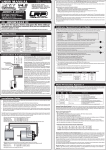
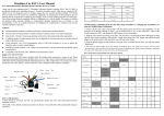
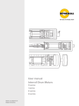
CUTTING EDGE WELDING USER’S MANUAL MIG 200 IGBT MIG 250 IGBT MIG 250 IGBT Single Phase MIG 315 IGBT EN MIG/MMA Dual Function IGBT Inverter Technology Compact Welding Power Source WARNING! Welding and cutting is dangerous to the operator, people in or near the working area, and the surrounding, if the equipment is not correctly operated. Therefore, the performance of welding/cutting must only be under the strict and comprehensive observance of all relevant safety regulations. Please read and understand this instruction manual carefully before the installation and operation. • The switching of function modes is possibly damaging to the equipment, while the welding operation is performed. • Do disconnect the electrode-holder cable with the equipment, after the performance of welding. • A safety switch is necessary to prevent the equipment from electric-leakage. • Welding tools should be of high quality. • Operators should be qualified. ELECTRIC SHOCK: It may be fatal • Connect the earth cable according to standard regulation. • Avoid all contact with live components of the welding circuit, electrodes and wires with bare hands. It is necessary for the operator to wear dry welding gloves while he performs the welding task. • The operator should keep the working piece insulating from himself/herself. Smoke and Gas generated while welding or cutting: harmful to people’s health. • Avoid of breathing the smoke and gas of welding or cutting. • Keep the working area in good ventilation Arc light-emission: harmful to people’s eyes and skin • Wear the welding helmet, anti-radiation glass and work clothes while the welding operation is performed. • Measures also should be taken to protect people in or near the working area. FIRE HAZARD • The welding splash may cause fire, thus remove flammable material away from the working place. • Have a fire extinguisher nearby, and have a ted fire person ready to use it. Noise: Possibly harmful to peoples’ hearing. • Surface noise is generated while welding/cutting, the hearing aids is necessary in some cases. Machine Fault: • Consult this instruction manual. • Contact your local dealer or supplier for further advice. 12 INDEX AN INTRODUCTION TO DC WELDERS 16. INSTALLATION 18. OPERATION 19. CAUTIONS 20. MAINTENANCE 21. BREAKDOWN-CHECKING 21. CIRCUIT DIAGRAM 24. 13 Introduction First of all, thank you for using our welders! Our welders are made with advanced inverter technology. The inverter power supply is to first rectifier the working frequency to 50/60HZ DC, and then inverter it to high frequency with high power factor IGBT (as high as 15KHZ), and rectifier again, and then use PWM to output DC power of high power factor, thus greatly reducing the weight and volume of the mains transformer and the efficiency is raised by 30%.The arc-leading system employs the principle of HF vibration. The main features are: stable, firm, portable, energy-saving and noiseless. The coming out of the inverter welders is considered as a revolution in the welding industry. The features of MMA serial is: perfect functions and satisfying all kinds of welding need, esp. places requiring welding of high quality, e.g. pipes, boiler, vacuum compressing Container, etc. Welcome friends of all works to use our products and give us your suggestion, we’ll contribute all to making our products and service better. 1. Maintenance for main engine is one year, excluding other spare parts. 2. During the maintenance period, all maintenance is fór free except intentional damage. 3. Customers are not allowed to unfold and refit or change the parts, or the consequent trouble is on you, and our company bears no duty over it. 14 The main parameter MIG 200 IGBT MIG 250 IGBTS MIG 250 IGBT MIG 315I GBT Input Power Voltage, Freq. 220±10%V, 50/60Hz 220±10%V, 50/60Hz 3x400±10%V 50/60Hz 3x400±10%V 50/60Hz (V, Hz) Rated Input Power Capacity (kVA) Rated Input Current (A) Output Current Range (A) MMA: 6,1 MIG: 6,6 MMA: 8,0, MIG: 9,2 MMA: 12, MIG: 14 MMA: 18, MIG: 22 MMA:10-180, MIG:50-200 MMA:10-220, MIG:50-250 MMA:8,0 MIG: 9,2 MMA:8,8 MIG: 9,9 MMA:12 MIG:14 MMA:18 MIG:22 MMA:10-220 MIG:50- MMA:10-270 MIG:50250 300 Rated Output Voltage (V) MMA:20-27, MIG:15- MMA:20-29, MIG:15- MMA:20-29 MIG:15- MMA:20-29 MIG:1526 28 29 30 Duty Cycle (%) Efficiency (%) Power Factor (Cosφ) Weight (kg) Size (mm) Insulation Class Protection Class Cooling Mains Fuse (A) Number of Wire Feeder rolls Diameter of Coil (mm) Welding Wire (mm) Order No. 60 60 60 60 85 85 85 85 0,93 0,93 0.93 0.93 48 49 50 51 1050x500x750 1050x500x750 1050X500X750 1050X500X750 F F F F IP21S IP21S IP21S IP21S AF AF AF AF 16 25 3x16 3x25 4 4 4 4 270 270 270 270 0.8-1.0 0.8-1.0 0.8-1.0 0.8-1.2 800MIG200IGBT 800MIG250IGBTS 800MIG250IGBT 800MIG315IGBT 15 2. Installation 2-1. Connection of the power wires 1. Each machine is equipped with primary powerwire, according tothe input voltage, please connect the primary wire to the suitable voltage class. 2. The primary wire should be connected to the corresponding socket to avoid oxidization. 3. Use multimeter to see whetherthe voltage value varies in the given range. Front panel Cylinder fixing Central connector Input cable 240V Electrode holder clamp (+) Gas input Earth clamp (-) Cooler 2-2. Connection of output wires 1. All machine has two air sockets, connect the plug to the socket on the panel board, and tighten it and make sure that it’s well-connected, or it may cause the damage of both the plug and socket. 2. The electrode holder wire is connected to the negative terminal, while the work piece is connected to the positive terminal; connect one terminal of the earth clamp to the red air plug, and tighten it with hexagon spanner to make the secondary wire well connected to the air plug, or the air plug may get burned. 3. Pay attention to the electrode of the wire. Generally, there are two ways of the DC welder connection: positive connection and negative connection. Positive: electrode holder to ,while work piece to “ + ” ; Negative: work piece to, while electrode holder to “+” ; Choose the way according to the practical requirements, and wrong choose may cause unstable arc and big splash, etc. Under this circumstance, renew the air plug rapidly in order to change the poles. 4. If the work piece is too far away from the machine (50-100m), and the secondary wire is too long, the section of the cable should be bigger to reduce the lower of the cable voltage. 5. You can find a MIG central connector to connect your MIG torch. Disconnect the electrode holder when weding in MIG mode. 16 2-3 Connect the wire feeder 1. The long axis of the wire feeder lock the wire roller that specific wire. Make sure that the wire roller is suitable for the wire used! 2. Wire should roll down clock wise, then cut the line, off-stage, it is only after pinning it on! 3. Tighten the hold-down screws on the wire, put the wire into the wire feed guide wheel and thread the wire to the welding torch. 4. Press the button on the wire feeder to the welding torch into the wire. 2-4. Checking 1. Whether the machine is connected to standard to earth. 2. Whether all the connections are well-connected. (esp. that between the earth clamp and the work piece) 3. Whether the output of the electrode holder and earth cable is short-circuited. 4. Whether the pole of the output is correct. 5. The welding splash may cause fire, so make sure there is no flammable materials nearby. Power indicator Protection indicator Power switch Current meter Voltage meter Wire feeder button Operation mode switch MIG/MMA function switch Welding current Welding voltage Wire speed Electronic Choke control 17 3. Operation Instructions 3-1. Operation Steps 1. Open the gas cylinder valve and adjust the flow meter to the desired position. 2. Welding Torch Nozzle sizes, choose the diameter of the wire under. 3. Set the current and voltage values of the workpiece thickness and material properly. 4. Induction controller button to adjust the desired position. 5. Press the torch button and start welding. 3-2. Welding current adjustment 1. Welding current and voltage directly affects the stability, quality and productivity of the welding process, pay attention to the choice of professional values. 2. Setting welding parameters based on other aspects of the wire diameter, penetration and production takes place. Following information should be subject to the selection of the welding current, depending on the type of work: Welding current and voltage band of continuous and batch operations Wire ø (mm) 18 Continuous Intermittent operation Current (A) Tunction (v) Current (A) Tunction (v) 0,6 40~70 17~19 160~400 25~38 0,8 60~100 18~19 200~500 26~40 1,0 80~120 18~21 200~600 27~40 1,2 1,6 100~150 140~200 19~23 20~24 300~700 500~800 28~42 32~44 HU 3-3. Choose a welding speed 1. Select welding speed affects the quality and productivity of welding. 2. When increasing welding speed, weakening the effectiveness of the shielding gas and the temperature falls, so the weld is not optimal training. If the speed is too low, the workpiece may be damaged suture training is not ideal. In practice, the welding speed should not exceed the 30m/ht. 3-4. Set the length of wire overhang 1. Long wire proper nozzle need to stretch out. If that is the length of a woman, increase productivity, but if it is too long, increases the spatter. 2. Usually this length is ten times the diameter of the welding wire must be. 3-5. Adjusting the flow rate of CO2 The primary efficacy criterion of protection. The small slope of welding protection, better performance than large slope. Primary parameters: Welding mode Thin wired CO2 welding Thick wired CO2 welding Thick wired power CO2 welding CO2 (l/min) 5~15 15~25 25~50 4. Precautions 4-1. Workspace 1. welding equipment free of dust, corrosive gas, non-flammable materials, up to 90% humidity for use! 2. Avoid welding outdoors unless protected from direct sunlight, rain, snow, work area temperature must be between -10 ° C and +40 °. 3. Wall to position the device at least 30 inches away. 4. well-ventilated area to perform welding. 19 4-2 . Safety requirements Welding provides protection against overvoltage / overcurrent / overheating. If any of the above events occurs, the machine stops automatically. However, overstress damage to the machine , keep the following guidelines : 1. Ventilation . When welding a strong current going through the machine , so the machine is not enough natural ventilation for cooling . The need to ensure adequate cooling, so the distance between the plane and any object around it at least 30 cm . Good ventilation is important to normal function and service life of the machine. 2. Continuously , the welding current does not exceed the maximum allowable value. Current overload may shorten its life or damage to the machine . 3. Surge banned ! Observance of feszültségsáv follow the main parameter table . Welding machine automatically compensates for voltage , allowing the voltage within permissible limits of law. If input voltages exceed the specified value , damaged parts of the machine . 4. The machine must be grounded! If you are operating in a standard, grounded AC pipeline in the event of grounding is provided automatically . If you have a generator or foreign , unfamiliar , non-grounded power supply using the machine , the machine is required for grounding connection point földelésvezetékhez to protect against electric shock . 5. Suddenly stopping may be during welding when an overload occurs or the machine overheats . In this case, do not restart the computer , do not try to work with it right away, but do not turn off the power switch , so you can leave in accordance with the built-in fan to cool the welding machines . 5. Maintenance 1. Remove power unit before maintenance or repair! 2. Ensure that proper grounding! 3. Make sure that the internal gas and electricity connections are perfect and tighten, adjust if necessary, if there is oxidation, remove it with sandpaper and then reconnect the cable. 4. Hands, hair, loose clothing should be kept away under electric parts, such as wires, fan. 5. Regularly dust from the machine clean, dry compressed air, a lot of smoke and polluted air to clean the machine every day! 6. The gas pressure is correct not to damage components of the machine. 7. If water would be, for example. rain, dry it in the machine and check the insulation properly! Only if everything is all right, go after the welding! 8 When not in use for a long time, in the original packaging in a dry place. 20