1
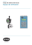
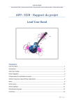
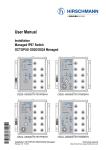
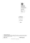
Operating Instructions DIGAP-3A-...
English
Valid for software version SW2.2
Digital Proportional Amplifier
For valves with DIN43650A-ISO4400 connection
DIGAP-3A-UKS, IKS
DIGAP-3A-US, IS
Cable connection with NPN switching output
Plug connection M12x1
BIBUS-Austria
Eduard-Klinger Strasse 12
A-3423 St.Andrä/Wördern
Tel: +43 2242 33388
Fax: +43 2242 3338810
Internet: www.bibus.at
Mail: [email protected]
Read these operating instructions carefully before installing and operating this product. Operation by technical staff only!
Pre – Conditions for the use of this product:
To ensure the safe and secure use of this product it should only be used according to specification and the general advice
must always be followed:
• Always follow the stated critical and limiting values according to specification, such as forces, temperatures and
voltage
• Consider ambient temperature and moisture
• Consider local laws and regulations
• Use this product only in the original and supplied shape, you must not carry out any modifications
• Remove all packaging and transit support
Stipulations of use:
Protection Category IP 65:
The Protection Category and the type test must not be applied to all applications.
The correct fitting of the socket, cables, wiring and other parts has to be approved and checked by user and operator.
Temperature:
Always bear in mind that the part could be heated by neighbouring appliances!
Also bear in mind that approved temperatures could burn and cause harm to human beings.
Technical data
Supply:
Residual ripple:
Output current:
Output power:
Chopper frequency:
Ramps up/down:
Temperature:
Power consumption:
Connector standard:
Protection class:
System supply:
Display:
Adjustment:
Weight:
Tariff:
11...30VDC
10%
up to 2,5A (2500mA)
60 W
100 ... 500 Hz
up to 10“, separately adjustable
from -25° to max. 70°C
15mA (24VDC)
DIN43650A-ISO4400 revolves + 90° ... max. 180°
IP65 (properly assembled)
4 /5) poll-socket M12x1, ISO/DIN or 2m PVC-cable / 5x0.5²
7-segment LED display, functions & values
programmable by keys inside housing
xKS = 280g including cable / xS = 72 g
90269090
EMV according to EN 61000-6-3:2001.10 EN 61000-6-2:2001.10
Accessories:
Angle plug:
Straight plug:
Sealing:
ELWIKA 5012 PG7 (required only for model US + IS)
ELKA 5012 PG7 (required only for model US + IS)
GDM3-7
Page 1 of 4
Operating Instructions DIGAP-3A-...
English
Valid for software version SW2.2
LED Symbols
Symbols – normal mode
Symbols – setting mode
Set point reached
Rise time (upward chute)
Downward regulating
Dropant time (downward chute)
Upwards regulating
Chopper frequency
Minimum reached (Offset)
Min. current (Offset)
Maximum reached (current limiting)
Max. current
Symbols
....
data
Graphic chart
0V- setting point
10V- setting point
Switching point OFF
Switching point ON
NOTE: The switching points are out of function at the design „DIGAP-3A-US“and „DIGAP-3A-IS“.
Manipulation
Set adjustments:
Push SET [s] to change into the setting mode.
Choose the setting mode with up [+] and down [-].
Push again SET [s], to see the data of the chosen function.
Change setting with up [+] and down [-].
Keep SET [s] pushed for 2 sec to save settings or push SET [s] shortly to get the
previous setting.
After 10 sec the amplifier is switching back to the normal mode.
Adjustment
Rise time: 0-10 sec, display: 0 – 9, disbanding 100 steps, factory setting: 1 sec
Drop out time: 0-10 sec, display: 0 – 9, disbanding 100 steps, factory setting: 1 sec
Setting point minimum: 0-100 %, display: 0 – 9, disbanding 1000 steps, factory setting: 0V=0 %
Setting: adjust the potentiometer to your chosen minimum point or put the chosen minimum setting onto the
port (0-10V). Now set the desired current at the DIGAP.
Notice: this setting can also be below the limit min. current.
Setting point maximum: 0-100 %, display: 0 – 9, disbanding 1000 steps, factory setting: 10V =70 %
Setting: adjust the potentiometer to your chosen maximum point or put the chosen maximal setting onto the
port (0-10V). Now set the desired current at the DIGAP.
Notice: this setting can also be over the limit max. current.
Limit min. current: 0-100 %, display: 0-9, disbanding 1000 steps, factory setting 0 %
(no voltage at the valve)
Warning! If you choose this setting mode the valve will be under the set current.
Be careful when changing this setting – an incorrect adjustment may result in an accident.
Limit max. current: 0-100 %, display: 0-9, disbanding 1000 steps, factory setting 75 %
Warning! If you choose this setting mode the valve will be under the set current.
Be careful when changing this of setting – an incorrect setting may result in an accident.
Chopper frequency: 100 – 500 Hz , display: 0 – 5, disbanding 500 steps, factory setting 150 Hz
Page 2 of 4
Operating Instructions DIGAP-3A-...
English
Valid for software version SW2.2
...-UKS / ...-IKS
Dimension and installation information
Installation PLC Control (no possibility of potentiometer installation):
wire colours:
brown:
white:
yellow:
green:
grey:
shield:
+VDC
-VDC (GND)
0-10V / 0-20mA input
10V output / auxiliary voltage
switching output, NPN, max. 200mA
PE / earth
RL:
Symbolic load, switching output
Page 3 of 4
Operating Instructions DIGAP-3A-...
English
Valid for software version SW2.2
...-IS / ...-US
Dimension and installation information
Installation PLC Control (no possibility of potentiometer installation):
plag configuration:
1 (brown):
+VDC
2 (white):
Analogue input
3 (blue):
-VDC (GND)
4 (black):
10 VDC OUT
5 (yellow/green): PE / earth
Please note that the wire colours in the bracket are not valid for
every supplier.
(Bitte beachten Sie dass die in Klammer angeführten
Aderfarben nicht für alle Hersteller gelten.)
Page 4 of 4