1
Instructions
Air Over Oil
Manifold Assembly
313848C
ENG
- Uses one-way air injectors to inject air into individual valve lube outlet ports -
Model No.: 24B237 (3 sections), 24B239 (4 sections), 24B240 (5 sections),
24B241 (6 sections)
Models without Air Sensor: 24J814 (3 sections), 24J815 (4 sections), 24J816
(5 sections), 24J817 (6 sections)
Can be mounted to standard, Graco MSP Divider Valve. See instruction manual 312497.
250 psi (1.7 MPa, 17 bar) Maximum Air and Fluid Working Pressure
Important Safety Instructions
Read all warnings and instructions in this manual.
Save these instructions.
US Patent Pending
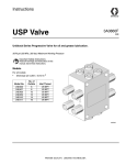
Model 24B237 shown attached to MSP Divider Valve
Warnings
Warnings
The following warnings are for the setup, use, grounding, maintenance, and repair of this equipment. The exclamation point symbol alerts you to a general warning and the hazard symbol refers to procedure-specific risk. Refer back
to these warnings. Additional, product-specific warnings may be found throughout the body of this manual where
applicable.
WARNING
PRESSURIZED EQUIPMENT HAZARD
Fluid from the gun/dispense valve, leaks, or ruptured components can splash in the eyes or on skin and
cause serious injury.
• Follow Pressure Relief Procedure in this manual, when you stop spraying and before cleaning,
checking, or servicing equipment.
• Tighten all fluid connections before operating the equipment.
• Check hoses, tubes, and couplings daily. Replace worn or damaged parts immediately.
EQUIPMENT MISUSE HAZARD
Misuse can cause death or serious injury.
• Do not operate the unit when fatigued or under the influence of drugs or alcohol.
• Do not exceed the maximum working pressure or temperature rating of the lowest rated system component. See Technical Data in all equipment manuals.
• Do not leave the work area while equipment is energized or under pressure. Turn off all equipment
and follow the Pressure Relief Procedure in this manual when equipment is not in use.
• Check equipment daily. Repair or replace worn or damaged parts immediately with genuine manufacturer’s replacement parts only.
• Do not alter or modify equipment.
• Use equipment only for its intended purpose. Call your distributor for information.
• Route hoses and cables away from traffic areas, sharp edges, moving parts, and hot surfaces.
• Do not kink or over bend hoses or use hoses to pull equipment.
• Keep children and animals away from work area.
• Comply with all applicable safety regulations.
2
313848C
Assembly Instructions
Assembly Instructions
Refer to FIG. 1 and FIG. 2.
B
A2
A3
C
A1
A4
1
2
3
4
5
6
A
G
Fig. 1
Key
A
B
C
D
E
F
G
D
F
PIN Configuration
PIN 1 - COM
PIN 2 - Not Used
PIN 3 - Normally Open
E
Valve mounting screw access port
Plug 1/8 NPSF (4 places) (Part No. 557776)
Injector kit (Part No. 24B246)
1/8 NPT
DIN 43650A Connector
Air Pressure Sensor (sold separately, Part No. 122375)
O-ring (Part No. 111710)
Torque Pattern - Torque to 8-9 ft. lbs (10.8-12.2 N.m)
1-6
2-5
3-4
Fig. 2
313848C
3
Installation Instructions
Installation Instructions
Pressure Relief Procedure
Follow this pressure relief procedure whenever you are
instructed to relieve pressure or need to check or service equipment.
1. Turn off power (air, electric, hydraulic) to lube supply
pump.
2. Turn off air supply to air manifold.
3. Place air over oil manifold over valves and hand
tighten all air injectors to seat manifold on the valve
stack. Then tighten air injectors with a wrench in a
star pattern until all o-rings are seated in o-ring
ports of valve and manifolds.
NOTE: The correct order is provided in chart on
page 3.
4. Using valve mounting screw access ports, torque all
valve mounting socket head cap screws to 8 - 9
foot/pounds (10.8 - 12.2 N•m).
5. The air supply may be induced into manifold using
available ports, A1, A2, A3, or A4.
4. Using a wrench, slowly loosen each outlet port fitting.
6. The air pressure sensor may be connected to any
available port not connected to the air supply. This
device warns of any blockage or breaks in the air
line.
5. Using a wrench, slowly loosen air inlet fitting.
NOTE:
3. Using a wrench, slowly loosen fluid inlet fitting.
•
Always use an air line filter of 40 micron or better to
remove dirt and moisture from the compressed air
supply.
•
Install an air regulator to allow pressure adjustment.
Assembly Instructions
NOTE: The Air Over Oil Manifold is designed to mount
to a standard Graco MSP divider valve. For instructions
on how to use an MSP divider valve, refer to instruction
manual 312497.
The Air Over Oil Manifold uses one-way air injectors to
inject air into each of the individual divider valve lube
outlet ports. Each air injector assembly is internally
checked to prevent oil from entering the air supply system.
The Air Oil Valve does not utilize common porting
between the lube outlets, therefore each outlet is both
pneumatically and hydraulically independent.
An air pressure sensor is provided to monitor for any
blockage or breaks in the air line.
Start Up Instructions
•
System must be pre-filled with 100 psi (0.69
MPa, 6.9 bar) of air pressure. Once system is
pre-filled and oil is being emitted from each distribution line, system air may be reduced to final
operating pressures.
•
Minimum operating air pressure is 45 psi (0.31
MPa, 3.1 bar).
•
Air pressure sensors are factory set to 35 psi
(0.24 MPa, 2.4 bar) (Models 24B237, 24B239,
24B240, 24B241 only).
The MSP divider valve can be used with a cycle indicator to monitor for proper oil lube cycles or blockage in
any of the lubrication lines.
1. Remove alternate outlet port plugs from divider
valves.
2. Loosen valve mounting socket head cap screws.
4
313848C
Technical Data
Technical Data
Maximum Air Working Pressure
Maximum Fluid Working Pressure
Lubricant
Air Inlet
Maximum Operating Temperature
Material
Air Sensor
Air Connection
Electrical Connection
Maximum Pressure
Fixed Setpoint
Setpoint Direction
Circuit Form
Current Rating
Diaphragm Material
313848C
250 psi (1.7 MPa, 17 bar)
250 psi (1.7 MPa, 17 bar)
Oils up to ISO 460 (2500 sus)
1/8 NPT female
200° F (93° C)
anodized aluminum, zinc plated steel, stainless steel,
chrome alloy steel, fluorocarbon
1/8 NPT male
DIN43650A, PIN 1 - COM, PIN 2 - Not used,
PIN3 - Normally Open
250 psi (1.7 MPa, 17 bar)
35 psi (.24 MPa, 2.4 bar)
Falling
SPST-NO (below 35 psi)
5A @ 250 VAC
5A @ 30 VDC (resistive)
Buna-N
5
Technical Data
Dimensions
B
A
D
C
6
Model
Dimension A
inch (mm)
Dimension B
inch (mm)
Dimension C
inch (mm)
Dimension D
inch (mm)
24B237
2.89 (73.4)
3.00 (76.2)
.718 (18.2)
3.75 (95.3)
24B239
3.815 (96.9)
3.00 (76.2)
.718 (18.2)
3.75 (95.3)
24B240
4.74 (120.39)
3.00 (76.2)
.718 (18.2)
3.75 (95.3)
24B241
5.665 (143.89)
3.00 (76.2)
.718 (18.2)
3.75 (95.3)
313848C
Notes
Notes
313848C
7
Graco Standard Warranty
Graco warrants all equipment referenced in this document which is manufactured by Graco and bearing its name to be free from defects in
material and workmanship on the date of sale to the original purchaser for use. With the exception of any special, extended, or limited warranty
published by Graco, Graco will, for a period of twelve months from the date of sale, repair or replace any part of the equipment determined by
Graco to be defective. This warranty applies only when the equipment is installed, operated and maintained in accordance with Graco’s written
recommendations.
This warranty does not cover, and Graco shall not be liable for general wear and tear, or any malfunction, damage or wear caused by faulty
installation, misapplication, abrasion, corrosion, inadequate or improper maintenance, negligence, accident, tampering, or substitution of
non-Graco component parts. Nor shall Graco be liable for malfunction, damage or wear caused by the incompatibility of Graco equipment with
structures, accessories, equipment or materials not supplied by Graco, or the improper design, manufacture, installation, operation or
maintenance of structures, accessories, equipment or materials not supplied by Graco.
This warranty is conditioned upon the prepaid return of the equipment claimed to be defective to an authorized Graco distributor for verification of
the claimed defect. If the claimed defect is verified, Graco will repair or replace free of charge any defective parts. The equipment will be returned
to the original purchaser transportation prepaid. If inspection of the equipment does not disclose any defect in material or workmanship, repairs will
be made at a reasonable charge, which charges may include the costs of parts, labor, and transportation.
THIS WARRANTY IS EXCLUSIVE, AND IS IN LIEU OF ANY OTHER WARRANTIES, EXPRESS OR IMPLIED, INCLUDING BUT NOT LIMITED
TO WARRANTY OF MERCHANTABILITY OR WARRANTY OF FITNESS FOR A PARTICULAR PURPOSE.
Graco’s sole obligation and buyer’s sole remedy for any breach of warranty shall be as set forth above. The buyer agrees that no other remedy
(including, but not limited to, incidental or consequential damages for lost profits, lost sales, injury to person or property, or any other incidental or
consequential loss) shall be available. Any action for breach of warranty must be brought within two (2) years of the date of sale.
GRACO MAKES NO WARRANTY, AND DISCLAIMS ALL IMPLIED WARRANTIES OF MERCHANTABILITY AND FITNESS FOR A
PARTICULAR PURPOSE, IN CONNECTION WITH ACCESSORIES, EQUIPMENT, MATERIALS OR COMPONENTS SOLD BUT NOT
MANUFACTURED BY GRACO. These items sold, but not manufactured by Graco (such as electric motors, switches, hose, etc.), are subject to
the warranty, if any, of their manufacturer. Graco will provide purchaser with reasonable assistance in making any claim for breach of these
warranties.
In no event will Graco be liable for indirect, incidental, special or consequential damages resulting from Graco supplying equipment hereunder, or
the furnishing, performance, or use of any products or other goods sold hereto, whether due to a breach of contract, breach of warranty, the
negligence of Graco, or otherwise.
FOR GRACO CANADA CUSTOMERS
The Parties acknowledge that they have required that the present document, as well as all documents, notices and legal proceedings entered into,
given or instituted pursuant hereto or relating directly or indirectly hereto, be drawn up in English. Les parties reconnaissent avoir convenu que la
rédaction du présente document sera en Anglais, ainsi que tous documents, avis et procédures judiciaires exécutés, donnés ou intentés, à la suite
de ou en rapport, directement ou indirectement, avec les procédures concernées.
Graco Information
TO PLACE AN ORDER, contact your Graco distributor or call to identify the nearest distributor.
Phone: 612-623-6928 or Toll Free: 1-800-533-9655, Fax: 612-378-3590
All written and visual data contained in this document reflects the latest product information available at the time of publication.
Graco reserves the right to make changes at any time without notice.
This manual contains English. MM 313848
Graco Headquarters: Minneapolis
International Offices: Belgium, China, Japan, Korea
GRACO INC. P.O. BOX 1441 MINNEAPOLIS, MN 55440-1441
Copyright 2009, Graco Inc. is registered to ISO 9001
www.graco.com
4/2009, revised 6/2011