1
Commercial Air Conditioning
SERVICE MANUAL
Models
AD182ALERA
AD362AHERA
Features
High energy efficiency
PAM control
Can be connected with the universal outdoor unit
Infrared control type or wired control type
Low ambient cooling kit (optional) and low ambient heating kit (optional)
New friendly refrigerant R410a, environment protection
Weekly timer (standard)
Group control function
Auto restart function
Manual code: SYJS-032-07REV.0
Edition: 2007-12-17
Commercial Air Conditioner
Model: AD182ALERA AD362AHERA
CONTENTS
Contents………………………………………………………..2
1. Description of products & features………………………..3
2. Specification…………………………………………………7
3. Safety precaution…………………………………………...9
4. Net dimension………………………………………………11
5. Parts and functions…………………………………………12
6. Installation instructions………..……………………………13
7. Controller functions…………………………………………25
8. Electrical control functions…………………………………26
9. Electrical data………………………………………………..34
10. Troubleshooting………………………………………........37
11. Noise level charts…………………………………….........47
2
Commercial Air Conditioner
Model: AD182ALERA AD362AHERA
1.DESCRIPTION OF PRODUCTS & FEATURES
1.1 Products code explanation
A
D 18
2
A L
E R A
Climate type: T1 (see table 1)
Design number (A-G stands for fixed frequency type, R-Z
stands for DC inverter frequency type)
Product type: A stands for heat pump type, refrigerant is R22
B stands for heat pump type, refrigerant is R407C
E stands for heat pump type, refrigerant is R410a
Q stands for cool only type, refrigerant is R410A
Outlook appearance
Product series: A stands for 1 to 1
Applicable voltage: 2 stands for 220~230V/50Hz,
4 stands for 220V/60Hz,N stand for 380~400VAC/50Hz
Cooling / Heating capacity,18=18000BTU/h
Product type : “B” stands for cassette type, “C” stands for
convertible type, ”D” stands for duct, “S” stands for wall
mounted type, ”Q” stands for chiller system, "E" stands for
ceiling concealed type, “U” stands for outdoor unit
Air Conditioner
1.2 Brief Introduction for T1、T2、T3 working condition
Climate type
Type
of
Conditioner
Air
T1
T2
T3
Cooling Only
18 ℃~43℃
10℃~35℃
21℃~52℃
Heat pump
-7℃~43℃
-7℃~35℃
-7℃~52℃
Electricity Heating
~43℃
~35℃
~52℃
1.3 Operating Range of Air Conditioners
Temp.
Mode
Indoor
Cooling
Outdoor
Indoor
Heating
Outdoor
Rated
Maximum
Minimum
DB
℃
27
32
15
WB
℃
19
23
14
DB
℃
35
43
10
WB
℃
24
26
6
DB
℃
20
27
10
WB
℃
14.5
---
--
DB
℃
7
23
-10
WB
℃
6
18
---
3
Commercial Air Conditioner
Model: AD182ALERA AD362AHERA
1.4 Product features
Adopt the much friendlier refrigerant R410a
The air conditioner system adopts the greatly friendly refrigerant R410a, which is protective for the
ozone layer and is good to avoid the earth getting warmer. Benefit for the environment.
Universal outdoor unit
The outdoor unit has been uniformed which can be connected with different type indoor units with
identical capacity such as cassette type, duct type, convertible type etc..
High efficiency filter
The unit adopts G3 grade filter, can efficiently filter the dirt etc, and improve the room air quality, at
the same time, the filter can pull out from downside, convenient for maintenance and cleaning.
Multi-mode for installation
The indoor unit can be installed with an air return duct or without an air return duct according to
the installation need.
PAM control
PAM adjusts the form of the current wave so that it becomes close to that of the supply voltage wave.
High harmonice are reduced and 99% of the electricity is utilized.
Auto–restart function (optional)
All indoor units have auto-restart function. When the power supply cut off suddenly, the unit will
automatically recover the previous running mode once the power supply is on.
Wider range operation of outside temperature
Group control function (with a group controller YR-E12)
Central control function, if connected with a central controller
YCZ-A001
Weekly timing function, if connected with a weekly timer YCS-A001
4
Commercial Air Conditioner
Model: AD182ALERA AD362AHERA
1.5 New friendly refrigerant R410A introduction:
■R410A
The working pressure of R410A is approximately 1.6 times higher than R22. Because the oil in the
refrigerant is different, please do not mix them.
Refrigerant
R22 (single)
R410A (mixed)
R407C (mixed)
Oil
Mineral oil (SONTEX 200LT)
Synthetic oil (POE oil)
Synthetic oil (POE oil)
Pressure ratio
1
Approx. 1.6
Approx. 1.1
■Operation flow
prepare work schedule
refrigerant inspection
1. Always inspect the used refrigerant
2. Always use the specified refrigerant
operation chart preparation
indoor unit installation
refrigerant piping work
1. Use piping material of the specified thickness
2. Do not use dirty pipe
3. Always flow nitrogen during welding work
drain piping work
duct work
insulation work
remote controller installation
electric wiring work
1. Do not connect the power supply
outdoor unit foundation work
outdoor unit installation
refrigerant piping connection
leakage test
evacuation and drying
additional refrigerant charging
1. Charge the nitrogen to the set pressure
2. 24 hours later,check if the pressure in the pipe
has reduced
1. Air purging by refrigerant is prohibited seriously
2. Use a special vacuum pump with reverse check
mechanism
1. Calculate the refrigerant additional charging
amount, and charge a suitable amount.
gas leakage check
maintenance panel installation
trial running and adjustment
hand over
5
Commercial Air Conditioner
Model: AD182ALERA AD362AHERA
■Piping material
1. Use the correct refrigerant piping and materials for R410A
2. For the pipe wall thickness, see the table below:
Pipe diameter
Φ6.35
Φ9.52
Φ12.7
Φ15.88
Φ19.1
Pipe wall thickness
0.8
0.8
0.8
1.0
1.2
Note: Always observe and comply with the local regulations when installing the refrigerant piping.
■Tools
R410A work requires a number of special tools (* symbol). Since the tools used in R22 work
cannot be used for R410A, provide the tools separately.
Tool name
Process and application
Pipe cutter
Piping cutting
*Flaring tool
Pipe flaring work
*Torque wrench
Flare nut connection
Expander
Expansion at pipe connection
Pipe bender
Pipe bending work
Nitrogen gas
Pipe oxidation prevention
Welder
Pipe brazing
*Gauge manifold
Vacuum
*Charging hose
charging operation check
Refrigerant piping work
evacuation
and
Air tightness test
refrigerant
Air tightness test
Refrigerant
additional
charging
*Vacuum
pump
(with
Vacuum drying
adapter)
Electronic scale
Gas leakage detector
Refrigerant
additional
charging
Gas leakage test
■Work precautions
Refrigerant check: Before work, check the used refrigerant and prepare materials matched to the
refrigerant.
Refrigerant piping: Observe the basics of refrigerant piping to avoid the unnecessary problems. In
addition, when performing the welding work, seal in the nitrogen gas to the pipes, and prevent it
from the oxidation.
Leak pressure detection: Perform seal detection and make sure there is no refrigerant leakage.
Vacuum drying: If the vacuum pump has not the reverse flow check mechanism, use the pump
together with a reverse flow check adapter.
Additional refrigerant: Charge a suitable amount of refrigerant with a special R410A gauge
manifold and charging hose.
6
Commercial Air Conditioner
Model: AD182ALERA AD362AHERA
2. SPECIFICATION
item
Function
Capacity
Total power input
Max. power input
EER or COP
Dehumidifying capacity
Running /Max.Running current
Start Current
Class of anti electric shock
Max. operating pressure of heat side
Max. operating pressure of cold side
Unit model (color)
Type × Number
Speed(H-M-L)
Fan
Fan motor output power
Air-flow(H-M-L)
Type / Diameter
Heat exchanger Total Area
Temp. scope
External
(L×W×H)
Dimension
Package
(L×W×H)
Drainage pipe (material , I.D./O.D.)
Control type (Remote /wired /model)
Noise level
(H-M-L)
Weight
(Net / Shipping)
Model
Indoor unit
AD182ALERA
cooling
heating
kW
4.8(1.8--5.8)
5.5(2.0---6.8)
1.65(0.55---2.65)
1.70(0.60---2.65)
KW
2650
2650
W
2.91(C)
3.24(C)
W/W
1.8
10‐³×m³/h
7.5(3.0---12.0)/12A
7.5(3.0---12.0)/12A
A/A
11
A
Class 1
4.15
Mpa
4.15
Mpa
AD182ALERA
Grey
centrifugal fan X 2
700±30 / 540±30 / 400±30
r/min
50
kW
780
m³/h
TP2M/7X0.5
mm
0.34
m²
2-7
℃
mm×mm×mm
1090×500×220
mm×mm×mm
1174×549×294
PVC 16/12
mm
wired control
45/41/37
dB(A)
23/26.5
kg / kg
Indoor unit
item
Model
Function
Capacity
BTU/h
Capacity
kW
Sensible heat ratio
Total power input
kW
Max. power input
W
W/W
EER or COP
Energy efficiency stage
Dehumidifying capacity
10‐³×m³/h
Running /Max.Running current
A/A
Unit model (color)
Type × Number
Speed(H-M-L)
r/min
Fan
Fan motor output power
kW
Air-flow(H-M-L)
m³/h
Type / Diameter
mm
Heat exchanger Total Area
m²
Temp. scope
℃
External
(L×W×H)mm×mm×mm
Dimension
Package
(L×W×H)mm×mm×mm
Drainage pipe (material , I.D./O.D.)
mm
Control type (Remote /wired)
Outlet distribution hole dimension
mm
Electricity Heater
kW
Noise level
(H-M-L)
dB(A)
Weight
(Net / Shipping)
kg / kg
7
AD362AHERA
heating
cooling
32400
38900
9.5(2.2~10.5)
11.4(2.5~12.0)
0.73
3.38(0.50---3.9)
3.15(0.50--3.9)
4300
4300
2.81
3.62
C
A
3.5
15.3(2.3-17.5)
15.0(2.3-17.5)
AD362AHERA(grey)
centrifugal X2
1090+30/-/930+50
0.4
2400/2070/1760
inner groove pipe /φ7
0.479
2-7
1197×830×350
1430×940×420
PVC 26/32
wired
853×254
0
50/46/42
62/70
Commercial Air Conditioner
Model: AD182ALERA AD362AHERA
Norminal condition: indoor temperature (cooling): 27℃DB/19℃WB, indoor temperature (heating): 20℃DB
Outdoor temperature(cooling): 35℃DB/24℃WB, outdoor temperature(heating): 7℃DB/6℃WB
The noise level will be measured in the third octave band limited values, using a Real Time Analyser calibrated sound intensity
meter. It is a sound pressure noise level.
Installation state: the unit should be placed on the flat floor or be mounted in horizontal direction.
Testing method:
duct unit with auxiliary duct:
2m
1m
auxiliary duct
auxiliary duct
1.4m
duct unit without auxiliary duct:
2m
duct
1.4m
Note: ⊙ is the real time
analyser position
8
Commercial Air Conditioner
Model: AD182ALERA AD362AHERA
3. Safety precaution
Carefully read the following information in order to operate the airconditioner correctly.
Below are listed three kinds of Safety Cautions and Suggestions.
WARNING! Incorrect operations may result in severe consequences of death or serious injuries.
CAUTION! Incorrect operations may result in injuries or machine damages; in some cases may
cause serious consequences.
INSTRUCTIONS: These information can ensure the correct operation of the machine.
Be sure to conform with the following important Safety Cautions.
The Safety Cautions should be at hand so that they can be checked at any time when needed.
If the conditioner is transferred to the new user, this manual should be as well transferred to the new user.
WARNING!
If any abnormal phenomena is found
(e. g.smell of firing), please cut off the
power supply immediately, and contact
the dealer to find out the handling
method.
Don't dismantle the outlet of the
outdoor unit.
The exposed fan is very dangerous
which may harm human beings.
In such case, to continue using the
conditioner will damage the conditioner,
and may cause electrical shock or fire
hazard.
switch
off
When the unit needs maintenance and
repairment, please call dealer to handle it.
After the unit being used for a long time,
the base should be checked for any
damages.
If the damaged base is not repaired, the
unit may fall down and cause accidents.
9
Incorrect maintenance and repairment
may cause water leak, electrical shock
and fire hazard.
Commercial Air Conditioner
Model: AD182ALERA AD362AHERA
WARNING!
Installed electrical-leaking circuit
breaker.
Nothing or nobody is permitted to
placed on or stand on outdoor unit.
It easily cause electrical shock without
circuit breaker.
The falling of goods and people may
cause accidents.
Air-conditioner can't be installed in
the environment with inflammable
gases because the inflammable gases
near to air-conditioner may cause fire
hazard.
Please let the dealer be responsible for
installing the conditioner.
Don't operate the air-conditioner with
damp hands.
Incorrect installation may cause water
leak, electrical shock and fire hazard.
Otherwise will be shocked.
Call the dealer to take measures to
prevent the refrigerant from leaking.
If conditioner is installed in a small
room be sure to take every measure in
order to prevent suffocation accident
Only use correctly-typed fuse.
even in case of refrigerant leakage.
May not use wire or any other materials
replacing fuse, other-wise may cause
faults or fire accidents.
When conditioner is removed or
reinstalled, dealer should be responsible
for them.
Incorrect installation may cause water
leaking, electrical shock and fire hazard.
Connect earthing wire.
Earthing wire should not be connected to the gas pipe, water pipe,
lightning rod or phone line, in-correct
earthing may cause shock.
Use discharge pipe correctly to ensure
efficient discharge.
Incorrect pipe use may cause water
leaking.
Earthing
10
Commercial Air Conditioner
Model: AD182ALERA AD362AHERA
4. Net dimension
AD182ALERA
_
[
^
Z
`
]
a
b
\
Z
[
\
]
^
_
`
a
b
5446
8<729
575
5549
699
549
<<4
=;4
664
AD362AHERA
1105
270
250
365
185
170
60
45
250
1200
800
830
1320
(mm)
11
Commercial Air Conditioner
5. Parts and Functions
AD182ALERA
Electrical components Case
Air outlet frame
Evaporator
Drain pan
AD362AHERA
XZXUJSINSL UTQJ
J[FUTWFYTWnNSXNIJo
LZFWINSL UQFYJ
XYTU [FQ[J
IZHY
JQJHYWNH GT]
XZXUJSINSL GTQY
IWFNS UNUJ
12
Model:
Commercial Air Conditioner
Model: AD182ALERA AD362AHERA
6. Installation Instructions
6.1 Installation for AD182ALERA
GbghU``Uh]cb gdUWY
Q\Y ]bXccf ib]h g\U`` VY ]bghU``YX Uh `cWUh]cbg k\YfY Wc`X UbX \ch U]f Wci`X YjYb`m W]fWi`UhYX2
Q\Y Zc``ck]b[ `cWUh]cbg g\ci`X VY Ujc]XYX>
M`UWYg k]h\ f]W\ gU`h -gYUg]XY UfYU.2
M`UWYg k]h\ d`Ybhm cZ [Ug gi`Z]XYg -aU]b`m ]b kUfa gdf]b[ UfYUg k\YfY h\Y WcddYf hiVY UbX VfUnY kY`X
]g YUgm hc Wcffcg]cb.2
IcWUh]cbg k]h\ aiW\ c]` -]bW`iX]b[ aYW\Ub]WU` c]`. UbX ghYUa2
IcWUh]cbg ig]b[ cf[Ub]W gc`jYbhg2
M`UWYg k\YfY h\YfY UfY aUW\]bYg [YbYfUh]b[ FD Y`YWhfcaU[bYh]W kUjYg2
Mcg]h]cbg UX^UWYbh hc Xccf cf k]bXck ]b WcbhUWh k]h\ \][\1\ia]X]hm YlhYfbU` U]f2 -CUgm hc [YbYfUhY XYk.2
IcWUh]cbg ZfYeiYbh`m ig]b[ gdYW]U` UYfcgc`g2
Q\Y Zc``ck]b[ dc]bhg g\ci`X VY hU_Yb WUfY cZ>
52 PY`YWh gi]hUV`Y d`UWYg h\Y cih`Yh U]f WUb VY gYbh hc h\Y
Ybh]fY fcca0 UbX WcbjYb]Ybh hc `Um cih h\Y WcbbYWh]cb
d]dY0 WcbbYWh]cb k]fY UbX h\Y XfU]bU[Y d]dY hc cihXccf2
62 Q\Y WY]`]b[ ghfiWhifY aigh VY ghfcb[ Ybci[\ hc giddcfh
h\Y ib]h kY][\h2
72 Q\Y WcbbYWh]b[ d]dY0 XfU]b d]dY UbX WcbbYWh]cb k]fY
w*~ t
g\U`` VY UV`Y hc [c h\ci[\ h\Y Vi]`X]b[ kU`` hc WcbbYWh
VYhkYYb h\Y ]bXccf UbX cihXccf ib]hg2
82 Q\Y WcbbYWh]b[ d]dY VYhkYYb h\Y ]bXccf UbX cihXccf ib]hg Ug kY`` Ug h\Y XfU]b d]dY g\U`` VY Ug g\cfh
Ug dcgg]V`Y2 -PYY D][ifY 5.
92 GZ ]hg bYWYggUfm hc UX^igh h\Y Z]``]b[ Uacibh cZ h\Y fYZf][YfUbh0 d`YUgY fYZYf hc h\Y ]bghU``Uh]cb aUbiU`
UhhUW\YX k]h\ h\Y cihXccf ib]h2
:2 Q\Y WcbbYWh]b[ Z`Ub[Y g\ci`X VY dfcj]XYX Vm h\Y igYf \]agY`Z2
;2 Q\Y ]bXccf ib]h \Ug hkc kUhYf cih`Yhg cbY cZ k\]W\ ]g cVghfiWhYX Uh h\Y ZUWhcfm -k]h\ U fiVVYf WUd.2 Lb`m
h\Y cih`Yh bch cVghfiWhYX -`]ei]X ]b`Yh UbX cih`Yh g]XY. k]`` VY [YbYfU``m igYX Xif]b[ ]bghU``Uh]cb2 GZ
Udd`]WUV`Y0 Vch\ h\Y cih`Yhg g\ci`X VY igYX hc[Yh\Yf2
KchY> Q\Y UWWYgg \c`Y aigh VY dfcj]XYX Xif]b[ ]bghU``Uh]cb cZ ]bXccf ib]h Zcf aU]bhYbUbWY2
8?K>I J>C><KBE@ KA> BEJK;CC;KBFE JG;<>6| GIF<>>= KA> ?FCCFMBE@ JK>GJ7
74 Djadd Y `gd] af l`] oYdd Yf\ afk]jl l`] [gff][laf_ hah] Yf\ oaj] l`jgm_` Y PVC oYdd3
l`jgm_` lmZ] hmj[`Yk]\ dg[Yddq4 T`] oYdd `gd] k`Ydd Z] oal` Y gmloYj\ \gof kdgh] g^ Yl
d]Ykl 757664 /S]] Fa_mj] 80
84 B]^gj] \jaddaf_ [`][c l`Yl l`]j] ak fg hah] gj j]af^gj[af_ ZYj bmkl Z]`af\ l`] \jaddaf_
hgkalagf4 Djaddaf_ k`Ydd Ynga\ Yl hgkalagfk oal` ]d][lja[ oaj] gj hah]4
94 Mgmfl l`] mfal gf Y kljgf_ Yf\ `gjargflYd Zmad\af_ jgg^4 I^ l`] ZYk] ak fgl ^aje2 al oadd
Fa_ 8
[Ymk] fgak]2 naZjYlagf gj d]YcY_]4
:4 Smhhgjl l`] mfal ^ajedq4
;4 C`Yf_] l`] ^gje g^ l`] [gff][lagf hah]2 [gff][lagf oaj] Yf\ \jYaf hah] kg l`Yl l`]q
[Yf _g l`jgm_` l`] oYdd `gd] ]Ykadq4
CUW\ cZ h\Y U]f gYbX]b[ XiWh UbX U]f fYhifb XiWh g\U`` VY Z]lYX cb h\Y dfYZUVf]WUhYX dUbY` cZ h\Y Z`ccf
Vm h\Y ]fcb VfUW_Yh2
Q\Y fYWcaaYbXYX X]ghUbWY VYhkYYb h\Y YX[Y cZ h\Y U]f fYhifb XiWh UbX h\Y kU`` ]g cjYf 594aa2
Q\Y [fUX]Ybh cZ h\Y WcbXYbgUhY kUhYf d]dY g\U`` _YYd cjYf 5,2
Q\Y WcbXYbgUhY kUhYf d]dY g\U`` VY h\YfaU` ]bgi`UhYX2
T\Yb ]bghU``]b[ h\Y WY]`]b[ AcbWYU`YX hmdY ]bXccf ib]h0 h\Y U]f fYhifb XiWh aigh VY XYg][bYX UbX
]bghU``YX -Ug Z][ifY g\ckb.2
13
Commercial Air Conditioner
Model: AD182ALERA AD362AHERA
Bmad\af_ jgg^ g^ afklYddYlagf
Yaj j]lmjf Zgp
Aaj gmld]l _jadd]
746e /mk] o`al] eglgj hdm_0
;46e/mk] j]\ eglgj hdm_0
Aaj kmhhdq
+
[]adaf_
mfal
Yaj j]lmjf Zgp
Yaj j]lmjf
Yaj kmhhdq
T`]j] k`gmd\ Z]
fg gZklY[d]k
oal`af 7e
mfal
Yaj j]lmjf
Ngl]@ W`]f [gff][laf_ l`] k`gjl \m[lk2 mk] l`] dgo klYla[ l]jeafYdk2 o`a[` [gdgj ak o`al]4
T`] \aklYf[] L ^jge l`] Yaj gmld]l g^ l`] \m[l lg l`] Yaj gmld]l g^ l`] kaj [gf\alagf]j k`Ydd Z] fg egj] l`Yf 7 e4
Smkh]f\af_ `ggc
DjYaf hah]
Aaj gml \m[l
Aaj j]lmjf \m[l
Aaj j]lmjf Zdaf\
TjYfkalagf \m[l
Aaj \akljaZmlYjq
Ta]3af g^ Yaj
\akljaZmlYjq
T`] kc]l[` eYh g^ dgf_ \m[l
Ngl]@ W`]f [gff][laf_ l`] dgf_ \m[lk2 mk] l`] ea\\d] klYla[ l]jeafYdk2 o`a[` [gdgj ak j]\4
T`] \aklYf[] L ^jge l`] Yaj gmld]l g^ l`] \m[l lg l`] Yaj gmld]l g^ l`] kaj [gf\alagf]j k`Yd Z] fg egj] l`Yf ; e4
M> oa\] ]phYfkagf Zgdl
M> kmkh]f\]j k[j]o
Aaj [gf\alagf]j
M> oa\] dg[c oYk`]j
M> k[j]o fml
IfklYddYlagf g^ af\ggj mfal \m[l
74 IfklYddYlagf g^ Yaj k]f\af_ \m[l
T`ak mfal mk]k jgmf\]\ \m[l2 l`] \aYe]l]j g^ l`] \m[l ak 7>6ee4
T`] jgmf\ \m[l f]]\k lg Y\\ Y ljYfkalagf \m[l lg [gff][l oal` l`] Yaj3k]f\af_ \m[l g^ af\ggj
mfal2l`]f [gff][l oal` j]kh][lan] k]hYjYlgj4 Ak Fa_4 7 k`gof2 Ydd l`] ^Yf kh]]\ g^ Yfq g^ l`] k]hYjYlgjvk
Yaj gmld]l k`Ydd Z] Y\bmkl]\ YhhjgpaeYl]dq l`] kYe] lg e]]l l`] j]imaj]e]fl ^gj l`] jgge Yaj [gf\alagf]j4
If\ggj mfal
^d]paZd] bgafl
TjYfkalagf \m[l
Rgmf\]\ \m[l
Ta]3af g^ Yaj
\akljaZmlYjq
Aaj \akljaZmlYjq
Fa_4 7
Ufal@ ee
84 IfklYddYlagf g^ Yaj j]lmjf \m[l
Uk] jan]l lg [gff][l l`] Yaj j]lmjf \m[l gf l`] Yaj j]lmjf afd]l g^ l`] af\ggj mfal2 l`]f [gff][l l`] gl`]j ]f\
oal` l`] Yaj j]lmjf Zdaf\4 Ak Fa_4 8 k`gof4
14
Commercial Air Conditioner
Aaj j]lmjf Zdaf\
Aaj j]lmjf \m[l
Model: AD182ALERA AD362AHERA
If\ggj mfal
jan]l
Fa_4 8
9 T`]jeYd afkmdYlagf g^ \m[l
Aaj3k]f\af_ \m[l Yf\ Yaj j]lmjf \m[l k`Ydd Z] l`]jeYddq afkmdYl]\4 Fajkl kla[c l`] _dm]q fYad gf l`] \m[l2 l`]f
YllY[` l`] `]Yl hj]k]jnYlagf [gllgf oal` Y dYq]j g^ laf^gad hYh]j Yf\ mk] l`] _dm]q fYad [Yh lg ^ap4 FafYddq mk]
l`] laf^gad Y\`]kan] lYh] lg k]Yd l`] [gff][l]\ hYjl4 Ak Fa_4 9 k`gof4
_dm]q
_dm]q `]Yl hj]k]jnYlagf
laf^gad fYad [Yh
[gllgf
fYad
Y\`]kan] lYh]
Fa_4 9
IfklYddaf_ l`] kmkh]fkagf k[j]o@
Uk] M> gj M76 kmkh]fkagf k[j]ok /:2hj]hYj]\ af l`] ^a]d\0/o`]f l`] kmkh]fkagf k[j]o`]a_`l ]p[]]\k 64?e2
M76 kar] ak l`] gfdq [`ga[]04T`]k] k[j]ok k`Ydd Z] afklYdd]\ Yk ^gddgok oal` khY[] Y\Yhlaf_ lg Yaj [gf\alagf]j
gn]jYdd \ae]fkagfk Y[[gj\af_ lg l`] gja_afYd Zmad\af_ kljm[lmj]k4
Wgg\]f kljm[lmj]
A kimYj] ogg\ k`Ydd Z] kmhhgjl]\ Zq l`] Z]Yek Yf\ l`]f k]l l`] kmkh]fkagf k[j]ok4
B]Ye
SimYj] ogg\
N]o [gf[j]l] kdYZ
Tg k]l oal` ]eZ]\\]\ hYjlk2^gmf\Ylagf Zgdlk ]l[4
Smkh]fkagf k[j]o
Ijgf j]af^gj[]e]fl
Fgmf\Ylagf Zgdl
Kfa^] ]eZ]\\]\ hYjl
Gma\] hdYl] ]eZ]\\]\ hYjl
Pah] kmkh]fkagf ^gmf\Ylagf Zgdl
Oja_afYd [gf[j]l] kdY\
HYf_af_ Zgdl
Uk] `gd] `af_]2`gd] hdmf_]j gj `gd] Zgdl4
Sl]]d j]af^gj[]e]fl kljm[lmj]
Uk] kl]]d Yf_d] gj f]o kmhhgjl kl]]d Yf_d] \aj][ldq4
Smkh]fkagf k[j]o
HYf_af_ g^ l`] af\ggj mfal
Smhhgjl kl]]d Yf_d]
FYkl]f l`] fml gf l`] kmkh]fkagf k[j]o Yf\ l`]f `Yf_ l`] kmkh]fkagf k[j]o af l`] T kdgl g^ l`] kmkh]fkagf
hYjl g^ l`] mfal4 Aa\]\ oal` Y d]n]d e]l]j2Y\bmkl d]n]d g^ l`] mfal oal`af ;ee4
x 4?QPGLK
If gj\]j lg \jYaf oYl]j fgjeYddq2 l`] \jYaf hah] k`Ydd Z] hjg[]kk]\ Yk kh][a^a]\ af l`]
afklYddYlagf eYfmYd Yf\ k`Ydd Z] `]Yl afkmdYl]\ lg Ynga\ \]o _]f]jYlagf4 Iehjgh]j `gk]
[gff][lagf eYq [Ymk] af\ggj oYl]j d]YcY_]4
15
Commercial Air Conditioner
Model: AD182ALERA AD362AHERA
NYei]fYaYbhg
P\Y ]bXccf XfU]b d]dY g\U`` VY h\YfaU` ]bgi`UhYX1
P\Y WcbbYWh]cb dUfh VYhkYYb h\Y XfU]b d]dY UbX h\Y ]bXccf ib]h g\U`` VY ]bgi`UhYX gc Ug hc dfYjYbh
XYk [YbYfUh]cb1
P\Y XfU]b d]dY g\U`` VY g`Ubh XckbkUfXg -[fYUhYf h\Ub 42433.1 P\Y a]XX`Y dUfh g\U`` bch VY cZ O hmdY
Y`Vck/ ch\Yfk]gY UVbcfaU` gcibX k]`` VY dfcXiWYX1
P\Y \cf]ncbhU` `Yb[h\ cZ h\Y XfU]b d]dY g\U`` VY `Ygg h\Ub 53 a1 Fb WUgY cZ `cb[ d]dY/ giddcfhg g\U``
VY dfcj]XYX YjYfm 418 q 5a hc dfYjYbh kUjm Zcfa1
@YbhfU` d]d]b[ g\U`` VY `U]X cih UWWcfX]b[ hc h\Y Zc``ck]b[ Z][ifY1
PU_Y WUfY bch hc Udd`m YlhYfbU` ZcfWY cbhc h\Y XfU]b d]dY WcbbYWh]cb dUfh1
418ao5a
Fbgi`Uh]cb-gidd`]YX
Vm h\Y igYf.
Oiddcfh
Ackb g`cdY
UVcjY 42433
O hmdY Y`Vck
SU``
Pc h\Y `Uf[Ygh -Udd1 43Wa.
Lihg]XY
RM63
O`Ubh
Ackb g`cdY UVcjY 42433
AfU]b d]dY -gidd`]YX
Vm h\Y igYf.
M]dY UbX ]bgi`Uh]cb aUhYf]U`
M]dY
N][]X MR@ d]dY RM53 aa -]bhYfbU` X]UaYhYf.
Fbgi`Uh]cb CcUaYX MB k]h\ h\]W_bYgg UVcjY : aa
EcgY
AfU]b d]dY g]nY= -627+. MR@ d]dY
P\Y \cgY ]g igYX Zcf UX^igh]b[ h\Y cZZ0WYbhYf UbX Ub[`Y cZ h\Y f][]X MR@ d]dY1
A]fYWh`m ghfYhW\ h\Y \cgY hc ]bghU`` k]h\cih aU_]b[ Ubm XYZcfaUh]cb1
P\Y gcZh YbX cZ h\Y \cgY aigh VY ZUghYbYX k]h\ U \cgY W`Uad1
EcgY
EcgY W`Uad
M`YUgY Udd`m h\Y \cgY cb \cf]ncbhU` dUfh
Fbgi`Uh]cb hfYUhaYbh=
SfUd h\Y \cgY UbX ]hg W`Uad ibh]` hc h\Y
]bXccf ib]h k]h\cih Ubm W`YUfUbWY k]h\
]bgi`Uh]b[ aUhYf]U`/ Ug g\ckb ]b h\Y Z][ifY1
OiVg]X]Ufm ]bgi`Uh]cb
AfU]b WcbZ]faUh]cb
Fbgi`Uh]cb
N][]X MR@ d]dY
Aif]b[ hf]U` fib/ W\YW_ h\Uh h\YfY ]g bc `YU_U[Y Uh h\Y d]dY WcbbYWh]cb dUfh Xif]b[ kUhYf XfU]b]b[ YjYb
]b k]bhYf1
u y{/.*,+
Fb ]bghU``Uh]cb/ ]Z h\YfY ]g fYZf][YfUbh [Ug `YU_U[Y/ d`YUgY hU_Y jYbh]`Uh]cb aYUgifYg ]aaYX]UhY`m1
P\Y fYZf][YfUbh [Ug k]`` [YbYfUhY dc]gcbcig [Ug idcb WcbhUWh]b[ Z]fY1
>ZhYf ]bghU``Uh]cb/ d`YUgY jYf]Zm h\Uh h\YfY ]g bc fYZf][YfUbh `YU_U[Y1 P\Y `YU_YX fYZf][YfUbh [Ug k]``
dfcXiWY dc]gcbcig [Ug k\Yb aYYh]b[ Z]fY gcifWY giW\ Ug \YUhYf UbX ZifbUWY YhW1
>``ckUV`Y d]dY `Yb[h\ UbX Xfcd
P\YgY dUfUaYhYfg X]ZZYf UWWcfX]b[ hc h\Y cihXccf ib]h1 OYY h\Y ]bghfiWh]cb aUbiU` UhhUW\YX k]h\ h\Y
cihXccf ib]h Zcf XYhU]`g1
M]dY aUhYf]U` UbX g]nY
16
Commercial Air Conditioner
PmdY
Model: AD182ALERA AD362AHERA
M\cgd\cfig XYcl]X]nYX WcddYf gYUa`Ygg
M]dY aUhYf]U` d]dY -PM5J. Zcf U]f WcbX]h]cbYf
Ccf gYf]Yg 4;5
M]dY g]nY
-aa.
p451:3
DUg g]XY
I]ei]X g]XY
p9168
Oidd`YaYbhUfm fYZf][YfUbh
P\Y fYZf][YfUbh gidd`YaYbhUh]cb g\U`` VY Ug gdYW]Z]YX ]b h\Y ]bghU``Uh]cb ]bghfiWh]cbg UhhUW\YX k]h\ h\Y
cihXccf ib]h1
P\Y UXX]b[ dfcWYXifY g\U`` VY U]XYX k]h\ U aYUgif]b[ aYhYf Zcf U gdYW]Z]YX Uacibh cZ gidd`YaYbhYX
fYZf][YfUbh1
NYei]fYaYbh
LjYfZ]``]b[ cf ibXYfZ]``]b[ cZ fYZf][YfUbh k]`` WUigY WcadfYggcf ZUi`h1 P\Y Uacibh cZ h\Y UXXYX fYZf][YfUbh
g\U`` VY Ug gdYW]Z]YX ]b h\Y ]bghfiWh]cbg1
@cbbYWh]cb cZ fYZf][YfUbh d]dY
@cbXiWh Z`UfYX WcbbYWh]cb kcf_ hc WcbbYWh U`` fYZf][YfUbh d]dYg1
P\Y WcbbYWh]cb cZ ]bXccf ib]h d]dYg aigh igY XciV`Y gdUbbYfg1
P\Y ]bghU``]b[ hcfeiY g\U`` VY Ug []jYb ]b h\Y Zc``ck]b[ hUV`Y1
SU`` h\]W_bYggcZ WcbbYWh]cb d]dY s 31;aa
@cbbYWh]b[ d]dY L1A1-aa.
FbghU``]b[ hcfeiY-K0a.
p9168
441; -415_[Z0a.
p<185
5718 -518 _[Z0a.
p451:3
7<13 -813 _[Z0a.
p481;;
:;17 -;13 _[Z0a.
AciV`Y0gdUbbYf cdYfUh]cb
RUWiia diad]b[
S]h\ U jUWiia diad/WfYUhY jUWiia Zfca h\Y ghcd jU`jY cZ h\Y cihXccf ib]h1
Badhm]b[ k]h\ fYZf][YfUbh gYU`YX ]b h\Y cihXccf ib]h ]g UVgc`ihY`m ZcfV]XXYb1
LdYb U`` jU`jYg
LdYb U`` h\Y jU`jYg cb h\Y cihXccf ib]h1
DUg `YU_U[Y XYhYWh]cb
@\YW_ k]h\ U `YU_U[Y XYhYWhcf cf gcUd kUhYf h\Uh ]Z h\YfY ]g [Ug `YU_U[Y Uh h\Y d]dY WcbbYWh]cbg
UbX VcbbYhg1
Fbgi`Uh]cb hfYUhaYbh
@cbXiWh ]bgi`Uh]cb hfYUhaYbh cb Vch\ h\Y [Ug g]XY UbX `]ei]X g]XY cZ d]dYg fYgdYWh]jY`m1
Aif]b[ Wcc`]b[ cdYfUh]cb/Vch\ h\Y `]ei]X UbX [Ug g]XYg UfY Wc`X UbX h\ig g\U`` VY ]bgi`UhYX gc Ug hc
Ujc]X XYk [YbYfUh]cb1
P\Y ]bgi`Uh]b[ aUhYf]U` Uh [Ug g]XY g\U`` VY fYg]ghUbh hc U hYadYfUhifY UVcjY 453 @
P\Y ]bXccf ib]h d]dY WcbbYWh]cb dUfh g\U`` VY ]bgi`UhYX1
P\Y bchW\ idkUfX->hhUW\YX XYhU]` j]Yk.
FbXccf ib]h
C]Y`X d]d]b[ g]XY
OiVg]X]Ufm ]bgi`Uh]cb hiVY
17
Commercial Air Conditioner
Model: AD182ALERA AD362AHERA
B`YWhf]W k]f]b[
S>NKFKD
A>KDBN LC ?LAFIT FKGQNT LN AB>PE
PQNK LCC BIB@PNF@ MLSBN >P @FN@QFP ?NB>HBN LN MLSBN OLQN@B ?BCLNB
J>HFKD >KT BIB@PNF@ @LKKB@PFLKO1 DNLQKA @LKKB@PFLKO JQOP ?B
@LJMIBPBA ?BCLNB J>HFKD IFKB RLIP>DB @LKKB@PFLKO1
-4. OY`YWh]cb cZ g]nY cZ dckYf gidd`m UbX ]bhYfWcbbYWh]b[ k]fYg1
MfYWUih]cbg Zcf B`YWhf]W k]f]b[
B`YWhf]W k]f]b[ kcf_ g\ci`X VY WcbXiWhYX cb`m Vm Uih\cf]nYX dYfgcbbY`1
Ac bch WcbbYWh acfY h\Ub h\fYY k]fYg hc h\Y hYfa]bU` V`cW_1 >`kUmg igY fcibX hmdY Wf]adYX hYfa]bU` `i[g k]h\
]bgi`UhYX [f]d cb h\Y YbXg cZ h\Y k]fYg1
QgY WcddYf WcbXiWhcf cb`m1
OY`YWh k]fY g]nYg UbX W]fWi]h dfchYWh]cb Zfca hUV`Y VY`ck1 -P\]g hUV`Y g\ckg 53 a `Yb[h\ k]fYg k]h\ `Ygg h\Ub 5, jc`hU[Y
@]fWi]h VfYU_Yf
M\UgY Ok]hW\ VfYU_Yf
->.
FhYa
Ccf gYf]Yg 4;5
4
BUfh\ `YU_U[Y VfYU_Yf
MckYf
gcifWY k]fY
IYU_
Ok]hW\
g]nY
WiffYb
VfYU_
LjYfWiffYbh
dfchYWhcf
73
59
518aa5
73>
63a>
vxw z*-*+~ |,++}|.*,+
JU_Y k]f]b[ hc gidd`m dckYf hc h\Y cihXccf ib]h/ gc h\Uh h\Y dckYf Zcf h\Y ]bXccf ib]h ]g gidd`]YX Vm hYfa]bU`g1
FKALLN QKFP
PBNJFK>I ?IL@H
LQPALLN QKFP
PBNJFK>I ?IL@H
I
K
MLSBN OQMMIT=
4ME/ 5530563Ro/ 83En
18
4
5
6
4
5
6
T2D
T2D
Commercial Air Conditioner
Model: AD182ALERA AD362AHERA
6.2 Installation for AD362AHERA
1. Before installation [Before finishing installation, do not throw the attached parts installation
needs]
Confirm the way to move the unit to the installation place.
Before moving the unit to the installation place, do not remove their packages.
When have to remove the package, use a soft material or protection board with rope to lift the unit assembly to
avoid unit damage or bumping a scrape.
2. Choose installation place
(1) The chosen installation place should meet the following requirements and get the users consent.
Place ensures ideal airflow distribution.
The passage of airflow has no obstacles.
When importing outside air, it should be imported directly from outdoors. (if the pipe can not be extended, it also can
not be imported from top)
Place ensures enough space for maintenance.
The pipe length between indoor and outdoor unit is in the permitted limit (referring to outdoor unit installation part).
The indoor unit, outdoor unit, electric wire and connection wire is at least 1m away from television and radio. This is
to avoid the image disturbance and noise caused by the above-mentioned home appliance. (Even if 1m away, if the
electromagnetic wave is too strong, it can also cause noise.)
(2) The height of ceiling
The indoor unit can install on the ceiling, which height is no more than 3m.
(3) Install and use the hoisting screw. Check if the installation place can bear the weight of unit assembly.
If not certain, strengthen it before install the unit.
(600x600)
Over 200
Air out
Over 900
Checking meatus
Over 300
Over 100
Air in
Ceiling
3. Preparation before installation
(1) The position relation among hoisting screw (unit: mm)
360
1270
853
794
250
Down side
Up side
1103
(2) If necessary, cut the opening installation and checking needed on the ceiling. (If has ceiling)
Before installation, finish the preparation work of all the pipes (refrigerant, drainage) and wire (wire controller
connection wire, indoor and outdoor unit connection wire) of indoor unit, so that after installation, they can be
immediately connected with outdoor unit.
Cut the opening on the ceiling. Maybe it needs to strengthen the ceiling to keep the ceiling even and flat and
prevent the ceiling from vibration. For details, please consult to the builder.
19
Commercial Air Conditioner
Model: AD182ALERA AD362AHERA
(3) Hanger bolts installation
Use care of the piping direction when the unit is installed.
(Use M10 screw bolt)
In order to bear the weight of the unit, for existed
ceiling, using foundation screw bolt, for new ceiling,
using burying embedded screw bolt, burying screw
bolt or spot supplied other parts.
Before going on installation, adjust the gaps with ceiling.
4. Installation of indoor unit
Fix the indoor unit to the hanger bolts.
If required, it is possible to suspend the unit to the beam, etc.
Directly by use of the bolts without using the hanger bolts.
Insert
Hole-in anchor
Hole-in plug
Concrete
Hanging bolt M10
Hanging bolt
M10 nut
M10 washer
M10 spring washer
Main unit
Note
When the dimensions of main unit and ceiling holes does not match, it can be adjusted with the slot holes of hanging
bracket.
Adjusting to the levelness
(a) Adjust the out-of levelness using a level or by the following method.
Make adjustment so that the relation between the lower surface
of the unit proper and water level in the hose becomes as given
below.
Piping side
Supply water
Water level
0~5 mm
(0~0.2")
PVC hose
Bring the piping side slightly lower.
(b) Unless the adjustment to the levelness is made properly, malfunctioning or failure of the float switch may occur.
5. Drain Piping
(a) Drain piping should always be in a downhill grade (1/50~1/100) and avoid riding across an elevation or making
traps.
Improper piping
Good piping
Suspension
1.5m ~ 2m
bolts
Avoid riding across an elevation
Keep free from traps
Air vent
Do not pipe under water
A downhill grade
Heat
insulation of 1/100 or more
(b) When connecting the drain pipe to unit, pay suffcient attention not to apply excess force to the piping on the unit
side. Also, fix the piping at a point as close as possible to the unit.
Stage
(c) For drain pipe, use hard PVC general purpose pipe VP-25(I.D.1")
which can be purchased locally. When connecting, insert a PVC
pipe end securely into the drain socket before tightening securely
using the attached drain hose and clamp. Adhesive must not be
used connection of the drain socket and drain hose (accessory).
difference Drain hose
Drain socket part
Drain socket
VP 25 joint
Pipe cover(large) (field purchased)
[for insulation]
(accessory)
Main unit
Drain hose
Clamp (accessory)
(accessory)
Adhesion
(d) When constructing drain piping for several units,
position the common pipe about 100 mm below
the drain outlet of each unit as shown in the sketch.
Use VP-30(11/4") or thicker pipe for this purpose.
Pipe cover(small)
[for insulation]
(accessory)
Pipe cover
[for insulation]
(field purchased)
Secure the elevation as high as possible
(approx. 100 mm)
(e) The stiff PVC pipe put indoor side should be heat insulated.
A downhill grade of
1/100 or more
20
VP 25
(field purchased)
VP 30
Commercial Air Conditioner
Model: AD182ALERA AD362AHERA
H2 H1
(f) Avoid putting the outlet of drain hose in the places with irritant gas generated. Do not insert the drain
hose directly into drainage, where the gas with sulfur may be generated.
(g) Backwater bend
Because the drain spout is at the position, which negative pressure may occur. So with the rise of
water level in the drain pan, water leakage may occur. In order to prevent water leakage, we designed a
backwater bend.
The structure of backwater bend should be able to be cleaned. As the below figure shown, use T
type joint. The backwater bend is set near the air conditioner.
As figure shown, set a backwater bend in the middle of drain hose.
H1=100mm or the static pressure of air sending motor
H2=1/2H1 (or between 50~100mm)
Drainage Test
1
2
3
4
Conduct a drainage test after completion of the electrical work.
During the trial, make sure that drain flows properly through the piping and that
no water leaks from connections.
In case of a new building, conduct the test before it is furnished with the ceiling.
Be sure to conduct this test even when the unit is installed in the heating season.
Procedures
1
2
Supply about 1000 cc of water to the unit through the air outlet using a feed water pump.
Check the drain while cooling operation.
6. Installation of air suction and discharging duct
muffler cavity (air sending)
Enlarging chart of
profile chart A
Vibration resistance hook
Sacking joint
Insulation
A
Air outlet
Air volume adjuster
Air conditioner
main unit
Ceiling
Air suction grille with air filter
Checking meatus
Please consult the after-sales service worker of Haier Air Conditioner for the choosing and installation
of suction inlet, suction duct, discharging outlet and discharging duct. Calculating the design drawing
and outer static pressure, and choose the discharging duct with proper length and shape.
The length difference among every duct is limited below 2:1.
Reduce the length of duct as possible as can.
Reduce the amount of bend as possible as can.
Use heat insulation material to bind and seal the part connecting main unit and the flare part of air
discharging duct. Perform duct installation work, before the ceiling fit.
Bad example
Bad example
Good example
21
Commercial Air Conditioner
Model: AD182ALERA AD362AHERA
7. Calculation method of the dimension of the simple quadrate air duct
Presuming the unit length friction impedance of the duct is 1Pa/m, when the dimension of one side of the air duct
is fixed as 250mm, as shown below:
A
>A695>EBN>
Air conditioner
AiWh -aalaa.
>]f jc`iaY
A
B
Static pressure box Equipped with
air filter (bought)
A
>
5733a62\
-73a62a]b.
583l643
?
933a62\
-43a62a]b.
583l453
The calculation of duct resistance (the simple calculation is as follow table)
Straight part
Calculate as per 1m length 1Pa, 1Pa/m
Bend part
Each bend takes as a3~4m long straight duct
Air out part
Calculate as 25Pa
Static pressure box
Calculate as 50Pa/each
Air inlet grille (with air filter)
Calculate as 40Pa/each
The chosen chart of simple duct
Note:1Pa/m=0.1mmAg/m
Shape
Item
Air volume
3
3
m /h(m /n)
100
200
300
400
500
600(10)
800
1,000
1,200(20)
1,400
1,600
Square duct
Shape
Dimension
Item
Air volume
(mmxmm)
m /h(m /n)
250
250
250
250
250
250
250
250
250
250
250
x
x
x
x
x
x
x
x
x
x
x
60
90
120
140
170
190
230
270
310
350
390
3
3
1,800(30)
2000
2400
3,000(50)
3,500
4,000
4,500
5,000
5,500
6,000(100)
Square duct
Dimension
(mmxmm)
250
250
250
250
250
250
250
250
250
250
x 430
x 470
x 560
x 650
x 740
x 830
x 920
x 1000
x 1090
x 1180
8. The attentive matters in installation of air suction and discharging duct
Recommend to use anti-frost and sound-absorbing
duct. (locally bought)
The duct installation work should be finished before the
fitment of ceiling.
The duct must be heat insulated.
The specific air-discharging outlet should be installed at
the place where the airflow can be reasonably distributed.
The surface should leave a checking meatus for checking
and maintenance.
Special air discharging outlet
Use screw bolt to fix
Duct
Air
Air
9. The examples of improper installation
Do not use air in duct and take the ceiling inner side instead. The result is because of the irregular
outer air mass, strong wind and sunshine, the humidity is increased.
There may be water drop on the outside of duct. For cement and other new constructions, even if not
taking ceiling inner side as duct, the humidity will also be so high. At this time, use glass fiber
to perform heat preservation to the whole. (use iron net to bind the glass fiber)
Maybe exceeding the unit operation limit (for example: when indoor dry bulb temperature is 35degree,
web bulb temperature is 24degree), it may lead to overload of compressor.
Affected by the capacity of air discharging fan, the strong wind in the outer duct and wind direction,
when unit air sending volume exceeds the limit, the discharged water of heat exchanger will overflow,
leading to water leakage.
22
Commercial Air Conditioner
Model: AD182ALERA AD362AHERA
Air discharging fan
Improper example
10. The operation method of fan controller
Through the fan controller switch in the electric box, the air volume of this unit can be continuously adjusted.
It is unnecessary to adjust air volume through the duct side wind level (unit outside static adjustment).
The air volume set should be in the operation air volume range.
Figure I shows the position of fan controller in the electric box and operation method.
After finishing the electric work, perform test run. According to the main points in Figure II making the chosen
switch No. accordant. And confirm if it reaches the needed air volume.
Note:
1) When operating the fan controller, it is possible to touch the electric charging part, so do cut off the
power supply.
2) Do not set the dial at the position less than 1.
3) The figure circled in Figure II indicate the capacity number of fan controller. The non-listed capacity
number may exceed the permitted operation capacity range, so it is impossible to operate.
4) When delivering from factory, the capacity number of fan controller is set at No.5.
Rotate this switch
200
*
Outer static pressure Pa
*
Once the fan controller
has trouble, this linker
can perform emergency
assistant control. When
this linker is connected
to the linker from the
PCB, it can operate with
total load.
When this linker is
connected to the linker
from the PCB, through
the fan speed adjustment
panel to adjust speed.
Condition of standard air volume
(air volume 100Pa)
High
Low
(capacity number
setting:
No. 1 ~ No. 8)
*
*
*
*
Example of
duct
* *
*
150
*
*
*
*
100
*
50
0
26
Lower limit
Figure 1
30
34 35
40
43
Upper limit
Standard air volume(m3/min)
Figure 2
The example of the method of choosing capacity number:
1) If the unit is in high-speed operation, needing take outer static pressure is 180Pa in capacity air volume
34m3/min as working condition point, according to Figure II The characteristic chart of air volume, the
capacity number of fan controller is No. 2.
2) If the unit is in low speed operation, needing take outer static pressure is 60Pa in capacity air volume
32m3/min as working condition point, according to Figure II The characteristic chart of air volume, the
capacity number of fan controller is No. 4.
11. Refrigerant pipe
[The air side pipe, liquid side pipe must be faithfully heat insulated, if no heat insulation, it may cause
water leakage.]
The outdoor unit has been charged with refrigerant.
23
Commercial Air Conditioner
Model: AD182ALERA AD362AHERA
When connect the pipe to the unit or dismantling the pipe from the unit, please follow the figure shown,
use spanner and torque spanner together.
When connect cone nut, the inner side and outside of cone nut should paste with refrigerant oil. Use
hand to twist 3-4 rings, then fasten with spanner.
Referring to Table I to confirm the fasten torque. (too tight may damage nut leading to leakage)
Check if the connection pipe leaks, then do heat insulation treatment, as below figure shown.
Only use seal cushion to bind the joint part of air pipe and heat insulation parts.
Middle size seal cushion (accessory)
(Use seal cushion to
bind the pipe joint)
Paste the refrigerant oil here
Torque spanner
Clamp
Heat insulation (accessory)
(for liquid pipe)
Heat insulation (accessory)
(for gas pipe)
Gas pipe
Liquid pipe
Spanner
Pipe joint
Cone nut
Liquid pipe
80
510
Gas pipe
Electric box
Upper
310
Air inlet
Specification of pipe Tighten torque
(mm)
9.52
3270~3990 N.cm
(333~407 kgf.cm)
Down side
30
530
Drain hose connection hole
VP25 PVC pipe
Cone dimension
A (mm)
12.0~12.4
Air outlet
Cone
45
90
2
R0.4~0.8
0.5
A
15.88
6180~7540 N.cm
(630~770 kgf.cm)
18.6~19.0
19.05
9720~11860 N.cm
(990~1210 kgf.cm)
22.9~23.3
5. Electric wiring
WARNING
DANGER OF BODILY INJURY OR DEATH
TURN OFF ELECTRIC POWER AT CIRCUIT BREAKER OR POWER SOURCE BEFORE
MAKING ANY ELECTRIC CONNECTIONS. GROUND CONNECTIONS MUST BE
COMPLETED BEFORE MAKING LINE VOLTAGE CONNECTIONS.
(1) Selection of size of power supply and interconnecting wires.
Precautions for Electric wiring
Electric wiring work should be conducted only by authorized personnel.
Do not connect more than three wires to the terminal block. Always use round type
crimped terminal lugs with insulated grip on the ends of the wires.
Use copper conductor only.
Select wire sizes and circuit protection from table below. (This table shows 20 m length wires with less
than 2% voltage drop.)
24
Commercial Air Conditioner
Item
Model
Model: AD182ALERA AD362AHERA
Power source Earth leakage breaker
wire size
Switch
Leak
Phase Switch breaker Overcurrent protector (minimum)
breaker(A)
current(mA)
(A)
rated capacity (A)
(mm2)
Circuit breaker
AD362AHERA
3
30
20
2.5
30
30
AD362AHERA
1
40
30
6.0
40
30
(2) Wiring connection
Make wiring to supply power to the outdoor unit, so that the power for the indoor unit is
supplied by terminals.
1 2 3
Y/G
1 2 3
Y/G
1 2 3
Y/G
R S TN 1 2 3
Y/G
INDOOR UNIT
TERMINAL BLOCK
OUTDOOR UNIT
TERMINAL BLOCK
LN
POWER SUPPLY:
1PH,220-230V~,50Hz
INDOOR UNIT
TERMINAL BLOCK
Y/G
OUTDOOR UNIT
TERMINAL BLOCK
POWER SUPPLY:
380-400V, 3N~,50Hz
25
Commercial Air Conditioner
Model: AD182ALERA AD362AHERA
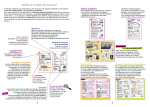
7. Controller functions
For duct type, the indoor unit can be controlled by wired controller YR-E12 as standard control
or by remote controller YR-H71 and remote receiver RE-01 as optional control.
;=34
50<
0BA=
0BA=
50< =<:F
7867
24<A?0:
=>4?0A8=<
2==:
;43
>?4-740A
3?F
740A
A4@
:=D
345?=@A
58:A4?
58E
740:A7
27429
@D8<6
B<8A <=.
34;0<3
;0<B0:
24<.033.
@[email protected].
A8;4?
2:=29 B>
@D8<6
50<
*
+
A4;>
740:A7
2:=29
?==; A4;>.
@4A A4;>.
A8;4?
@4A
?42=C4?F
27429
58:A4?
?4@4A
3=D< C4<A8:0A8=<
=<
0BA=
=55
?42=C4?F
308:F
;=34
@A0<31F
<=?;0:
=</=55
As for the connection method, please refer to below figures:
26
Commercial Air Conditioner
8. Electrical Control Functions
Model: AD182ALERA AD362AHERA
1.General features
1.1 Control mode: remotr or wired control + connecting port of long-distance control + passive
port control.
1.2 Temperature control: 16-30℃;
1.3 Precise of temperature control: ±1℃;
1.4 Indoor fan speed: AUTO, HIGH, MIDDLE, LOW (no AUTO when in FAN mode);
1.5 Swing control: the swing are controlled by the synchronous motor, main control board
receive usable signal and set in swing mode or remain in other mode;
1.6 running mode: AUTO , COOL, DRY, FAN and HEAT;
1.7 Healthy function: 5VDC UV generator, 12VDC negrative ion generator - high voltage
collecting-dirt, 220VAC negrative ion generator – oxygen pump;
1.8 Filter up-down control: adopt double-direction synchronous motor;
1.9 Auxiliary electric heating function: 12VDC control signal, 220VAC control signal or control
switch;
1.10 Fresh air control: 12VDC DC motor,220VAC AC control port output;
1.11 CLOCK setting, TIMER ON, OFF, ON/OFF and SLEEP fuction (only TIMER function is
viable and temperature variety is unviable when running the SLEEP function in FAN mode);
1.12 Drain system function: Water level inspection and water pump control
1.13 Compulsory cooling operation;
1.14 Safety and protection devices: 3-minute protection for compressor startup, freeze
protection device, overheat protection device, temperature cutoff protection, sensor failure,
drainage, pressure, communication etc. protection.
1.15 Indoor ambient temperature, indoor and outdoor coil temperature inspection.
1.16 start current control: the outdoor fan start after compressor running 2s in normal situation.
2. LED function:
The LED for remote control type includes POWER, TIMER, COMPRESSOR, WATER PUMP;
the POWER LED also indicate failure; when the unit is switched on by the controller, the POWER
LED will be ON, when being switched off, the POWER LED will be OFF.; If the controller is in TIMER
and SLEEP mode, the TIMER LED will be on; if it is not in TIMER and SLEEP mode, the TIMER LED
will be off. When the compressor is running, the compressor LED will be on; when it stops, this LED
will be off. POWER LED flashes when there are system failure, the flash times ti indicate the failure
code.
3. Indoor AUTO FAN control
a) If the unit enters AUTO FAN for the first time, when ΔT>2, select high speed; whenΔT≤
0, select low speed; or it will select
med speed; when thermostat is
High
OFF, fan will be low speed. (the
3
conversion temperature difference
High
is 1 degree).
ΔT
Mid
b)
If the present fan speed is AUTO
2
HIGH, whenΔT<2, fan speed will
1
change to AUTO MED.
Mid
Low
ΔT
c) If the present fan speed is AUTO
0
MED, whenΔT<0, fan speed will
change to AUTO LOW; whenΔT
Low
> 3, fan speed will change to
AUTO HIGH.
d) If the present fan speed is AUTO LOW, whenΔT>1, fan speed will chenge to AUTO MED.
e) Fan speed conversion in AUTO FAN mode: the conversion will delay for 3 minutes from HIGH to
LOW, and no delay from LOW to HIGH.
f) When the fan speed is HIGH/LOW/MED, on the condition that the protection does not act, the unit
will run at the set fan speed; when the protection acts, for the sake of the normal operation, the fan
speed will be forced to conversion; in Dry mode, fan motor will be changed as request.
4. AUTO mode control
4.1 When entering AUTO for the first time, the unit will select the running mode due to the below
27
Commercial Air Conditioner
Model: AD182ALERA AD362AHERA
Temp.
falling
conditions, then perform the selected mode.
Tr≥Ts-3℃ select COOL mode (includes FAN mode)
Tr<Ts-3℃
select HEAT or FAN mode
4.2 After entering the AUTO mode, the mode
can
change over among COOL, HEAT or FAN
cooling
modes according to the indoor ambient
temperature (conversion temperature difference
cooling
Ts+3℃
is ±3℃).
4.3 If the unit is in COOL mode, when it
arrives
compressor-stop
temperature,
the
compressor will stop; after compressor stops for
heating/blowing
Ts-3℃
15 minutes, the unit will check the room
temperature, if Tr < Ts-3 ℃ , the unit will enter
heating/blowing
HEAT or FAN mode, or the unit will still be in
COOL mode;
4.4 For the heat pump unit, if the unit is in HEAT mode at present, when it arrives
compressor-stop temperature, the compressor will stop; after the compressor stops for 15 minutes,
the unit will check the room temperature, if Tr>Ts+3℃, the unit will enter COOL mode, or it will still
be in HEAT mode.
4.5 For cooling only unit, if the unit is at FAN mode, if Tr>Ts+3℃, the unit will enter COOL mode.
4.6 When the unit is in HEAT mode, if indoor heat exchanger temperature rises up to over 63℃,
the unit will change into COOL mode. And within 1 hour, the heat exchanger temperature will not be
limited, the heating operation will stop temporarily. 1 hour later, the unit will select the proper mode
due to the above condition.
5. COOL mode control
5.1 4-way valve being powered off, compressor run/stop will depends on the temperature difference
between the room temperature and the set temperature.
5.2 In cooling mode, every time the compressor starts up, within 6 minutes, the compressor will not
be limited by the temperature sensor, but the set temperature change, shutoff signal and protection
action will not be limited by 6-minute protection, and the compressor can stop immediately.
5.3 ΔT≥1 compressor will run;
run
ΔT≤-1 compressor will stop;
run
-1<ΔT<1 compressor will stay in original state
1
ΔT
5.4 Anti-freezed protection (invalid in compulsory operation,
ΔT
trial running, heating mode)
-1
When the unit has run for over 6 minutes after compressor
stop
starts up, if indoor coil temperature Tg<1℃, the compressor
stop
and the outdoor motor will stop, and the unit will change to
FAN mode; 9 minutes later after compressor stops and when indoor coil temperature rises to 10℃,
the unit will resume to COOL mode, the compressor and the outdoor motor will run again.
5.5 Outdoor fan control: (realized by outdoor when with outdoor conmmunication function)
if the temp. of indoor coil sensor Tg<6℃, control the outdoor fan by the temp. of outdoor coil
sensor;
if the temp. of outdoor defrost sensor Tc<34℃, the outdoor fan will be OFF and lasted 45s at least;
if the temp. of outdoor defrost sensor Tc>44℃, the outdoor fan will be ON;
if the temp. of outdoor defrost sensor 34℃≤Tc≤44℃, the outdoor fan will remain in the original
state.
5.6 Temperature cutoff protection
In cooling mode, the unit will check indoor coil temperature every time the compressor has run for 1
minutes, when indoor coil temperature Tg>Tr+5, the unit will stop and 3 minutes later restart up; if
the temperature cutoff occurs for 3 times continuously, the unit will stop and alarm.
6. DRY mode control
6.1 When the uint enters DRY mode for the first time, the compressor, outdoor motor and indoor
motor will perform according to the below conditions:
ΔT>2, the compressor and the outdoor motor will run continuously, indoor motor will run at the set
Temp.
rising
28
Commercial Air Conditioner
Model: AD182ALERA AD362AHERA
speed, this area is defined as Area A;
0≤ΔT≤2, the compressor and the outdoor motor will always run for 10 minutes and then stop for 6
minutes, indoor motor will be LOW speed, this area is defined as Area B;
ΔT<0, the compressor and the outdoor motor will stop, indoor motor will run at Low speed, this area
is defined as Area C.
6.2 After the unit is running in DRY mode, the system will
A
change over among Area A, Area B, and Area C (the
3
A
conversion temperature difference ±1℃)
ΔT
B
If the system is in Area A, when ΔT<1, change to Area B;
1
If the system is in Area C, when ΔT>1, change to Area B;
1
B
If the system is in Area B, when ΔT>3, change to Area A;
C
ΔT
WhenΔT<-1, change to Area C.
-1
6.3 Anti-freezed protection (invalid in compulsory operation,
C
trial running, heating mode)
When the unit has run for over 6 minutes after compressor
starts up, if indoor coil temperature Tg<1℃, the compressor and the outdoor motor will stop, and the
unit will change to FAN mode; 9 minutes later after compressor stops and when indoor coil
temperature rises to 10℃, the unit will resume to COOL mode, the compressor and the outdoor
motor will run again.
6.4 Outdoor fan control: (realized by outdoor when with outdoor conmmunication function)
if the temp. of indoor coil sensor Tg<6℃, control the outdoor fan by the temp. of outdoor coil
sensor;
if the temp. of outdoor defrost sensor Tc<34℃, the outdoor fan will be OFF and lasted 45s at least;
if the temp. of outdoor defrost sensor Tc>44℃, the outdoor fan will be ON;
if the temp. of outdoor defrost sensor 34℃≤Tc≤44℃, the outdoor fan will remain in the original
state.
6.5 Temperature cutoff protection
In cooling mode, the unit will check indoor coil temperature every time the compressor has run for 1
minutes, when indoor coil temperature Tg>Tr+5, the unit will stop and 3 minutes later restart up; if
the temperature cutoff occurs for 3 times continuously, the unit will stop and alarm.
7. HEAT mode control
7.1 4-way valve control: in heating mode, compressor startup----4-way valve being electrified 10
seconds ahead; compressor running----4-way valve retains original state; compressor
shutoff----4-way valve being powered off 2 minutes and 50 seconds later (except for defrosting,
4-way valve being electrified 5 seconds ahead, and being powered off 55 seconds later).
7.2 In heating mode, for everytime the compressor startup (thermostat ON), within 6 minutes, the
4-way valve will not be limited by the temperature sensor, but for the set temperature change, shutoff
signal and the protection, the compressor can stop immediately without 6-minute limitation.
7.3 ΔT≥1 compressor running, indoor motor runs at anti-cold air mode;
ΔT≤-1 compressor stops, indoor motor runs at blowing remaining heat mode;
-1<ΔT<1 compressor retains original state
7.4 Overheat protection (for the unit with outdoor PCB, the outdoor motor is controlled by outdoor unit,
but the compressor is still controlled by indoor unit, and their temperature points will not be accordant
completely)
In heating mode, compressor has started up and indoor motor has run for over 30 seconds, if
indoor coil temperature Tg>60℃, outdoor motor will stop; if Tg<56℃, and outdoor motor has stop for
45s, outdoor motor will run again; if Tg>73℃, the compressor will stop and indoor motor will run
according to the thermostat state. After the compressor stops for 3 minutes and Tg reduces to 48℃,
the unit will resume to heating mode, and the compressor and the outdoor motor will run again.
7.5 Temperature cutoff protection
In heating mode (besides the defrosting), the unit will check indoor coil temperature every time the
compressor has run for 1 minutes, when indoor coil temperature Tg<Tr-5, the unit will stop and 3
minutes later restart up; if the temperature cutoff occurs for 3 times continuously, the unit will stop and
alarm.
29
Commercial Air Conditioner
Model: AD182ALERA AD362AHERA
7.6 Anti-cold air function in heating mode
After entering heating mode, or last defrosting is over, the compressor will start up, if Tg<28℃,
indoor motor will stop; if 38℃>Tg≥28℃, indoor motor will run at low speed; if Tg≥38℃ or the
compressor has run for over 4 minutes, indoor motor will run at the set speed; once the motor has
started up, it will not stop because of Tg reduction.
7.7 Blowing remaining heat function
In heating mode, the thermostat is OFF, the compressor stops, indoor motor will run at low speed
until Tg<28℃ and has run for 50 seconds at least.
Note: in heating mode, “the compressor stops----indoor motor delays to stop” adjust if the pipe
blows remaining heat; “the compressor startup----indoor motor delays to start up” adjust if the pipe is
anti-cold air; in other conditions, the compressor and the indoor motor are allowable not to be in
company. In cooling mode, the motor will run according to the control, not together with the
compressor.
7.8 Defrosting function in heating mode
In defrosting and when the compressor resumes to run for 3 minutes after defrosting is over, the unit
will not adjust the sensor failure.
7.8.1 Manual defrost: In heating mode, the set temperature 30℃ and in high speed, in 5 seconds,
press SLEEP button 6 times continuously, then the buzzer will sound 3 times, you can enter the
manual defrosting. At this moment, the unit will not adjust the enter condition of defrost and begin to
defrost function directly, whose procedure is as the same as the auto defrost; the quit condition is that
the defrosting time is up to 5 minutes.
7.8.2 Auto defrost enter condition: a) the compressor has run for 45 minutes continuously or for 75
minutes in all and has run for over 10 minutes continuously. b) the compressor and outdoor fan
running normally. c) the temp. of indoor coil sensor lower than 45℃, d) the defrosting temp. lower
than –8 ℃ (use the defrosting start signal from outdoor in the condition of with outdoor
communication ).
7.8.3 Auto defrost quit condition: The defrosting temp. over 14℃ or the defrosting time is over 12
minutes (use the defrosting end signal from outdoor in the condition of with outdoor communication )
7.8.4 Defrost process : a) enter defrosting mode, the compressor, outdoor and indoor fan motor stops;
b) 55 seconds later, 4-way valve will be reverse, after more 5 sensonds, compressor begins to run; c)
defrosting is over, compressor stops, outdoor fan running at high speed; d) 55 seconds later, 4-way
valve runs and compressor starts up. The indoor fan motor will run at anti-cold air condition.
7.8.5 For the unit with auxiliary electric heating function:
a. If the auxiliary electric heating function is working when the defrosting condition is met, please
stop electric heater firstly, 20 seconds later, defrosting can begin;
b. After defrosting, the unit will adjust the working state of electric heater according to the setting
before defrosting.
7.9 Auxiliary electric heating function (valid in heating mode or heating state in AUTO mode)
Enter condition: 1) ΔT>1; 2) Thermostat ON and running for 1 minute; 3) Tr<26℃; 4) Indoor motor
running; 5) Electric heating function start signal available (cancelled); 6) The system working in
heating mode or in heating state of AUTO mode; 7) Tg<48℃
If the above conditions can all be met, the electric heating function will work.
Quit condition: 1) ΔT≤1; 2) Thermostat OFF; 3) Tr>26℃; 4) Indoor motor stops; 5) Electric heating
function start signal not available (cancelled); 6) The system in non-heating operation; 7) Tg>52℃
If one of the above conditions can be met, the electric heater will stop.
8. FAN mode control
The compressor and the outdoor motor will stop running, indoor motor can be set at
high/med/low speed, the fan blade can swing or stay at one position. In this mode, you can set the
TIMER and SLEEP function.
9. CLOCK setting and TIMER function
The unit can set 24-hour TIMER ON/OFF, and the min. unit is 1 minute, after being set, the timer
lamp of indoor will be on, and after the timer is over, the timer lamp will be off.
TIMER ON: RUN LED is off, compressor LED is off, and TIMER LED is on, the unit is in stop state.
When timer is over, the unit begins to run, and the timer LED is off. The unit operation begins from
30
Commercial Air Conditioner
Model: AD182ALERA AD362AHERA
receiving the timer signal for the last time. The SLEEP function only can be set before the TIMER ON
begins.
TIMER OFF: the unit running, the timer LED on, while the timer is over, timer LED off, the unit will
stop, the sleep can be set, the sleep time will replace the original time of TIMER ON/OFF.
TIMER ON/OFF set at the same time: when the timer on/off is set, the timer LED will be off; the
SLEEP function can be set, the sleep time will replace the original time of TIMER ON/OFF.
10 SLEEP function (energy saving function at night)
101 Standard sleep function: in cooling or dry mode, after
Ts+2
running at SLEEP mode for 1 hour, the set temperature will
Ts+1
rise 1℃, another 1 hour later, the set temperature will rise
Ts
another 1℃; the unit continues running for 6 hours, then the
unit will stop.
10.2 Standard sleep function: in heating mode, after
running at SLEEP mode for 1 hour, the set temperature
Ts
reduces 2℃, another 1 hour later, the set temperature will
reduce 2 ℃ , and another 3 hours later, the set
Ts-2
temperature rises 1℃; the unit continues running for 3
Ts-3
Ts-4
hours, then the unit will stop.
10.3 Non-standard SLEEP function: the sleep function
can realize 1~8 hours sleep mode when being combined with the TIMER function.
1) When in Auto mode, the unit will make SLEEP operation due to the setting.
2) After setting SLEEP function, the clock can not be adjusted.
3) If sleep time is no more than 8 hours, when the time arrives, the unit wil shut off.
4) If sleep function is set after setting TIMER OFF function, the unit will execute as the SLEEP
function.
5) If SLEEP function is set, the TIMER function can not be set.
6) If sleep function is set after setting TIMER ON function, the sleep function only can be set
befroe the TIMER ON time arrives.
7) After setting sleep function, press CLOCK button to check the clock; press TEMP button to
display the set temperature, and press again to change the set temperature.
11 Water level inspection and water pump control
1) In COOL (including cooling state of AUTO mode and the compulsory cooling) and DRY mode, as
long as the compressor runs, water pump will work; and once the compressor stops, water pump will
stop 5 minutes later;
2) In standby state of cooling mode, heating mode and fan mode (including auto fan mode), after
water tank is full, the float switch will disconnect, if the controller detects this signal for 2 seconds,
the water pump will begin to work. After the float resets, water pump will continue working and
stops 5 minutes later;
3) If the water-full signal is detected for over 5 minutes, the compressor will stop; water pump will
work for 5 minutes and stop for 5 minutes, then repeat as a cycle, until the float resets, the water
pump will stop 5 minutes later; if water pump has repeated for 4 cycles, the float can not reset,
and the unit will alarm water drainage abnormal. And the water pump will continue the cycle.
12. System protection
12.1 3-minute protection for compressor startup
After the compressor stops, at least 3 minutes later, the compressor can restart up; the compressor
can restart up. Being electrifed for the first time, there is 3-minute delay protection.
12.2 Time shorting function
If the time shorting port is in short circuit, the unit will perform a 1/60 time shorting control.
12.3 High pressure protection
After compressor is running for 3 minutes, the unit will check the pipe pressure, when the pipe
pressure is too high, 30 seconds later, compressor and outdoor fan motor will stop, and then 3
minutes later, the unit will be normal. Within 30 minutes, if the compressor stops and will send
failure because of too high pressure for 3 times.
12.4 Low pressure protection
After compressor is running for 3 minutes, the unit will check the pipe pressure, when the pipe
31
Commercial Air Conditioner
Model: AD182ALERA AD362AHERA
pressure is too low and low pressure switch is running for 30 senconds, compressor and outdoor
fan motor will stop and will send failure
13. Trouble code
The remote receiver, wired controller and indoor PCB indicator all can indicate the failure code.
Remote
Wired
Central
control
controll
controll
indoor
Fault description
Possible cause
Remedy
er
er
PCB flash
display
display
times
Fault
in
drain Float switch is open 25m or due to the signal,
10
08(08H) 21D
system
Indoor
ambient
temp. sensor failure
1
01(01H)
01D
2
02(02H)
02D
Indoor pipe temp.
sensor failure
3
74(4AH)
11D
Outdoor
ambient
temp. sensor failure
4
73(49H)
12D
Outdoor pipe temp.
sensor failure
5
72(48H)
10D
Overcurrent
6
83(53H)
14D
7
71(47H)
22D
High
pressure
malfunction
Power failure
8
07(07H)
06D
9
06(06H)
05D
11
11(0BH)
30D
12
03(03H)
20D
13
13(0DH
)
76(4CH
)
31D
15
05(05H)
17D
16
84(54H)
26D
17
80(50H)
15D
18
12(0CH
)
23D
Fault in operation
mode
19
75(4BH)
18D
20
77(4DH
)
15D
Outdoor
coil
B(suction
sensor-multi)
Outdoor
discharge B (oil
temp
14
15D
longer
sensor broken down or short
circuit for more than 2m
continuously
sensor broken down or short
circuit for more than 2m
continuously
sensor broken down or short
circuit for more than 2m
continuously
sensor broken down or short
circuit for more than 2m
continuously
Detector CT current is above
the limit 3 times within 30m.
High pressure switch acts for
3 times in 30m
resumable
due to the signal,
resumable
due to the signal,
resumable
due to the signal,
resumable
due to the signal,
resumable
communication abnormal for
more than 4m continuously
Need
to
be
checked, reset
Need
to
be
checked, reset
Need
to
be
checked, reset
due to the signal,
resumable
communication abnormal for
more than 4m continuously
due to the signal,
resumable
External alarm is cut out for
10s or longer
sensor broken down or short
circuit for more than 2m
continuously
Directional valve malfunction
repeats 3 times
sensor broken down or short
circuit for more than 2m
continuously
due to the signal,
resumable
due to the signal,
resumable
EEPROM error
EEPROM data loss
Default
operation
Low
pressure
malfunction
Compressor
overheat
low pressure
activated
Communication
failure
between
wired controller and
indoor unit
Communication
failure
between
indoor and outdoor
units
External
alarm
signal input
Fault in coil/suction
line temp. sensor
Temperature
shut-off
Fault in discharging
temp. sensor
32
Wrong
phase,
failure or loss
phase
switch
Need
to
be
checked, reset
due to the signal,
resumable
is
Need
to
be
checked, reset
Detected temperature of
discharge line is higher
than 120℃
Indoor units operate in
different modes
Resrorable
when
lower
than 100℃
Resrorable in
same operation
sensor broken down or short
circuit for more than 2m
continuously
sensor broken down or short
circuit for more than 2m
continuously
mode
due to the signal,
resumable
due to the signal,
resumable
Commercial Air Conditioner
Model: AD182ALERA AD362AHERA
temp.
sensor-multi)
21
20(32D)
07D
Module failure
Module overheat, overcurrent,
short-circuit
22
36(54D)
08D
Fault in zero-load
Current sensor failure or
compressor is not started
due to the signal,
resumable
due to the signal,
resumable
14 Jumper selection (√shows jumper connected, ON; ×shows jumper disconnected, OFF; *
shows no limitation)
J1
J2
J3
J4
Wired control/ infrared √/×
*
*
*
control
Temp.
compensation *
*
*
√/×
available/not available
With/no outdoor PCB
*
*
*
√/×
Cooling only/heat pump
*
*
*
√/×
J5
J6
Time shorting switch
*
*
*
√/×
Forced or not
*
*
*
√/×
Ornarment or not
*
*
*
×/√
Oxygen or not
*
*
*
×/√
J7
J8
J9
J10
Other/2P convertible
*
*
*
√/×
single split/ multi split
*
*
*
√/×
Indoor unit address *
*
*
√/×
0/other
2P convertible /single *
*
*
√/×
blade
15. Network address selection (√shows jumper connected, ON; ×shows jumper disconnected,
OFF)
SW1
address
1
2
3
4
5
6
……
126
127
128
1
×
√
×
√
×
√
√
×
√
2
×
×
√
√
×
×
……
×
√
√
3
×
×
×
×
√
√
……
√
√
√
4
×
×
×
×
×
×
……
√
√
√
33
1
×
×
×
×
×
×
……
√
√
√
2
×
×
×
×
×
×
……
√
√
√
SW2
3
×
×
×
×
×
×
……
√
√
√
4
× shows
passive port
control AND
√ showes
passive port
control – the
later
entering in
priority
Commercial Air Conditioner
Model: AD182ALERA AD362AHERA
9. Electric data
9.1 Wiring diagram
AD182ALERA
0010576547
CIRCUIT DIAGRAM OF INDOOR UNIT
6
4
TRANS.
CN4
(12V/ALM)
5
CN5
R
Y/G
W B R Y/G
UP-DN
L-R
SWING
MOTOR
PUMP
MOTOR
9
(L)
Y
BL
M
Y/G
P15
P16 CN21
P17 SW3
1
(ROOM/PIPE) (FREEZE) SW2
CN8
CN6
SW1
(COMM)
P14
(H)
P13
(M)
P12
M
M
W
(L')
(N')
FLOAT
SWITCH
10
11
Y/G
M
P11
(PUMP)
(SWING)
(HUMI)
(OXYGEN)
P9 P10
W:WHITE B:BLACK
R:RED
Y:YELLOW
OR:ORANGE BL:BLUE
BR:BROWN
Y/G:YELLOW/GREEN
CAP.:FAN MOTOR CAPACITOR
TRANS.:TRANSFORMER
7
SW5
SW4
CN20
R
Y
M
B
1 2 3
P6(N4)
Y
OR
OR
P8
(HEAT)
P7
P5(N3)
8
13
CN19
2
CN7
P1(L)
W B
3
(FRESH)
P2(N)
(RECEIVE
BOARD)
(CONTROLLER)
FUSE
T3.15A/250VAC
P4(N2)
P3(N1)
CN12
(ALARM)
CN11
(DOOR)
14 CN15
(FLOAT)
B
A
CN16
(REMOTE)
CN13
CN14
(UP-DOWN)
ON ON
12 1234
CN17
ON ON ON
1234 1234 1234
CN1
WIRED
CONTROLLER
REMOTE
CONTROLLER
CENTRALIZED
REMOTE
RECEIVER
M
SWING
12 MOTOR ROOM
TEMP.
SENSOR
CAP.
CAP.
FAN MOTOR
W
PIPING TEMP.
SENSOR
NOTE: 1. PARTS 1
2 3 IN DASHED FRAME ARE NOT AVAILABLE
2. PARTS 4 5 6 ARE OPTIONAL, AND THE LINE MARKED 14 ONLY AVAILABLE IN CONVERTIBLE TYPE
3. PARTS AND CONNECTED WIRES IN DASHED FRAME 7 9 ARE NOT AVAILABLE IN CONVERTIBLE TYPE,
AND CORRESPONDINGLY THERE IS A CLIP ON PCB
4. PARTS AND CONNECTED WIRES IN DASHED FRAME 8 ARE NOT AVAILABLE IN DUCT TYPE
5. PARTS AND CONNCETED WIRES IN DASHED FRAME 10 11 DETERMINED BY PRODUCTS TYPE
6. PARTS AND CONNECTED WIRES IN DASHED FRAME 12 13 ONLY AVAILABLE IN AC***AFBEA TYPE
7. REFER TO OPERATION MANUAL TO SET SW1-SW5
TO OUTDOOR UNIT
AD362AHERA
0010576548
CIRCUIT DIAGRAM OF INDOOR UNIT
(RECEIVE BOARD)
P6(N4)
8
6
4
2
R
FC
9
B
1 2 3
W B R Y/G
TO OUTDOOR UNIT
Y/G
W
CN20
SW5
SW4
P14
BL
COM
NO
NC
8
6
4
2
7
5
3
1
CAP.
M
COM
NO
NC
Y/G
FAN MOTOR
7
5
3
1
8
6
4
2
COM
NO
NC
(H)
W
7
5
3
1
M
CAP.
P15
(COMM)
Y
P13
(M)
P12
(L)
(SWING)
P11
(PUMP)
P9 P10
P8
(HUMI)
P7
R
W B
CN19
2
3
P5(N3)
P1(L)
CN12
(ALARM)
CN11
(DOOR)
CN15
(FLOAT)
B
CN16
(REMOTE)
A
4
(OXYGEN)
CN7
(HEAT)
P2(N)
5
(CONTROLLER)
(FRESH)
CN5
P4(N2)
P3(N1)
FUSE
T3.15A/250VAC
WIRED
CONTROLLER
CN13
CN14
(UP-DOWN)
REMOTE
CENTRALIZED
CONTROLLER
(L')
(N')
P16
P17
W:WHITE B:BLACK
R:RED Y:YELLOW
OR:ORANGE BL:BLUE
BR:BROWN
Y/G:YELLOW/GREEN
CAP.:FAN MOTOR CAPACITOR
FC:FAN MOTOR SPEED
CONTROLLER
TRANS.:TRANSFORMER
FLOAT
SWITCH
CN21
SW3
(ROOM/PIPE) (FREEZE) 1 SW2
CN6
CN8
SW1
ROOM
TEMP.
SENSOR
ON ON
12 1234
CN17
CN4 (12V/ALM)
CN1
7
8
6
ON ON ON
1234 1234 1234
REMOTE RECEIVER
TRANS.
PIPING TEMP.
SENSOR
Y/G
FAN MOTOR
10
NOTE: 1. PARTS 1 2 3 4 5 IN DASHED FRAME ARE NOT AVAILABLE
2.PARTS 6 7 8 ARE OPTIONAL
3. PART 9 IS FAN MOTOR SPEED CONTROLLER KIT
4. PARTS 10 AND CONNECTED DASHED LINES ONLY AVAILABLE IN AD88NAHBEA
5. REFER TO OPERATION MANUAL TO SET SW1-SW5
34
Commercial Air Conditioner
Model: AD182ALERA AD362AHERA
0010451690E for AD182ALERA and AD362AHERA
CN11
SW5
CN15
CN21
SW3
SW4
SW2
CN12
SW1
CN16
CN8
CN6
CN13
LED1
CN14
P16
CN17
P17
CN20
P15
CN19
P14
P13
P12
LED5
P11
LED4
P10
CN7
P6
P9
CN5
P8
CN4
P5
P7
P1
CN1
P4
35
P3
P2
Commercial Air Conditioner
Model: AD182ALERA AD362AHERA
9.2 Sensor characteristic
name
model
sub-part code
code
characteristic
ambient temperature sensor
0010451323
001A3900003
coil temperature sensor
001A3900006
001A3900004
ambient temperature sensor
001A3900005
001A3900003
coil temperature sensor
0010401922
001A3900004
AD182ALL ERA
AD362AHERA
R25=23KΩ±2.5%
B25/50=4200K±3%
R25=23KΩ±2.5%
B25/50=4200K±3%
R25=10KΩ±3%
B25/50=3700K±3%
R25=23KΩ±2.5%
B25/50=4200K±3%
R25=10KΩ±3%
B25/50=3700K±3%
R25=10KΩ±3%
B25/50=3700K±3%
T(℃)
Rnom(KΩ)
T(℃)
Rnom(KΩ)
T(℃)
Rnom(KΩ)
T(℃)
Rnom(KΩ)
T(℃)
Rnom(KΩ)
-20℃
281.34
24℃
24.12
-20℃
90.79
24
10.43
68
2.09
-19℃
263.56
25℃
23
-19
85.72
25
10
69
2.03
-18℃
247.04
26℃
21.94
-18
80.96
26
9.59
70
1.96
-17℃
231.66
27℃
20.94
-17
76.51
27
9.21
71
1.9
-16℃
217.35
28℃
19.99
-16
72.33
28
8.84
72
1.85
-15℃
204.02
29℃
19.09
-15
68.41
29
8.48
73
1.79
-14℃
191.61
30℃
18.23
-14
64.73
30
8.15
74
1.73
-13℃
180.04
31℃
17.42
-13
61.27
31
7.83
75
1.68
-12℃
169.24
32℃
16.65
-12
58.02
32
7.52
76
1.63
-11℃
159.17
33℃
15.92
-11
54.97
33
7.23
77
1.58
-10℃
149.77
34℃
15.22
-10
52.1
34
6.95
78
1.54
-9℃
140.99
35℃
14.56
-9
49.4
35
6.68
79
1.49
-8℃
132.78
36℃
13.93
-8
46.86
36
5.43
80
1.45
-7℃
125.11
37℃
13.34
-7
44.46
37
5.6
-6℃
117.93
38℃
12.77
-6
42.21
38
5.59
-5℃
111.22
39℃
12.23
-5
40.08
39
5.73
-4℃
104.93
40℃
11.71
-4
38.08
40
5.52
-3℃
99.04
41℃
11.22
-3
36.19
41
5.32
-2℃
93.52
42℃
10.76
-2
34.41
42
5.12
-1℃
88.35
43℃
10.31
-1
32.73
43
4.93
0℃
83.5
44℃
9.89
0
31.14
44
4.9
1℃
78.94
45℃
9.49
1
29.64
45
4.58
2℃
74.67
46℃
9.1
2
28.22
46
4.42
3℃
70.65
47℃
8.74
3
26.4
47
4.26
4℃
66.88
48℃
8.39
4
25.61
48
4.11
5℃
63.33
49℃
8.05
5
24.41
49
3.97
6℃
60
50℃
7.73
6
23.27
50
3.83
7℃
56.86
51℃
7.43
7
22.2
51
3.7
8℃
53.91
52℃
7.14
8
21.18
52
3.57
9℃
51.13
53℃
6.86
9
20.21
53
3.45
10℃
48.51
54℃
6.6
10
19.3
54
3.33
11℃
46.04
55℃
6.34
11
18.43
55
3.22
12℃
43.72
56℃
6.1
12
17.61
56
3.11
13℃
41.52
57℃
5.87
13
16.83
57
3.11
14℃
39.45
58℃
5.65
14
16.09
58
2.9
15℃
37.5
59℃
5.44
15
15.38
59
2.81
16℃
35.66
60℃
5.24
16
14.71
60
2.72
17℃
33.92
17
14.08
61
2.63
18℃
32.27
18
13.48
62
2.54
19℃
30.72
19
12.9
63
2.49
20℃
29.25
20
12.36
64
2.38
21℃
27.86
21
11.84
65
2.3
22℃
26.54
22
11.34
66
2.23
23℃
25.3
23
10.87
67
2.16
36
Commercial Air Conditioner
Model: AD182ALERA AD362AHERA
10. Troubleshooting
1) Pressure protection
Confirm the fault according
to the fault code list
no
Does system have
pressure switch?
Are CN17 and CN18
in PCB cut off?
no
Replace PCB
yes
yes
Make them in
short circuit
Is actual pressure detected by
pressure gage acceptable?
no
no
low pressure failure
yes
Change pressure
switch
high pressure failure
yes
yes
Is high pressure too low?
no
is pipe blocked?
yes
yes
Refrigerant charge is
needed. Check if there is
refrigerant leak. If yes,
replace pipe.
dredge piping
Note: The confirmation time of low pressure failure may be shorter, but high pressure failure confirmation
time is at least 1 hour. Besides, take the ambient temperature into consideration.
2) Sensor failure
check if the wiring is
correct according to
wiring diagram
if sensor is fixed
well
no
reconnect
no
Relocate
yes
Is sensor short-circuit
or open-circuit?
yes
Replace sensor
yes
Is sensor resistance
acceptable?
no
Replace sensor
yes
Is DC voltage between
both ends of sensor
near 5V or 0V?
no
Replace PCB
37
Commercial Air Conditioner
3) Low pressure protection
Confirm the fault according
to the fault code list
yes
no
Are connectors of pressure switch in good
condition?
Check and reconnect
yes
Is low side pressure switch
activated? (If not, DC voltage is 0V.)
no
Replace PCB
yes
Is the low side pressure detected by
the gage lower than threshold value?
The threshold value is indicated on
the switch
no
Replace low pressure
switch
yes
no
if outdoor stop valves of gas pipe
and liquid pipe are open totally
Open the valves
yes
yes
Is piping twisted or deformed?
Repair pipe
no
Does indoor fan work properly during
cooling cycle? Does outdoor fan work
properly during heating cycle?
no
Repair fan motor or fan
capacitor
yes
Is indoor filter or heat
exchanger dirty?
yes
Cleaning
no
Measure equalized pressure and time to
reach equalization to see if the system has
leakage. Lack of refrigerant? Is capillary
blocked?
yes Conduct leak test.
Evacuate and recharge
no
Bad operation codition, such as ultra low
outdoor temperature
38
Model: AD182ALERA AD362AHERA
Commercial Air Conditioner
Model: AD182ALERA AD362AHERA
4) High pressure protection
Confirm the fault according
to the fault code list
yes
Are connectors of pressure switch in good
condition?
no
Check and reconnect
yes
Is high side pressure switch
activated? (If not, DC voltage is 0V.)
no
Replace PCB
yes
Is the high side pressure detected by
the gage higher than threshold
value? The threshold value is
indicated on the switch
no Replace high pressure
switch
yes
if outdoor stop valves of gas pipe
and liquid pipe are open totally
no
Open the valves
yes
yes
Is piping twisted or deformed?
Repair pipe
no
Does indoor fan work properly during
cooling cycle? Does outdoor fan work
properly during heating cycle?
no
Repair fan motor or fan
capacitor
yes
Is indoor filter or heat
exchanger dirty?
yes
Cleaning
no
Check if system is overfed according
to equalized pressure in halt.
yes
Evacuate and recharge
no
Is reading of discharging pressure
gage oscillatory?
no
Bad operation codition, such as ultra low
outdoor temperature
yes
There is air in system.
Evacuate and recharge
39
Commercial Air Conditioner
Model: AD182ALERA AD362AHERA
5) Communication error between indoor and outdoor units
Confirm commumication failure
according to the fault code list
Confirm the fault indicator is
communication failure
yes
Does indoor communication
indicator flash?
Are communication wire
S and supply wires L and
N properly connected?
Grounded well?
no
no
re-wiring
yes
check the other
reasons
yes
Is communication wire too
no close to power cable, which
causes interference?
yes
if communication wire
is broken
yes
re-wiring
no
S should not share
a multicore cable
with L and N
check if indoor/outdoor PCB fuse
and transformer are normal
no
change
defective parts
yes
replace indoor PCB
if failure is eliminated
no
replace outdoor PCB
6) Communication failure between wired controller and indoor PCB
or no display on wired controller
Confirm commumication failure
according to the fault code list
or no display
no
check if the wired controller
can match with indoor PCB
replace wired controller
yes
Is power just turned on?
yes
no
for some models, when powered on,
initialization will display 88, if initrialization
cannot finish, check indoor dip switch position
Is voltage between A and yes Is voltage between B yes
B of wired controller 12V?
and C fluctuating?
no
no
yes
Is supply transformer or 7812
check if wiring
component in good condition?
is correct
no
check if failure disappears after
changing transformer or PCB
no
check if failure disappears after yes wired controller is
changing wired controller
broken
40
check if the dip
yes
switch position on
replace PCB
PCB is right
no
correct the position
Commercial Air Conditioner
Model: AD182ALERA AD362AHERA
7) High current protection in 3-phase fixed frequency models
Is three-phase circuit not
balanced? Is supply voltage too
low? Is supply voltage too low at
compressor start-up?
yes
Modify power supply circuit
yes
Is power cable or compressor wire
securely connected? Properly?
no
re-wiring
yes
Is compressor current more than overcurrent
protection limit? Is current detecting circuit in
good condition?
no
Confirm detecting circuit
is abnormal,replace
outdoor PCB
yes
Is AC contactor in
poor contact?
yes
replace AC contactor
yes
if compressor is normal
no
Is resistance of compressor
winding incorrect? Is it stuck?
yes
replace compressor
yes
if pressure is normal
no
Check: 1. Is a valve in system shut off;
2. Is piping clogged;
3. Is system overfed; is there air in system;
4. (Cooling cycle) Is condenser dirty? Does outdoor fan motor run at low speed or stop?
5. (Heating cycle) Is evaporator or filter dirty? Does indoor fan motor run at low speed or stop?
6. Is ambient temperature too high? Is system overloaded?
8) External alarm
An external alarm is
identified according to the
list of fault codes
Is an external alarm
connected to the system?
no
yes
Solve problem
accordingly
Is ALARM terminal in
mainboard disconnected?
yes
Short connect that
terminal
yes
if failure disappear after
PCB is changed
no
replace PCB
41
Commercial Air Conditioner
Model: AD182ALERA AD362AHERA
9) Overcurrent protection for single-phase fixed frequency models
Is supply voltage too low? Especially
when compressor starts up?
yes
modify power supply circuit
no
Is supply wire securely
connected?
no
re-wiring
yes
Is compressor current more than overcurrent
protection limit? Is current detecting circuit in
good condition?
no
Confirm detecting circuit
is abnormal,replace
outdoor PCB
yes
Is compressor in
good condition?
no
Is resistance of compressor
winding incorrect? Is it stuck?
no
replace running capacitor
yes
replace compressor
yes
Is running capacitor in
good condition?
yes
Is pressure normal?
no
Check: 1. Is a valve in system shut off;
2. Is piping clogged;
3. Is system overfed; is there air in system;
4. (Cooling cycle) Is condenser dirty? Does outdoor fan motor run at low speed or stop?
5. (Heating cycle) Is evaporator or filter dirty? Does indoor fan motor run at low speed or stop?
6. Is ambient temperature too high? Is system overloaded?
42
Commercial Air Conditioner
Model: AD182ALERA AD362AHERA
10) Temperature cutoff protection
confirm the malfunction
according to the fault code list
Is outdoor four-way valve
in good condition during
heating cycle?
Does small relay coil
of four-way valve have
a voltage of 12V DC?
no
yes
Does four-way
valve work
properly?
no
Replace four-way
valve
yes
Is indoor unit
malfunction caused by
lack of refrigerant?
no
charge refrigerant
yes
Is heat exchange effect
adversely affected by heavy dust
in indoor and outdoor units?
no
cleaning
yes
Are indoor sensors for
ambient temperature and
coil properly located?
no
Relocate
yes
Is resistance of indoor
sensor correct?
no
Replace sensor
yes
Replace indoor PCB
43
yes Relay is broken.
Replace PCB
Commercial Air Conditioner
Model: AD182ALERA AD362AHERA
11) Fault in drain system
confirm the malfunction
according to the fault code list
yes
Is drain pipe clogged?
Unclog pipe and
water pump
no
Is pump motor in
good condition?
yes
Replace water
pump
yes
yes
Is drain pan dirty and
float switch ineffective?
Clean drain pan
no
Is float switch holder tinted
that float can't move, or too
close to pump motor that
interference arises?
yes
Adjust holder
no
Check if float switch is in good yes
condition with multimeter
Replace float
switch
no
Replace indoor
PCB
Note: Float switch is close in normal state, when being activated, it is open.
Voltage between both ends is 0V when close, approximately 5V when open.
12) Phase loss or phase failure
confirm the malfunction
according to the fault code list
Check if the phase detecting
circuit is correct according to
ourdoor wiring diagram
no
if the failure disappear
after correcting the
wiring
yes
no
Is there phase loss
or phase failure?
no
adjust power
supply
no
Is fault corrected after
sequence of either two of three
RST phases is adjusted?
no
replace outdoor
PCB
44
Commercial Air Conditioner
Model: AD182ALERA AD362AHERA
13) Fault in indoor fan motor
confirm the malfunction
according to the fault code list
yes
Is indoor status
indication good?
yes
no
Is fan capacitor no
in good
condition?
Is power supply good?
yes
Replace fuse
when there is no
short-circuit
no
Replace fan
capacitor
yes
Is fuse in good condition?
Is fan motor winding
resistor normal?
yes
Replace PCB
no
Is output voltage of
fan motor good?
yes
no
Replace fan
motor
yes
Is there any other
broken component?
Wrong fault code. Check
other possible causes. E.g.
motor is stuck
no
check any other
reasons
no
No. It's split winding type motor
Is it a PG motor? As in
AS and AF indoor units
yes
Is output voltage good
when energized? Does fan
motor run properly?
no
Is front-end voltage of
thyristor good?
Reconnect
Is there any poor
connection?
Thyristor or control
circuit has a problem.
Replace PCB
no
Supply circuit has a
problem. Replace PCB
no
Controller chip has a
problem. Replace PCB
no
yes
yes
yes
Supply circuit has a
problem. Replace PCB
no
Replace motor
no
Is there DC voltage
feedback from motor
during running?
yes
Signal detecting circuit has
a problem. Replace PCB
Is front-end voltage
of fan speed relay
good?
yes
Is voltage of fan speed
relay coil 12VDC?
yes
Fan speed relay is
broken, replace PCB
45
Commercial Air Conditioner
Model: AD182ALERA AD362AHERA
14) Troubleshooting (before replacement of PCB)
Service call
Fault confirmation
For example: no cooling, etc.
Confirm operating
conditions
1.Is supply voltage acceptable?
2.Is temperature setting correct? (e.g. too high)
3.Is system in TIMER mode?
4.Is user aware of product features, etc.
Is the feature not
available for present
product?
yes
Explain product
features to user
no
Switch on air
conditioner
Does the same
fault occur before?
No need to replace mainboard. (Check
operating status in details, e.g. TIMER feature,
supply failure, thunder storm, interference from
other appliances, etc.) Explain causes of fault
to user.
no
yes
Switch off air conditioner
temporarily. Switch
on air conditioner again
after 1 minute
yes
Does the same
fault occur before?
no
No need to replace mainboard. The fault may
be caused by power supply
no
No need to replace mainboard. Contactor
wasn't in good contact
yes
Disconnect contactor
and reconnect it.
(check if fuse or
varistor is broken.)
no
Does the same
fault occur before?
yes
Check the system thoroughly,
e.g. technical data of
components when power-off,
and voltage and current of
check points when power-on
46
Sound pressure level DB
Sound pressure level DB
Model: AD182ALERA AD362AHERA
Commercial Air Conditioner
11. Noise level charts
55
52
49
46
43
40
37
34
31
63
80
0
10
5
12
0
16
0
0
20
0
0
25
0
5
31
5
0
40
0
0
50
50
0
0
0
0
0
0
0
0
0
0
0
0
0
0
0
0
80 100 125 160 200 250 315 400 500 630 800 000 250 000 000
2
1
1
16
Noise level-AD362AHERA
0
63
63
0
80
0
10
00
12
50
16
00
20
00
Noise level-AD182ALERA
Third octave band frequency Hz
40
25
00
31
50
40
00
50
00
63
00
80
00
10
00
0
12
50
0
16
00
00
20
00
0
heating low
heating middle
heating high
cooling low
cooling middle
cooling high
fan low
heating high
heating middle
heating low
fan middle
28
50
5
fan high
40
0
31
25
25
.5
31
80
25
22
19
16
50
46
63
20
cooling middle
cooling high
fan low
super cooling high
14
super fan high
fan high
fan middle
6
Third octave band frequency Hz
10
18
22
26
30
super heating high
42
50
16
38
40
12
cooling low
.5
10
34
25
31
Commercial Air Conditioner
Model: AD182ALERA AD362AHERA
Sincere Forever
Haier Group
Haier Industrial Park, No.1, Haier Road
266101, Qingdao, China
http://www.haier.com