1
Commercial Air Conditioning
SERVICE MANUAL
Models
AD182AMERA
AS182AVERA
AU182AFERA
Features
High energy efficiency class-A
Newly designed V-appearance for wall mounted unit
Two optional control tpyes for duct type unit
Can be connected with the universal outdoor unit AU182AFERA
Infrared control type or wired control type
Central control and full automation, if connected with a central controller
Low ambient cooling kit (optional) and low ambient heating kit (optional)
New friendly refrigerant R410a, environment protection
Advanced technology, DC inverter control function
Weekly timer (standard)
Group control function
Negative ion function for wall mounted unit
Auto restart function
Room card function for the unit except for wall mounted unit
Manual code: SYJS-010-05REV.1
Edition: 2007-02-03
Commercial Air Conditioner
Model: AU182AFERA
AD182AMERA, AS182AVERA
CONTENTS
Contents………………………………………………………....2
1. Description of products & features………………………...3
2. Specification………………………………………………….7
3. Safety precaution……………………………………………10
4. Net dimension………………………………………………..12
5. Installation instructions………..…………………………….14
6. Parts and functions………………………………………….32
7.1 Infrared controller …………………………………............33
7.2 Wired controller YR-E12.................................................42
8. Electrical control functions................................................56
9. Electric wiring diagram ........................................................72
10. Electrical data ................................................................74
11. Toubleshooting...............................................................81
12. Performance curves.......................................................89
13. Noise level.....................................................................94
14. Air velocity distribution...................................................96
-2-
Commercial Air Conditioner
Model: AU182AFERA
AD182AMERA, AS182AVERA
1.DESCRIPTION OF PRODUCTS & FEATURES
1.1. Products code explanation
A
S 18
2
A V
E R
A
Climate type: T1 (see table 1)
Design number (R stands for design sequence, DC inverter
frequency type)
Product type: A stands for heat pump type, refrigerant is R22
B stands for heat pump type, refrigerant is R407C
E stands for heat pump type, refrigerant is R410a
Q stands for cool only type, refrigerant is R410A
V type appearance
Product series: A stands for 1 to 1
Applicable voltage: 2 stands for 220~230V/50Hz,
4 stands for 220V/60Hz,N stand for 380~400VAC/50Hz
Cooling / Heating capacity,18=18000BTU/h
Product type : “B” stands for cassette type, “C” stands for
convertible type, ”D” stands for duct, “S” stands for wall
mounted type, ”Q” stands for chiller system, "E" stands for
ceiling concealed type, “U” stands for outdoor unit
Air Conditioner
1.2 Brief Introduction for T1、T2、T3 working condition
Climate type
Type
of
Conditioner
Air
T1
T2
T3
Cooling Only
18 ℃~43℃
10℃~35℃
21℃~52℃
Heat pump
-7℃~43℃
-7℃~35℃
-7℃~52℃
Electricity Heating
~43℃
~35℃
~52℃
1.3 Operating Range of Air Conditioners
Temp.
Mode
Indoor
Cooling
Outdoor
Indoor
Heating
Outdoor
Rated
Maximum
Minimum
DB
℃
27
32
15
WB
℃
19
23
14
DB
℃
35
43
-5
WB
℃
24
26
6
DB
℃
20
27
10
WB
℃
14.5
---
--
DB
℃
7
23
-10
WB
℃
6
18
---
-3-
Commercial Air Conditioner
Model: AU182AFERA
AD182AMERA, AS182AVERA
1.4 Product features
Newly designed V- appearance indoor unit
The wall mounted type indoor unit adopts the newly designed V appearance, more fashion, more
beautiful.
Adopt the much friendlier refrigerant R410a
The air conditioner system adopts the greatly friendly refrigerant R410a, which is protective for the
ozone layer and is good to avoid the earth getting warmer. Benefit for the environment.
Adopt the advanced DC inverter technology
The system adopts the advanced DC inverter technology, which can consume less power energy to
realize the equal efficiency, saving money for you.
Smart newly designed infrared remote controller
The unit can be controlled by the newly designed infrared remote controller YR-H49, which can
realizes many functions such as heating, cooling, fan, swing, fresh, health, negative ion. Furthermore,
the remote controller can be fixed with a remote controller holder.
Negative ion function
The unit can realize the negative ion generation function, releasing the healthy negative ion into the
indoor room. You will feel more comfortable, just like in the nature.
Auto–restart function (optional)
All indoor units have auto-restart function. When the power supply cut off suddenly, the unit will
automatically recover the previous running mode once the power supply is on.
Low ambient cooling kit (optional)
Group control function (with a group controller YR-E12)
Central control function, if connected with a central controller
YCZ-A001
Weekly timing function, if connected with a weekly timer YCS-A001
-4-
Commercial Air Conditioner
Model: AU182AFERA
AD182AMERA, AS182AVERA
1.5 New friendly refrigerant R410A introduction:
■R410A
The working pressure of R410A is approximately 1.6 times higher than R22. Because the oil in the
refrigerant is different, please do not mix them.
Refrigerant
R22 (single)
R410A (mixed)
R407C (mixed)
Oil
Mineral oil (SONTEX 200LT)
Synthetic oil (POE oil)
Synthetic oil (POE oil)
Pressure ratio
1
Approx. 1.6
Approx. 1.1
■Operation flow
prepare work schedule
refrigerant inspection
1. Always inspect the used refrigerant
2. Always use the specified refrigerant
operation chart preparation
indoor unit installation
refrigerant piping work
1. Use piping material of the specified thickness
2. Do not use dirty pipe
3. Always flow nitrogen during welding work
drain piping work
duct work
insulation work
remote controller installation
electric wiring work
1. Do not connect the power supply
outdoor unit foundation work
outdoor unit installation
refrigerant piping connection
leakage test
evacuation and drying
additional refrigerant charging
1. Charge the nitrogen to the set pressure
2. 24 hours later,check if the pressure in the pipe
has reduced
1. Air purging by refrigerant is prohibited seriously
2. Use a special vacuum pump with reverse check
mechanism
1. Calculate the refrigerant additional charging
amount, and charge a suitable amount.
gas leakage check
maintenance panel installation
trial running and adjustment
hand over
-5-
Commercial Air Conditioner
Model: AU182AFERA
AD182AMERA, AS182AVERA
■Piping material
1. Use the correct refrigerant piping and materials for R410A
2. For the pipe wall thickness, see the table below:
Pipe diameter
Φ6.35
Φ9.52
Φ12.7
Φ15.88
Φ19.1
Pipe wall thickness
0.8
0.8
0.8
1.0
1.2
Note: Always observe and comply with the local regulations when installing the refrigerant piping.
■Tools
R410A work requires a number of special tools (* symbol). Since the tools used in R22 work
cannot be used for R410A, provide the tools separately.
Tool name
Process and application
Pipe cutter
Piping cutting
*Flaring tool
Pipe flaring work
*Torque wrench
Flare nut connection
Expander
Expansion at pipe connection
Pipe bender
Pipe bending work
Nitrogen gas
Pipe oxidation prevention
Welder
Pipe brazing
*Gauge manifold
Vacuum
*Charging hose
charging operation check
Refrigerant piping work
evacuation
and
Air tightness test
refrigerant
Air tightness test
Refrigerant
additional
charging
*Vacuum
pump
(with
Vacuum drying
adapter)
Electronic scale
Gas leakage detector
Refrigerant
Gas leakage test
additional
charging
■Work precautions
Refrigerant check: Before work, check the used refrigerant and prepare materials matched to the
refrigerant.
Refrigerant piping: Observe the basics of refrigerant piping to avoid the unnecessary problems. In
addition, when performing the welding work, seal in the nitrogen gas to the pipes, and prevent it
from the oxidation.
Leak pressure detection: Perform seal detection and make sure there is no refrigerant leakage.
Vacuum drying: If the vacuum pump has not the reverse flow check mechanism, use the pump
together with a reverse flow check adapter.
Additional refrigerant: Charge a suitable amount of refrigerant with a special R410A gauge
manifold and charging hose.
-6-
Commercial Air Conditioner
Model: AU182AFERA
AD182AMERA, AS182AVERA
2. SPECIFICATION
Outdoor unit
Indoor unit
item
Function
Capacity
Sensible heat ratio
Total power input
Max. power input
EER or COP
Dehumidifying capacity
Power cable
Power source
Running /Max.Running
Start Current
Circuit breaker
Unit model (color)
Model
Type × Number
Speed(H-M-L)
Fan
Fan motor output power
Air-flow(H-M-L)
Type / Diameter
Heat exchanger Total Area
Temp. scope
External
(L×W×H)
Dimension
Package
(L×W×H)
Drainage pipe (material , I.D./O.D.)
Control type (Remote /wired)
Fresh air hole dimension
Electricity Heater
Noise level
(H-M-L)
Weight
(Net / Shipping)
Unit model (color)
Model / Manufacture
Oil model
Compressor
Oil type
Oil charging
Type
Type × Number
Speed
Fan
Fan motor output power
Air-flow(H-M-L)
Type / Diameter
Heat exchanger Row / Fin pitch
Temp. scope
External
(L×W×H)
Dimension
Package
(L×W×H)
Drainage pipe (material , I.D./O.D.)
PIPING
Refrigerant control method
Defrosting
Volume of Accumulator
Noise level
Type of Four way valve
material of reduce noise
crankcase heater power
Weight
(Net / Shipping)
Type / Charge
Refrigerant
Recharge quantity
Liquid
Pipe
Gas
Connecting Method
MAX.Drop
Between I.D &O.D
MAX.Piping length
-7-
AU182AFERA/AS182AVERA
cooling
heating
kW
5.1(1.8---6.0)
6.0(2.0---7.1)
0.75
W
1580(550---2650)
1650(600---2650)
W
2650
2650
W/W
3.23
3.64
/
10‐³×m³/h
4.0×3
N, V, Hz
1, 220--230, 50
A/A
7.5(3.0---12.0)/12.0 7.8(3.2---12.0)/12
A
3A
3A
A
25A
25A
AS182AVERA(WHITE)
cross flow*1
r/min
1250/1150/1050
kW
0.05
m³/h
760/----inner grooved pipe/φ7
mm
0.868
m²
2-7
℃
mm×mm×mm
870*305*225
mm×mm×mm
962*312*365
mm
PVC 16/12
Remote
/
mm
0
kW
44/---dB(A)
12/15
kg / kg
AU182AFERA(WHITE)
TNB175FLBM1/MITSUBISHI ELECTRIC
MEL56
/
670ML
scroll type
axial×1
860±30
r/min
0.08
kW
2500
m³/h
hydrophilic finned Aluminum foil /φ7
mm
3/1.55
43-60
℃
mm×mm×mm
810*288*680
mm×mm×mm
960*406*760
mm
/
main capillary φ1.6*400mm, sub capillary φ
mm/mm
1.6*200mm
AUTO
2.5
L
56
dB(A)
STF-0218G
/
30
W
59/66
kg / kg
R410A/1850
g
35
g/m
6.35
mm
12.7
mm
flared
m
15
40
m
Commercial Air Conditioner
item
Model: AU182AFERA
AD182AMERA, AS182AVERA
AD182AMERA
Model
Function
Capacity
kW
cooling
heating
5.1(1.8---6.0)
6.0(2.0---7.1)
0.75
Sensible heat ratio
Total power input
W
1580(550---2650)
1650(600---2650)
Max. power input
W
2650
2650
W/W
3.23
3.64
EER or COP
Dehumidifying capacity
/
10‐³×m³/h
4.0×3
Power cable
Power source
Running /Max.Running current
Start Current
N, V, Hz
1, 220--230, 50
A/A
7.5(3.0---12.0)/12.0 7.8(3.2---12.0)/12.0
A
cross flow*1
Type × Number
Indoor unit
r/min
1150/1050/860/680R/MIN
Fan motor output power
kW
0.05
Air-flow(H-M-L)
m³/h
850/770/680/600(30PA)
Type / Diameter
mm
inner grooved pipe/φ9.52
Total Area
m²
0.59
Temp. scope
℃
2-7
Speed(H-M-L)
Heat exchanger
Dimension
External
(L×W×H) mm×mm×mm
1190*450*220
Package
(L×W×H) mm×mm×mm
1281*526*305
Drainage pipe (material , I.D./O.D.)
Control type
mm
PVC 16/12
wired
(Remote /wired)
Fresh air hole dimension
mm
/
Electricity Heater
kW
0
Noise level
(H-M-L)
dB(A)
50/48/45
Weight
(Net / Shipping)
kg / kg
24/27
g
R410A/1850
Recharge quantity
g/m
35
Liquid
mm
6.35
Gas
mm
12.7
Refrigerant
PIPING
3
AD182AMERA(WHITE)
Unit model (color)
Fan
3
Pipe
Type / Charge
flared
Connecting Method
Between I.D &O.D
MAX.Drop
m
15
MAX.Piping length
m
40
-8-
Commercial Air Conditioner
Model: AU182AFERA
AD182AMERA, AS182AVERA
Norminal condition: indoor temperature (cooling): 27 ℃DB/19℃WB, indoor temperature (heating): 20℃DB
Outdoor temperature(cooling): 35℃DB/24℃WB, outdoor temperature(heating): 7℃DB/6℃WB
The noise level will be measured in the third octave band limited values, using a Real Time Analyser calibrated sound
intensity meter. It is a sound pressure noise level. The detailed method please refer to the following information:
Installation state: the unit should be placed on the flat floor or be mounted in horizontal direction.
Testing method:
mounting-on-wall unit:
duct unit without auxiliary duct:
2m
duct
1.4m
0.8m
1m
1m
outdoor unit:
1.air outlet from side: the noise level is the average sound pressure level measured from front, left, right directions.
2.air outlet from top: the noise level is the average sound pressure level measured from front, back, left, right
directions.
measured point:
H ( height to the ground) = (h (unit height) + 1m) /2
and, it is 1m to each side.
1m
1m
1m
h
Note: ⊙ is the real time
analyser position
-9-
Commercial Air Conditioner
Model: AU182AFERA
AD182AMERA, AS182AVERA
3. Safety precaution
Carefully read the following information in order to operate the airconditioner correctly.
Below are listed three kinds of Safety Cautions and Suggestions.
WARNING! Incorrect operations may result in severe consequences of death or serious injuries.
CAUTION! Incorrect operations may result in injuries or machine damages; in some cases may
cause serious consequences.
INSTRUCTIONS: These information can ensure the correct operation of the machine.
Be sure to conform with the following important Safety Cautions.
The Safety Cautions should be at hand so that they can be checked at any time when needed.
If the conditioner is transferred to the new user, this manual should be as well transferred to the new user.
WARNING!
Don't dismantle the outlet of the
outdoor unit.
If any abnormal phenomena is found
(e. g.smell of firing), please cut off the
power supply immediately, and contact
the dealer to find out the handling
method.
The exposed fan is very dangerous
which may harm human beings.
In such case, to continue using the
conditioner will damage the conditioner,
and may cause electrical shock or fire
hazard.
switch
off
After the unit being used for a long time,
the base should be checked for any
damages.
When the unit needs maintenance and
repairment, please call dealer to handle it.
Incorrect maintenance and repairment
may cause water leak, electrical shock
and fire hazard.
If the damaged base is not repaired, the
unit may fall down and cause accidents.
-10-
Commercial Air Conditioner
Model: AU182AFERA
AD182AMERA, AS182AVERA
WARNING!
Installed electrical-leaking circuit
breaker.
Nothing or nobody is permitted to
placed on or stand on outdoor unit.
It easily cause electrical shock without
circuit breaker.
The falling of goods and people may
cause accidents.
Air-conditioner can't be installed in
the environment with inflammable
gases because the inflammable gases
near to air-conditioner may cause fire
hazard.
Please let the dealer be responsible for
installing the conditioner.
Don't operate the air-conditioner with
damp hands.
Incorrect installation may cause water
leak, electrical shock and fire hazard.
Otherwise will be shocked.
Call the dealer to take measures to
prevent the refrigerant from leaking.
If conditioner is installed in a small
room be sure to take every measure in
order to prevent suffocation accident
Only use correctly-typed fuse.
even in case of refrigerant leakage.
When conditioner is removed or
reinstalled, dealer should be responsible
May not use wire or any other materials
replacing fuse, other-wise may cause
faults or fire accidents.
for them.
Incorrect installation may cause water
leaking, electrical shock and fire hazard.
Connect earthing wire.
Earthing wire should not be connected to the gas pipe, water pipe,
lightning rod or phone line, in-correct
earthing may cause shock.
Use discharge pipe correctly to ensure
efficient discharge.
Incorrect pipe use may cause water
leaking.
Earthing
-11-
Commercial Air Conditioner
Model: AU182AFERA
AD182AMERA, AS182AVERA
4. Net dimension
Outdoor unit:
15-
..-
35-
.4-
0-
.6-
42
.2-
1--
32
.--
.--
5.-
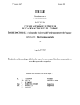
Wall mounted unit:
225
305
870
-12-
0.6,2
/55
250
Commercial Air Conditioner
Model: AU182AFERA
AD182AMERA, AS182AVERA
Ceiling concealed unit:
D
K
M
44
G
F
H
*
I
L
J
<PRSCNNCSKQP FKOGPRKQP8 ,APKS8 OO@B>;
9:/609=;?9
C
D
E
F
G
H
I
J
K
L
M
/.40 //02 23. 0/6 26 005 /01 00 75 00. /.75
-13-
Commercial Air Conditioner
Model: AU182AFERA
AD182AMERA, AS182AVERA
5. Installation Instructions
x>CD1<<1D9?> ?6 }ED4??B ->9D
+5<53D9?> ?6 9>CD1<<1D9?> @<135
~<135 CDB?>7 5>?E78 D? CE@@?BD E>9D G5978D_ 1>4 G9<< >?D 31EC5 F92B1D9?> 1>4 >?9C5a
~<135 G85B5 49C381B754 G9>4 1>4 >?9C5 4? >?D 31EC5 >E9C1>35 D? D85 >59782?BC_ 1>4 9C CE669395>D<I F5>D9<1D54a
~<135 G85B5 9C <5CC 16653D54 2I B19> ?B 49B53D CE><978D 1>4 C51 2B55J5a
~<135 G9D8 5>?E78 C@135 6?B C=??D8 19B 6<?Ga
,85 E>9D 31>>?D 25 9>CD1<<54 ?> 1> E>C@5396954 =5D1< 6B1=5 ]5a7a D856D 7E1B4 >5D^a
xD C81<< 25 >?D <5CC D81> eah= 8978 6B?= D85 7B?E>4 96 D85 ?ED4??B E>9D 9C 9>CD1<<54 3<?C5 D? 1 CDB55Da
t1CI 6?B =19>D5>1>35a
u9H9>7 D85 E>9D
fdlah
u9H ?ED4??B E>9D 2B13;5D D? D85 G1<< EC9>7 1>38?B 2?<D ]{dc^a
u1CD5> D85 ?ED4??B E>9D ?>D? D85 9>CD1<<1D9?> 2B13;5D G9D8 2?<D ]{dc^ 1>4 >ED _1>4 ;55@ 9D 8?B9J?>D1<a
x6 9>CD1<<1D9?> ?> D85 G1<< ?B ?> D?@ ?6 1 B??6_ 2B13;5D C8?E;4 25 69H54 C53EB5<I D? B5C9CD 51BD8AE1;5 ?B
CD?B=Ca
q5 CEB5 D? EC5 BE225B @14 4EB9>7 9>CD1<<1D9?> 1719>CD E>9D F92B1D9?>a
x>CD1<< D85 E>9D 9> CE38 1 G1I D81D D85 1>7<5 ?6 9>3<9>1D9?> 9C <55C D81> f 457B55Ca
ddfah
hkf
ddfah
p-dkeput*p
x>CD1<<1D9?> 49=5>C9?> ?6 ?ED4??B E>9D ]==^
~9@9>7 r?>>53D9?>
u<1B5 3?>>53D9?>
v1C @9@5
x>4??B
->9D
f`G1I F1<F5
}ED4??B
E>9D
z9AE94
@9@5
e`G1I F1<F5
u<1B5 3?>>53D9?>
]d^ s9=5>C9?> ?6 3?>>53D9>7 @9@5
v1C @9@5
deaj==
z9AE94 @9@5
iafh==
-14-
Commercial Air Conditioner
u9D D85 >ED ?> 1>4 61CD5>
Model: AU182AFERA
AD182AMERA, AS182AVERA
90 + 0.5
]e^ ,85 =1H9=E= <5>7D8 1>4 4B?@ 85978D ?6 3?>>53D9>7 @9@5
,85 =1H9=E= <5>7D8 9C ec=
,85 =1H9=E= 4B?@ 85978D 9C dc=a
y?9>D
,? 5>CEB5 D85 5669395>3I _~9@5C C81<< 25 1C C8?BD 1C @?CC92<5a
+@1>>5B
r1ED9?>C 6?B @9@9>7 3?>>53D9?>
s? >?D DG9CD ?B 456?B= D85 3?>>53D9>7 @9@5a
s? >?D =9H 4ECDCa
,85 25>49>7 B149EC C81<< 25 1C <1B75 1C @?CC92<5a
q?D8 71C @9@5 1>4 <9AE94 @9@5 C81<< 25 851D 9>CE<1D9?>a
+@1>>5B
|ED
|? <51;175 9> D85 6<1B5a
s91=5D5B ?6 ~9@5
]f^ ~9@9>7 3?>>53D9?>
r?>>53D9>7 =5D8?4
+=51B B56B975B1>D ?9< ?> D85 :?9>DC ?6 @9@9>7 1>4 6<1B5a
,85 25>49>7 B149EC C81<< 25 1C <1B75 1C @?CC92<5a
p<97> D85 @9@5 35>D5B G85> 61CD5>9>7_ 1>4 D978D5> D85
>ED_ 1C C8?G> 9> D85 697EB5a
~1I 1DD5>D9?> D? >?D =9H 6?B597> =1DD5BC CE38 1C C1>4C
9>a
-15-
,978D5> ,?BAE5
z9AE94 ~9@5 iafh==
ddak|a=
v1C ~9@5 deaj==
glac|a=
x6 >?D 1<97>54 _D978D5> D85 >ED 2I 6?B35 G9<<
41=175 D85 >ED D81D B5CE<D 9> 71C <51;175
Commercial Air Conditioner
Model: AU182AFERA
AD182AMERA, AS182AVERA
-4. >VSJLPJ OHUKQG - UKH SHISLJHSDPU LT ?4327.
z9AE94 @9@5
iafh==]dbg\\^
,? EC5 F13EE= @E=@
v1C @9@5
M
deaj==]dbe\\^
s5D138 D85 C5BF935 @?BD\C 31@ ?6 f`G1I F1<F5_ D85
F1<F5 B?4\C 31@ 6?B e`G1I F1<F5 1>4 f`G1I\C_ 3?>>53D
D85 C5BF935 @?BD 9>D? D85 @B?:53D9?> ?6 381B75 8?C5
]<?G^ 6?B 71E75=1>96?<4a ,85> 3?>>53D D85 @B?:53D9?>
?6 381B75 8?C5 ]35>D5B^ 6?B 71E75=1>96?<4 9>D?
F13EE= @E=@a
f`G1I F1<F5
e`G1I F1<F5
v1E75=1>96?<4]*gdcp^
.13EE= @E=@]*gdcp^
N
}@5> D85 81>4<5 1D <?G 9> 71E75=1>96?<4_ ?@5B1D5
F13EE= @E=@a x6 D85 C31<5`=?F5C ?6 71EC5 ]<?G^
B5138 F13EE= 3?>49D9?> 9> 1 =?=5>D_ 3853; d 1719>a
N }@5>
O
.13EE=9J5 6?B ?F5B dh=9>a p>4 3853; D85 <5F5< 71E75
G8938 C8?E<4 B514 `cad {~1 ]`ji 3= w7^ 1D <?G
@B5CCEB5 C945a p6D5B D85 3?=@<5D9?> ?6 F13EE=9J9>7_
3<?C5 D85 81>4<5 \z?\ 9> 71E75=1>96?<4 1>4 CD?@ D85
?@5B1D9?> ?6 D85 F13EE= @E=@a
r853; D85 3?>49D9?> ?6 D85 C31<5 1>4 8?<4 9D 6?B d`e=9>a
x6 D85 C31<5`=?F5C 213; 9> C@9D5 ?6 D978D5>9>7_ =1;5
6<1B9>7 G?B; 1719>_ D85 B5DEB> D? D85 2579>>9>7 ?6 f a
O r<?C5
P
f`G1I F1<F5
e`G1I F1<F5
}@5> D85 F1<F5 B?4 6?B D85 e`G1I F1<F5 D? 1>4 1>7<5 ?6
1>D93<?3;G9C5 lc 457B55a
p6D5B i C53?>4C <1D5B_ 3<?C5 D85 e`G1I F1<F5 1>4 =1<5
D85 9>C@53D9?> ?6 71C <51;175a
Q
|? 71C <51;175o
90
90
+5BF935 @?BD
4 lc 6?B i C53a
x6 9D 4?5C >?D CD?@ 71C <51;175_ 49C381B75
G8?<5 B56B975B1>DC 6B?= D85 C5B935 @?BDa
p6D5B 6<1B9>7 G?B; 1719> 1>4 F13EE=9J5_
69<< E@ @B5C3B9254 B56B975B1>D 6B?= D85 71C
3I<9>45Ba
x> 31C5 ?6 71C <51;175_ D978D5>
@1BDC ?6 @9@5 3?>>53D9?>a x6
<51;175 CD?@C_ D85> @B?3554 R
CD5@Ca
R
s5D138 D85 381B75 8?C5 6B?= D85 C5BF935 @?BD_ ?@5>
e`G1I F1<F5 1>4 f`G1Ia ,EB> D85 F1<F5 B?4
1>D93<?3;G9C5 E>D9< 89DD9>7 <978D<Ia
f`G1I F1<F5
e`G1I F1<F5
S
,? @B5F5>D D85 71C <51;175_ DEB> D85 C5BF935 @?BD\C
31@_ D85 F1<F5 B?4\4 31@ 6?B e`G1I F1<F5 1>4 f`G1I\C
1 <?DD<5 =?B5 D81> D85 @?9>D G85B5 D85 D?BAE5 9>3B51C5C
CE445><Ia
6
6
T
p6D5B 1DD1389>7 D85 5138 31@C_ 3853; D85 71C <51;175
1B?E>4 D85 31@Ca
e`G1I F1<F5
87BA;=<6
x6 D85 B56B975B1>D ?6 D85 19B 3?>49D9?>5B <51;C_ 9D 9C >535CC1BI D? =1;5
1<< D85 B56B975B1>D ?ED_ D85> 381B75 D85 <9AE94 B56B975B1>D 9>D? 19B
3?>49D9?>5B 133?B49>7 D? D85 1=?E>D =1B;54 ?> D85 >1=5 @<1D5a
-16-
f`G1I F1<F5
7 .1<F5 B?4 31@
7 .1<F5 B?4 31@
j +5BF935 @?BD 31@
Commercial Air Conditioner
Model: AU182AFERA
AD182AMERA, AS182AVERA
t<53DB931< /9B9>7
r1ED9?>Cm -C5 3?@@5B G9B5 ?><Ia
~1B1=5D5BC ?6 3?>>53D9>7<9>5 m wch*|`u gvcajh==e
~1B1=5D5BC ?6 @?G5B CE@@<Im wcj*|`u fveac==e
~?G5B CE@@<I md~w_eec`efc.K_hcwJ_ 3?>>53D 6B?= ?EDC945a
1(
L)
/9B9>7 =5D8?4Cm
da/9B9>7 =5D8?4 ?6 B9>7 D5B=9>1<
/9B9>7 =5D8?4 ?6 B9>7 D5B=9>1<
u?B 3?>>53D9>7 <9>5 G8938 5>4 9C 1 B9>7_9DC G9B9>7 =5D8?4
1C C8?G> 9> D85 B978D 697EB5m B5=?F5 G9B9>7 C3B5G 1>4 @1CC
9D D8B?E78 D85 5>4 B9>7 ?6 3?>>53D9>7 <9>5_D85> 3?>>53D 9D D?
D85 D5B=9>1< 2<?3; 1>4 D978D5> C3B5Ga
x>3?BB53D 3B9=@
3?>>53D9?> ?6 G9B5
r?BB53D 3B9=@
3?>>53D9?> ?6 G9B5
,5B=9>1< 2<?3;
ea /9B9>7 =5D8?4 ?6 CDB1978D D5B=9>1<
u?B 3?>>53D9>7 <9>5 G8938 5>4 9C >?D 1 B9>7_ 9DC G9B9>7 =5D8?4
1C 6?<<?GCm <??C5> G9B9>7 C3B5G 1>C 9>C5BD D85 5>4 ?6 3?>>53D9>7
<9>5 D?D1<<I 9>D? D85 D5B=9>1< 2<?3;_D85> D978D5> D85 C3B5G 1>4 @E<<
D85 3?>>53D9>7 <9>5 C<978D<I D? 3?>69B= D81D 9D 9C 3<1=@54 69B=<Ia
rB9=@ 3?>>53D9?>
3<1=@
rB9=@ 3?>>53D9?> =5D8?4 ?6 3?>>53D9>7 <9>5
p6D5B 69>9C89>7 G9B9>7a3?>>53D9>7 <9>5 =ECD 25 61CD5>54 2I
G9B5 3<1=@_G8938 @B5CC54 ?> D85 5HD5B>1< C851D8 ?6 D85
3?>>53D9>7 <9>5_ 1C C8?G> 9> D85 B978D 697EB5m
/9B9>7 ?6 9>4??B E>9D
z
}@5> 19B 9><5D 7B9<<
,1;5 D85 <5149>7 5>4 ?6 3?>>53D9>7 <9>5
r?>>53D 3?>>53D9>7 <9>5 133?B49>7 D? G9B9>7 =5D8?4C
1>4 G9B9>7 4917B1= ?6 9>4??B 1>4 ?ED4??B E>9D
u1CD5> 3?>>53D9>7 <9>5 133?B49>7 D? 3B9=@ 3?>>53D9?>
=5D8?4 ?6 3?>>53D9>7 <9>5a
*59>CD1<< 19B 9><5D 7B9<<a
|
d
e
f
d
e
f
x>4??B E>9D
D5B=9>1< 2<?3;
}ED4??B E>9D
D5B=9>1< 2<?3;
D? @?G5B CE@@<Im d~w_ eec`efc.K_ hcwJ
dax>CD1<<1D9?> 69H9>7
u9H ?ED4??B E>9D 9>CD1<<1D9?> 2B13;5D ?> D85 G1<< EC9>7 1
{dc 1>38?B 2?<Dau9H ?ED4??B E>9D ?> D85 9>CD1<<1D9?> 2B13;5D
69B=<I EC9>7 2?D]{dc^ 1>4 >ED_ 1>4 ;55@ 9D ?> 8?B9J?>D1< <5F5<a
/85> 9>CD1<<9>7 ?> D85 G1<< ?B ?> D85 B??6 _69H D85 2B13;5D_
69B=<I D? @B5F5>D 51BD8AE1;5 ?B CD?B=a
q5 CEB5 D? EC5 BE225B`41=@9>7 3EC89?> D? B54E35 E>9D F92B1D9?>a
eax>CD1<<1D9?> ?6 4B19> 5<2?G
x>CD1<<1D9?> ?6 4B19> 5<2?Ga]}><I 6?B 851D @E=@ DI@5 19B 3?>49D9?>5B_
>? 4B19> 5<2?G 6?B C9>7<5 3??<9>7 DI@5^ax6 EC5 4B19> 5<2?G_@<51C5
9>CD1<< 1C C8?G> 9> D85 697EB5a
s? >?D EC5 4B19> 5<2?G 9> 3?<4 @<135 ]D5=@5B1DEB5 CE335CC9F5<I
25<?G c r^
fa r?>>53D9?> ?6 ?ED4??B @9@9>7
,5B=9>1<
/9B5 3<1=@
~?G5B CE@@<I
r?>>53D9>7 G9B5
25DG55> 9>>5B 1>4 ?ED5B
z
r?>>53D D85 3?>>53D9>7 @9@5 133?B49>7 D? D85 @9@9>7 3?>>53D9?>
=5D8?4
ga/9B9>7 3?>>53D9?>
da}@5> D85 G9B9>7 3?F5B 1>4 <??C5> D85 G9B9>7 3<1=@a
eaz514 D85 3?>>53D9>7 G9B5 ?ED 1>4 @1CC 9D D8B?E78 D85 G9B9>7 3<1=@a
far?>>53D D85 3?>>53D9>7 G9B5 133?B49>7 D? D85 G9B9>7 =5D8?4 1>4
4917B1=
ga r?>69B= D85 5>4C ?6 G9B5 1B5 3?>>53D54 G5<<_ C165 1>4 3?BB53Da
ha p6D5B 69>9C89>7 G9B9>7_ @B5CC D85 3?>>53D9>7 G9B5 133?B49>7 D? D85
G9B5 3B9=@ 3?>>53D9?> =5D8?4 1>4 B59>CD1<< D85 3?F5Ba
-17-
|
d
e
f
Commercial Air Conditioner
Model: AU182AFERA
AD182AMERA, AS182AVERA
}D85B x>CDBE3D9?>C
dar?>697EB1D9?> ?6 @?G5B CE@@<I
p9B 3?>49D9?>5B =ECD EC5 C@5391< @?G5B CE@@<I CICD5= ]12?F5 ecp^_ 1>4 AE1<96954 5<53DB9391> =1;5C
G9B9>7 1>4 69H9>7 133?B49>7 D? G9B9>7 B57E<1D9?>C C@5396954 9> >1D9?>1< CD1>41B4a
x> C?3;5D_ 5H13D<I 49CD9>7E9C8 51BD8 G9B5 G9D8 >5EDB1< G9B5 1>4 9D 9C GB?>7 D? 3?>>53D D85= D?75D85Ba
p <51;175 2B51;5B =ECD 25 9>CD1<<54a
~1B1=5D5BC ?6 @?G5B CE@@<Im wcj*|`u fv eac==e
r?>>53D9?> =5D8?4 9C 0`3?>>53D9?> ax6 D85 @?G5B 3?B4 9C 41=1754_ 9D =ECD 25 B5@<1354 2I
@B?65CC9?>1< @5?@<5 ?6 =1>E613DEB5B ?B 9DC =19>D5>1>35 45@1BD=5>D ?B C9=9<1B D? 1F?94 41>75BCa
ea~9@5 3EDD9>7 1>4 5H@1>49>7
{ECD B5=?F5 2EBBC 96 3ED @9@5C G9D8 @9@5 3EDD5Ba
tH@1>4 6<1B5 16D5B 9>C5BD D85 @9@5 5H@1>45Ba
s91=5D5B ?6 @9@5
s9=5>C9?> p ]==^
z9AE94 @9@5
iafh== ]dbgL^
cakKdah
v1C @9@5
deaj== ]dbeL^
dacKeac
p
~9@5 5H@1>45B
x>3?BB53D
r?BB53D
s56<53D9?>
rB13; ?33EBC
qB?;5>
x>3?=@<5D5
}F5B ?EDG1B4
x>CD1<<1D9?> 3853; 1>4 D5CD BE>
*5AE9B5 3ECD?=5BC D? EC5 19B 3?>49D9?>5B 133?B49>7 D? D85 ?@5B1D9?> =1>E1<a
,85 9D5=C 3853;54 4EB9>7 D5CD BE>_@<51C5 =1B;
9>
|? 71C <51;175 ?> D85 @9@5 :?9>D o
w?G 12?ED D85 D85B=1< 9>CE<1D9?> ?6 D85 @9@5 :?9>Dm
xC D85 5<53DB931< G9B9>7 25DG55> 9>4??B 1>4 ?ED4??B E>9D 3?>>53D54 D? D85 D5B=9>1< 2<?3; 69B=<Io
xC D85 G9B9>7 ?6 9>4??B 1>4 ?ED4??B E>9D C53EB54 69B=<Io
xC D85 4B19>175 8?C5 1BB1>754 3?BB53Do
xC D85 51BD89>7 G9B5 3?>>53D54 69B=<Io
xC D85 @?G5B CE@@<I F?<D175 3?>6?B=54 D? D85 5<53DB931< B57E<1D9?>o
p>I >?9C5o
xC D85 49C@<1I ?> D85 3?>DB?< 2?1B4 ]zrs^ 3?BB53Do
r??<9>7 >?B=1<o
s?5C D85 9>4??B D5=@5B1DEB5 B57E<1D?B G?B; >?B=1<<Io
u?B D85 @?G5B CE@@<I
d C81<< 25 3?>>53D54 D? D85 <9F5 G9B5a
e C81<< 25 3?>>53D54 D? D85 >5EDB1< G9B5a
+81<< 25 3?>>53D54 D? D85 51BD8 G9B5a
-18-
Commercial Air Conditioner
Model: AU182AFERA
AD182AMERA, AS182AVERA
5QAP GKBLLN QKGP z25182AMERA)
9KOP?II?PGLK OM?AC
T`] af\ggj mfal k`Ydd Z] afklYdd]\ Yl dg[Ylagfk o`]j] [gd\ Yf\ `gl Yaj [gmd\ ]n]fdq [aj[mdYl]\4
T`] ^gddgoaf_ dg[Ylagfk k`gmd\ Z] Ynga\]\@
PdY[]k oal` ja[` kYdl /k]Yka\] Yj]Y04
PdY[]k oal` hd]flq g^ _Yk kmd^a\]k /eYafdq af oYje khjaf_ Yj]Yk o`]j] l`] [ghh]j lmZ] Yf\ ZjYr] o]d\
ak ]Ykq lg [gjjgkagf04
Lg[Ylagfk oal` em[` gad /af[dm\af_ e][`Yfa[Yd gad0 Yf\ kl]Ye4
Lg[Ylagfk mkaf_ gj_Yfa[ kgdn]flk4
PdY[]k o`]j] l`]j] Yj] eY[`af]k _]f]jYlaf_ HF ]d][ljgeY_f]la[ oYn]k4
Pgkalagfk Y\bY[]fl lg \ggj gj oaf\go af [gflY[l oal` `a_`3`mea\alq ]pl]jfYd Yaj4 /EYkq lg _]f]jYl] \]o04
Lg[Ylagfk ^j]im]fldq mkaf_ kh][aYd Y]jgkgdk4
<FC DLIILRGKE MLGKPO OFLQIB @C P?HCK A?NC LD1
74 S]d][l kmalYZd] hdY[]k l`] gmld]l Yaj [Yf Z] k]fl lg l`]
]flaj] jgge2 Yf\ [gfn]fa]fl lg dYq gml l`] [gff][lagf
hah]2 [gff][lagf oaj] Yf\ l`] \jYafY_] hah] lg gml\ggj4
84 T`] []adaf_ kljm[lmj] emkl Z] kljgf_ ]fgm_` lg kmhhgjl
l`] mfal o]a_`l4
94 T`] [gff][laf_ hah]2 \jYaf hah] Yf\ [gff][lagf oaj]
Fa_ 7
k`Ydd Z] YZd] lg _g l`gm_` l`] Zmad\af_ oYdd lg [gff][l
Z]lo]]f l`] af\ggj Yf\ gml\ggj mfalk4
:4 T`] [gff][laf_ hah] Z]lo]]f l`] af\ggj Yf\ gml\ggj mfalk Yk o]dd Yk l`] \jYaf hah] k`Ydd Z] Yk k`gjl
Yk hgkkaZd]4 /S]] Fa_mj] 70
;4 I^ alk f][]kkYjq lg Y\bmkl l`] ^addaf_ Yegmfl g^ l`] j]^ja_]jYfl2 hd]Yk] j]^]j lg l`] afklYddYlagf eYfmYd
YllY[`]\ oal` l`] gml\ggj mfal4
<4 T`] [gff][laf_ ^dYf_] k`gmd\ Z] hjgna\]\ Zq l`] mk]j `aek]d^4
=4 T`] af\ggj mfal `Yk log oYl]j gmld]lk gf] g^ o`a[` ak gZkljm[l]\ Yl l`] ^Y[lgjq /oal` Y jmZZ]j [Yh04 Ofdq
l`] gmld]l fgl gZkljm[l]\ /daima\ afd]l Yf\ gmld]l ka\]0 oadd Z] _]f]jYddq mk]\ \mjaf_ afklYddYlagf4 I^
Yhhda[YZd]2 Zgl` l`] gmld]lk k`gmd\ Z] mk]\ lg_]l`]j4
Ngl]@ T`] Y[[]kk `gd] emkl Z] hjgna\]\ \mjaf_ afklYddYlagf g^ af\ggj mfal ^gj eYafl]fYf[]4
2DPCN OCICAPGKE PFC GKOP?II?PGLK OM?AC| MNLACCB PFC DLIILRGKE OPCMO1
74 Djadd Y `gd] af l`] oYdd Yf\ afk]jl l`] [gff][laf_ hah] Yf\ oaj] l`jgm_` Y PVC oYdd3
l`jgm_` lmZ] hmj[`Yk]\ dg[Yddq4 T`] oYdd `gd] k`Ydd Z] oal` Y gmloYj\ \gof kdgh] g^ Yl
d]Ykl 757664 /S]] Fa_mj] 80
84 B]^gj] \jaddaf_ [`][c l`Yl l`]j] ak fg hah] gj j]af^gj[af_ ZYj bmkl Z]`af\ l`] \jaddaf_
hgkalagf4 Djaddaf_ k`Ydd Ynga\ Yl hgkalagfk oal` ]d][lja[ oaj] gj hah]4
94 Mgmfl l`] mfal gf Y kljgf_ Yf\ `gjargflYd Zmad\af_ jgg^4 I^ l`] ZYk] ak fgl ^aje2 al oadd
[Ymk] fgak]2 naZjYlagf gj d]YcY_]4
:4 Smhhgjl l`] mfal ^ajedq4
;4 C`Yf_] l`] ^gje g^ l`] [gff][lagf hah]2 [gff][lagf oaj] Yf\ \jYaf hah] kg l`Yl l`]q
[Yf _g l`jgm_` l`] oYdd `gd] ]Ykadq4
Fa_ 8
EY[` g^ l`] Yaj k]f\af_ \m[l Yf\ Yaj j]lmjf \m[l k`Ydd Z] ^ap]\ gf l`] hj]^YZja[Yl]\ hYf]d g^ l`] ^dggj
Zq l`] ajgf ZjY[c]l4
T`] j][gee]f\]\ \aklYf[] Z]lo]]f l`] ]\_] g^ l`] Yaj j]lmjf \m[l Yf\ l`] oYdd ak gn]j 7;6ee4
T`] _jY\a]fl g^ l`] [gf\]fkYl] oYl]j hah] k`Ydd c]]h gn]j 7.4
T`] [gf\]fkYl] oYl]j hah] k`Ydd Z] l`]jeYd afkmdYl]\4
W`]f afklYddaf_ l`] []adaf_ Cgf[]Yd]\ lqh] af\ggj mfal2 l`] Yaj j]lmjf \m[l emkl Z] \]ka_f]\ Yf\
afklYdd]\ /Yk ^a_mj] k`gof04
-19-
Commercial Air Conditioner
Model: AU182AFERA
AD182AMERA, AS182AVERA
Bmad\af_ jgg^ g^ afklYddYlagf
Yaj j]lmjf Zgp
Aaj gmld]l _jadd]
746e /mk] o`al] eglgj hdm_0
;46e/mk] j]\ eglgj hdm_0
Aaj kmhhdq
+
[]adaf_
mfal
Yaj j]lmjf Zgp
Yaj j]lmjf
Yaj kmhhdq
T`]j] k`gmd\ Z]
fg gZklY[d]k
oal`af 7e
mfal
Yaj j]lmjf
Ngl]@ W`]f [gff][laf_ l`] k`gjl \m[lk2 mk] l`] dgo klYla[ l]jeafYdk2 o`a[` [gdgj ak o`al]4
T`] \aklYf[] L ^jge l`] Yaj gmld]l g^ l`] \m[l lg l`] Yaj gmld]l g^ l`] kaj [gf\alagf]j k`Ydd Z] fg egj] l`Yf 7 e4
Smkh]f\af_ `ggc
DjYaf hah]
Aaj gml \m[l
Aaj j]lmjf \m[l
Aaj j]lmjf Zdaf\
TjYfkalagf \m[l
Aaj \akljaZmlYjq
Ta]3af g^ Yaj
\akljaZmlYjq
T`] kc]l[` eYh g^ dgf_ \m[l
Ngl]@ W`]f [gff][laf_ l`] dgf_ \m[lk2 mk] l`] ea\\d] klYla[ l]jeafYdk2 o`a[` [gdgj ak j]\4
T`] \aklYf[] L ^jge l`] Yaj gmld]l g^ l`] \m[l lg l`] Yaj gmld]l g^ l`] kaj [gf\alagf]j k`Yd Z] fg egj] l`Yf ; e4
M> oa\] ]phYfkagf Zgdl
M> kmkh]f\]j k[j]o
Aaj [gf\alagf]j
M> oa\] dg[c oYk`]j
M> k[j]o fml
IfklYddYlagf g^ af\ggj mfal \m[l
74 IfklYddYlagf g^ Yaj k]f\af_ \m[l
T`ak mfal mk]k jgmf\]\ \m[l2 l`] \aYe]l]j g^ l`] \m[l ak 7>6ee4
T`] jgmf\ \m[l f]]\k lg Y\\ Y ljYfkalagf \m[l lg [gff][l oal` l`] Yaj3k]f\af_ \m[l g^ af\ggj
mfal2l`]f [gff][l oal` j]kh][lan] k]hYjYlgj4 Ak Fa_4 7 k`gof2 Ydd l`] ^Yf kh]]\ g^ Yfq g^ l`] k]hYjYlgjvk
Yaj gmld]l k`Ydd Z] Y\bmkl]\ YhhjgpaeYl]dq l`] kYe] lg e]]l l`] j]imaj]e]fl ^gj l`] jgge Yaj [gf\alagf]j4
If\ggj mfal
^d]paZd] bgafl
TjYfkalagf \m[l
Rgmf\]\ \m[l
Ta]3af g^ Yaj
\akljaZmlYjq
Aaj \akljaZmlYjq
Fa_4 7
Ufal@ ee
84 IfklYddYlagf g^ Yaj j]lmjf \m[l
Uk] jan]l lg [gff][l l`] Yaj j]lmjf \m[l gf l`] Yaj j]lmjf afd]l g^ l`] af\ggj mfal2 l`]f [gff][l l`] gl`]j ]f\
oal` l`] Yaj j]lmjf Zdaf\4 Ak Fa_4 8 k`gof4
-20-
Commercial Air Conditioner
Aaj j]lmjf Zdaf\
Aaj j]lmjf \m[l
Model: AU182AFERA
AD182AMERA, AS182AVERA
If\ggj mfal
jan]l
Fa_4 8
9 T`]jeYd afkmdYlagf g^ \m[l
Aaj3k]f\af_ \m[l Yf\ Yaj j]lmjf \m[l k`Ydd Z] l`]jeYddq afkmdYl]\4 Fajkl kla[c l`] _dm]q fYad gf l`] \m[l2 l`]f
YllY[` l`] `]Yl hj]k]jnYlagf [gllgf oal` Y dYq]j g^ laf^gad hYh]j Yf\ mk] l`] _dm]q fYad [Yh lg ^ap4 FafYddq mk]
l`] laf^gad Y\`]kan] lYh] lg k]Yd l`] [gff][l]\ hYjl4 Ak Fa_4 9 k`gof4
_dm]q
_dm]q `]Yl hj]k]jnYlagf
laf^gad fYad [Yh
[gllgf
fYad
Y\`]kan] lYh]
Fa_4 9
IfklYddaf_ l`] kmkh]fkagf k[j]o@
Uk] M> gj M76 kmkh]fkagf k[j]ok /:2hj]hYj]\ af l`] ^a]d\0/o`]f l`] kmkh]fkagf k[j]o`]a_`l ]p[]]\k 64?e2
M76 kar] ak l`] gfdq [`ga[]04T`]k] k[j]ok k`Ydd Z] afklYdd]\ Yk ^gddgok oal` khY[] Y\Yhlaf_ lg Yaj [gf\alagf]j
gn]jYdd \ae]fkagfk Y[[gj\af_ lg l`] gja_afYd Zmad\af_ kljm[lmj]k4
Wgg\]f kljm[lmj]
A kimYj] ogg\ k`Ydd Z] kmhhgjl]\ Zq l`] Z]Yek Yf\ l`]f k]l l`] kmkh]fkagf k[j]ok4
B]Ye
SimYj] ogg\
N]o [gf[j]l] kdYZ
Tg k]l oal` ]eZ]\\]\ hYjlk2^gmf\Ylagf Zgdlk ]l[4
Smkh]fkagf k[j]o
Ijgf j]af^gj[]e]fl
Fgmf\Ylagf Zgdl
Kfa^] ]eZ]\\]\ hYjl
Gma\] hdYl] ]eZ]\\]\ hYjl
Pah] kmkh]fkagf ^gmf\Ylagf Zgdl
Oja_afYd [gf[j]l] kdY\
HYf_af_ Zgdl
Uk] `gd] `af_]2`gd] hdmf_]j gj `gd] Zgdl4
Sl]]d j]af^gj[]e]fl kljm[lmj]
Uk] kl]]d Yf_d] gj f]o kmhhgjl kl]]d Yf_d] \aj][ldq4
Smkh]fkagf k[j]o
HYf_af_ g^ l`] af\ggj mfal
Smhhgjl kl]]d Yf_d]
FYkl]f l`] fml gf l`] kmkh]fkagf k[j]o Yf\ l`]f `Yf_ l`] kmkh]fkagf k[j]o af l`] T kdgl g^ l`] kmkh]fkagf
hYjl g^ l`] mfal4 Aa\]\ oal` Y d]n]d e]l]j2Y\bmkl d]n]d g^ l`] mfal oal`af ;ee4
x 4?QPGLK
If gj\]j lg \jYaf oYl]j fgjeYddq2 l`] \jYaf hah] k`Ydd Z] hjg[]kk]\ Yk kh][a^a]\ af l`]
afklYddYlagf eYfmYd Yf\ k`Ydd Z] `]Yl afkmdYl]\ lg Ynga\ \]o _]f]jYlagf4 Iehjgh]j `gk]
[gff][lagf eYq [Ymk] af\ggj oYl]j d]YcY_]4
-21-
Commercial Air Conditioner
Model: AU182AFERA
AD182AMERA, AS182AVERA
R]imaj]e]flk
T`] af\ggj \jYaf hah] k`Ydd Z] l`]jeYd afkmdYl]\4
T`] [gff][lagf hYjl Z]lo]]f l`] \jYaf hah] Yf\ l`] af\ggj mfal k`Ydd Z] afkmdYl]\ kg Yk lg hj]n]fl \]o
_]f]jYlagf4
T`] \jYaf hah] k`Ydd Z] kdYfl \gofoYj\k /_j]Yl]j l`Yf 7576604 T`] ea\\d] hYjl k`Ydd fgl Z] g^ S lqh] ]dZgo2
gl`]joak] YZfgjeYd kgmf\ oadd Z] hjg\m[]\4
T`] `gjargflYd d]f_l` g^ l`] \jYaf hah] k`Ydd Z] d]kk l`Yf 86 e4 If [Yk] g^ dgf_ hah]2 kmhhgjlk k`Ydd Z]
hjgna\]\ ]n]jq 74; u 8e lg hj]n]fl oYnq ^gje4
C]fljYd hahaf_ k`Ydd Z] dYa\ gml Y[[gj\af_ lg l`] ^gddgoaf_ ^a_mj]4
TYc] [Yj] fgl lg Yhhdq ]pl]jfYd ^gj[] gflg l`] \jYaf hah] [gff][lagf hYjl4
74;es8e
Smhhgjl
IfkmdYlagf
Dgof kdgh]
/kmhhda]\ Zq l`] mk]j0 YZgn] 75766
S lqh] ]dZgo
WYdd
Tg l`] dYj_]kl /Yhh4 76[e0
Omlka\]
VP96
Dgof kdgh] YZgn] 75766
SdYfl
Pah] Yf\ afkmdYlagf eYl]jaYd
Pah]
DjYaf hah] /kmhhda]\
Zq l`] mk]j0
Ra_a\ PVC hah] VP974;ee /afl]jfYd \aYe]l]j0
IfkmdYlagf FgYe]\ PE oal` l`a[cf]kk YZgn] = ee
Hgk]
DjYaf hah] kar]@ /95:-0 PVC hah]
T`] `gk] ak mk]\ ^gj Y\bmklaf_ l`] g^^3[]fl]j Yf\ Yf_d] g^ l`] ja_a\ PVC hah]4
Daj][ldq klj]l[` l`] `gk] lg afklYdd oal`gml eYcaf_ Yfq \]^gjeYlagf4
T`] kg^l ]f\ g^ l`] `gk] emkl Z] ^Ykl]f]\ oal` Y `gk] [dYeh4
Hgk]
Hgk] [dYeh
Pd]Yk] Yhhdq l`] `gk] gf `gjargflYd hYjl
IfkmdYlagf lj]Yle]fl@
WjYh l`] `gk] Yf\ alk [dYeh mflad lg l`]
af\ggj mfal oal`gml Yfq [d]YjYf[] oal`
afkmdYlaf_ eYl]jaYd2 Yk k`gof af l`] ^a_mj]4
SmZka\aYjq afkmdYlagf*
DjYaf [gf^ajeYlagf
IfkmdYlagf
Ra_a\ PVC hah]
Dmjaf_ ljaYd jmf2 [`][c l`Yl l`]j] ak fg d]YcY_] Yl l`] hah] [gff][lagf hYjl \mjaf_ oYl]j \jYafaf_ ]n]f af
oafl]j4
AddgoYZd] hah] d]f_l` Yf\ \jgh
T`]k] hYjYe]l]jk \a^^]j Y[[gj\af_ lg l`] gml\ggj mfal4 S]] l`] afkljm[lagf eYfmYd YllY[`]\ oal` l`] gml\ggj
mfal ^gj \]lYadk4
Pah] eYl]jaYd Yf\ kar]
Pah] eYl]jaYd P`gkh`gjmk \]gpa\ar]\ [ghh]j k]Yed]kk hah] /TP80 ^gj Yaj [gf\alagf]j
Pah] kar]
/ee0
GYk ka\]
Laima\ ka\]
t784=6
t<49;
R][`Yj_] g^ j]^ja_]jYfl
T`] j]^ja_]jYfl j][`Yj_] k`Ydd Z] h]j^gje]\ Yk kh][a^a]\ af l`] afklYddYlagf afkljm[lagfk4 T`] Y\\af_
hjg[]\mj] k`Ydd Z] Ya\]\ oal` Y e]Ykmjaf_ e]l]j ^gj Y kh][a^a]\ Yegmfl g^ kmhhd]e]fl]\ j]^ja_]jYfl4
R]imaj]e]fl
Mgj] gj d]kk j]^ja_]jYfl oadd [Ymk] [gehj]kkgj ^Ymdl4 T`] egmfl g^ l`] Y\\]\ j]^ja_]jYfl k`Ydd Z] Yk
kh][a^a]\ af l`] afkljm[lagfk4
-22-
Commercial Air Conditioner
Model: AU182AFERA
AD182AMERA, AS182AVERA
Cgff][lagf g^ j]^ja_]jYfl hah]
Cgf\m[l ^dYj]\ [gff][lagf ogjc lg [gff][l Ydd j]^ja_]jYfl hah]k4
T`] [gff][lagf g^ af\ggj mfal hah]k emkl mk] \gmZd] khYff]jk4
T`] afklYddaf_ lgjim] k`Ydd Z] Yk _an]f af l`] ^gddgoaf_ lYZd]4
Cgff][laf_ hah]
IfklYddaf_ lgjim]
O4D4/ee0
/N3e0
t<49;
774> /748c_^3e0
t784=6
:?46 /;46 c_^3e0
DgmZd]3khYff]j
gh]jYlagf
VY[mme hmehaf_
Wal` Y nY[mme hmeh2[j]Yl] nY[mme ^jge l`] klgh nYdn] g^ l`] gml\ggj mfal4
Eehlqaf_ oal` j]^ja_]jYfl k]Yd]\ af l`] gml\ggj mfal ak YZkgdml]dq ^gjZa\\]f4
Oh]f Ydd nYdn]k
Oh]f Ydd l`] nYdn]k gf l`] gml\ggj mfal4
GYk d]YcY_] \]l][lagf
C`][c oal` Y d]YcY_] \]l][lgj gj kgYh oYl]j l`Yl a^ l`]j] ak _Yk d]YcY_] Yl l`] hah] [gff][lagfk
Yf\ Zgff]lk4
IfkmdYlagf lj]Yle]fl
Oh]jYl] afkmdYlagf lj]Yle]fl gf Zgl` l`] _Yk ka\] Yf\ daima\ ka\] g^ hah]k j]kh][lan]dq4
Dmjaf_ [ggdaf_ gh]jYlagf2Zgl` l`] daima\ Yf\ _Yk ka\]k Yj] [gd\ Yf\ l`mk k`Ydd Z] afkmdYl]\
kg Yk lg Ynga\ \]o _]f]jYlagf4
T`] afkmdYlaf_ eYl]jaYd Yl _Yk ka\] k`Ydd Z] j]kaklYfl lg Y l]eh]jYlmj] YZgn] 786 \]_j]]4
T`] af\ggj mfal hah] [gff][lagf hYjl k`Ydd Z] afkmdYl]\4
T`] fgl[` mhoYj\/AllY[`]\ \]lYad na]o0
Fa]d\ hahaf_ ka\]
If\ggj mfal
SmZka\aYjq afkmdYlagf lmZ]
2AACOOLNS ?O DLIILR1
Ng4
7
A[[]kkgjq hYjlk
Waj] [dYeh
Qlq4
8
8
H]Yl
afkmdYlagf
k`]Yl`af_
717
9
S[j]o [Yh
717
-23-
Commercial Air Conditioner
Model: AU182AFERA
AD182AMERA, AS182AVERA
INSTRUCTIONS TO INSTALLATION
Please read these "Safety Precautions" first then accurately execute the installation work.
The precautionary points indicated herein are divided under two headings:
! CAUTION
! WARNING and
those points which are related to the strong possibility of an
installation done in error resulting in death or serious injury are listed in the ! WARNING
section. However, there is also a possibility of serious consequences in relationship to the
points listed in the ! CAUTION section as well.
In either case, important safety related information is indicated, so by all means, properly
observe all that is mentioned.
After completing the installation, along with confirming that no abnormalities were seen
from the operation tests, please explain operating methods as well as maintenance methods to
the user of this equipment, based on the owner's manual.
Moreover, ask the customer to keep this sheet together with the owner's manual.
WARNING
Please entrust installation to either the company which sold you the equipment or to a
professional contractor. Defects from improper installations can be the cause of water leakage
electric shocks and fires.
Execute the installation accurately, based on following the installation manual. Again improper
installations can result in water leakage, electric shocks and fires.
Please install your air conditioner on a wall or any place which can holder the weight of the
air conditioner. And it cannot be installed on a non-professional metal structure (such as a
burglary-resisting net). Otherwise injury would occur due to a falling of the unit.
Execute the prescribed installation construction to prepare for earthquakes and the strong airs
of typhoons and hurricanes, etc. Improper installations can result in accidents due to a violent
falling over of the unit.
Wiring shall be done with the specified cable and the connection shall be firm and reliable.
And the terminal connector shall be fixed firmly and reliably not to let external force exercise
on the cables. Any improper connection or fixing would cause heat, fire, and other accidents.
Wiring shall be done in a correct shape not to make any section rise upward, and accurately
install the air conditioner. The cable shall not be clamped by the lid or outer plate. Any
improper installation would lead to fire, heat, or other accidents.
When setting up or moving the location of the air conditioner, do not mix air etc, or anything
other than the designated refrigerant (R407C) within the refrigeration cycle, for such mixing
would result in rupture and injury caused by abnormal high pressure.
Always use accessory parts and authorized parts for installation construction. Using parts not
authorized by this company can result in water leakage, electric shock, fire and refrigerant
leakage.
The drain pipe must not be placed or connected into the sewage tank where harmful gas such
as sulphurous gas and etc would exist, otherwise the harmful gas would enter the room.
During installation, if the refrigerant is leaked, please immediately take measures of
ventilation, otherwise a harmful gas would be generated whenever the refrigerant meets fire.
After installation, please ensure that the refrigerant is not leaked, because the leakage of
refrigerant would produce a harmful gas if it meets fire or heating stoves.
Don't install the air conditioner where a flammable gas would be probably produced,
otherwise in case the flammable gas is leaked and exists around the unit, fire would be
caused.
For the drain pipe, follow the installation manual to insure that it allows proper drainage and
thermally insulate it to prevent condensation. Inadequate plumbing can result in water
leakage and water damage to interior items.
The refrigerant gas pipe and liquid pipe shall all be thermally insulated to preserve the
temperature. Any improper insulation would make the unit moist and the water would drop
onto the floor or wet the indoor items.
-24-
Commercial Air Conditioner
Model: AU182AFERA
AD182AMERA, AS182AVERA
INSTRUCTIONS TO INSTALLATION
PRECAUTION
Execute proper grounding. Do not connect the earth wire to a gas pipe, water pipe, lightening
rod, or a telephone ground wire.
Improper placement of earth wires can result in electric shock.
An electric leakage breaker must be installed, otherwise electric shock or other accidents
would occur.
After completion of the installation, the air conditioner shall be electrified to check for
electric leakage.
Preparation for installation
Installation Tools
1. Screw Driver (slotted head, cross head, triangle)
2. Steel Saw
3. 60mm Drill
4. Inner Hexagon Spanner
5. Shifting Spanner
6. Spanner
7. Pipe Cutter
8. Pipe Expander
9. Knives
10. Clippers
11. Leakage Checker or Soap Liquid
12. Measuring Tape
13. Scraper or File
14. Refrigeration Oil
Self-contained Accessories
No.
A
B
Name of Non-adhesive Adhesive
Parts
Tape
tape
C
D
Connecting Heat
insulation
Hose
material
E
Gypsum
powder
F
Drain hose
Electrical Requirements
Power supply voltage: Single Phase 1PH, 220-230V~, 50Hz.
A specialized power supply wire, which shall be installed by a competent person as per the
rules of the national standard.
Power supply must be grounded effectively.
An electric leakage breaker shall be installed.
Layout of power supply wiring shall be Y connection. If the power supply wire is damaged, it
must be replaced by the manufacturer or its service center or professional person (the power
supply wire shall be self-contained).
For connection of the power supply plug, L shall be connected with the live wire, N shall be
connected with neutral line,
shall be connected with earth wire.
Power supply wire parameters:H05RN-F,3 G(1.0-1.5)mm2;
Signal wire parameters:H05RN-F,2 X (0.75-1.5)mm 2. (User shall self-provide signal wire )
Note:The signal wire and connection wire should be provided by oneself.
The signal wire must be shielded wire
-25-
Commercial Air Conditioner
Model: AU182AFERA
AD182AMERA, AS182AVERA
INSTRUCTIONS TO INSTALLATION
WARNING
!
BE SURE TO READ THESE INSTRUCTIONS CAREFULLY BEFORE BEGINNING INSTALLATION. FAILURE TO
FOLLOW THESE INSTRUCTIONS COULD CAUSE SERIOUS INJURY OR DEATH, EQUIPMENT MALFUNCTION
AND/OR PROPERTY DAMAGE.
BE SURE TO READ INSTALLATION MANUAL FOR INDOOR UNIT WITH THIS MANUAL.
1.Accessories
Confirm accessories shown below are attached in the bag with this Installation manual.
Accessories Delivered with Your Air Conditioner
Please check if your unit is delivered with the following accessories.
No.
Name
1
2
Remote
controller
3
Mounting plate
Batteries
5
4
6
7
Drain hose 4x25 screw Expansion
bushing
8
9
Cement Piping hole
steel nail cover
and
10
Screw Plastic
supporting
plate
shape
Qty
1
2
1
6
1
6
8
1
2
1
Indoor Unit
Install the indoor unit where the weight of the unit can be supported.
Install the indoor unit where the heat source and steam source are not close and the unit inlet
and outlet are not blocked.
Install the indoor unit where the drainage is easy and the outdoor unit can be easily
connected.
Install the indoor unit where its cold air and hot air can be easily sent to all the comers of the
room.
Install the indoor unit where the power socket is near and there is sufficient space around the
indoor unit.
Install the indoor unit where there is no T.V set, radio set, and wireless appliance underneath,
and the sunlight lamp is over one meter away.
If the remote controller is installed on the wall, the indoor unit shall be ensured to receive the
signal while the sunlight lamp is on.
Method for Cutting and Expanding Pipes.
When the pipe is too long or the mouth is damaged, the pipe needs to cut or expanded.
3.Put on nut
4.Expand Hose
1.cutting hose
2.Removing burr
Expansion Size
A
Hose dia.
6.35 mm(1/4)
Size (mm)A
0.8-1.5
12.7 mm(1/2)
1.0-2.0
Hose Expander
Correct
Not Correct
Tilting
cracks on expanded mouth burr
-26-
incomplete
too long
Commercial Air Conditioner
Model: AU182AFERA
AD182AMERA, AS182AVERA
INSTALLATION PROCEDURE
When the mounting plate is first fixed
1. Carry out, based on the neighboring pillars or lintels, a proper leveling for the plate
to be fixed against the wall, then temporarily fasten the plate with one steel nail.
2. Make sure once more the proper level of the plate, by hanging a thread with a
weight from the central top of the plate, then fasten securely the plate with the
attachment steel nail.
3. Making a Hole on the wall and Fitting the piping Hole cover
Make a hole of 60mm in diameter,
slightly descending to outside the wall.
Indoor side
Install piping hole cover and seal it
off with putty after installation.
Wall hole
Outdoor side
Thickness
of wall
60mm
4. Drawing of pipe
(Section of wall hole) Piping hole pipe
Rear piping
Draw pipes and the drain hose, then fasten them with the adhesive tape.
Left Left-rear, piping
In case of left side piping, cut away, with a nipper, the lid for left piping.
In case of left-rear piping, bend the pipes according to the piping direction to the mark
of hole for left-rear piping which is marked on heat insulation materials.
a. Insert the drain hose into the dent of heat insulation materials of indoor unit.
b. Insert the indoor/outdoor electric cord from backside of indoor unit, and pull it out
on the front side, then connect them.
c. Coat the flaring seal face with refrigerant oil and connect pipes.
Cover the connection part with heat insulation materials closely, and make sure fixing
with adhesive tape.
Heat insulation
material
Piping
Pipe supporting
plate
Drain hose
Lid for right piping
Indoor/Outdoor
Electric cable
Lid for left piping
Lid for under piping pipe
Fix with adhesive tape
Indoor/outdoor electric cord and drain hose must be bound with refrigerant piping
by protecting tape.
-27-
Commercial Air Conditioner
Model: AU182AFERA
AD182AMERA, AS182AVERA
INSTALLATION PROCEDURE
Other direction piping
Cut away, with a nipper, the lid for piping according to the piping direction and then
bend the pipe according to the position of wall hole. When bending, be careful not
to crash pipes.
Connect beforehand the indoor/outdoor electric cable, and then pull out the
connected to the heat insulation of connecting part specially.
5.Fixing the indoor unit body
Hang surely the unit body onto the upper notches of the
mounting plate. Move the body from side to verify its
secure fixing.
In order to fix the body onto the mounting plate, hold up
the body aslant from the underside and then put it down
perpendicularly.
Putty
-28-
Commercial Air Conditioner
Model: AU182AFERA
AD182AMERA, AS182AVERA
INSTALLATION PROCEDURE
ELECTRICAL WIRING
When connecting the cord before installing the indoor unit
Insert the cord from the back side of the unit, then pull it out on the front side.
Loosen the screws and insert the cord ends fully into terminal block, then
tighten the screws.
Pull the cord slightly to make sure the cords have been properly inserted and
tightened.
After the cord connection, never fail to fasten the connected cord with the
wiring cover.
Note: when connecting the cord, confirm the
terminal number of indoor and outdoor units
carefully. If wiring is not correct, proper operation
can not be carried out and will cause defect.
! CAUTION
After connecting the piping, check the joints for gas leakage with gas leakage detector.
HOW TO CONNECT WIRING TO THE TERMINALS
A. For solid core wiring (or F-cable)(Fig.17A)
(1) Cut the wire with a wire cutter or wire-cutting pliers, then strip the insulation to about 25mm of the exposed
solid wire.
(2) Using a screwdriver, remove the terminal screw (s) on the terminal board.
(3) Using pliers, bend the solid wire to form a loop suitable for the terminal screw.
(4) Shape the loop wire properly, place it on the terminal board and tighten securely with the terminal screw using
a screw driver.
B. For strand wiring (Fig.17B)
(1) Cut the wire with a wire cutter or wire-cutting pliers, then strip the insulation to about 10mm of the exposed
strand wiring.
(2) Using a screwdriver, remove the terminal screw (s) on the terminal board.
(3) Using a round terminal fastener or pliers, securely clamp a round terminal to each stripped wire end.
(4) Position the round terminal wire, and replace and tighten the terminal screw using a screw driver.
Fig. 17
B. Strand wire
Loop
Insulation
Round
terminal
Strip 10mm
Strip 25mm
A. Solid
Screw with
special washer
After passing the connection cord and power cable through the
insulation tube, fasten it with the cord clamp, as shown in Fig.18
Fig. 18
Wire
Round
terminal
Terminal
board
Wire
Insulation tube
Cord clamp
Use VW-1, 0.5 to 1.0 mm thick, PVC tube as the insulation tube.
-29-
Screw with
special washer
Round
terminal
Commercial Air Conditioner
Model: AU182AFERA
AD182AMERA, AS182AVERA
INSTALLATION CHECK AND TRIAL OPERATION
Check the Layout of the Drain Pipe and Connection Wires
The drain pipe should be placed underneath, and the connection wires should be placed upside; and
the drain pipe especially the section inside the machine and indoors must be wound up with insulating
material to preserve heat. The drain pipe shall be sloped and no concave and convex shall occur along
the whole pipe. And the cases as the right figure indicates shall not occur.
Installation check
Is power supply voltage required?
Is water completely drained to outdoors?
Are power wire and connection wires between indoor and outdoor units correctly connected?
Is any gas leaked from the pipe connectors?
Are series numbers of the terminals on the indoor and outdoor units corresponding to each
other? Is the connection section of the auxiliary pipe insulated? Is the indoor unit fixed firmly?
Is noise big?
Trial Operation
The person who has completed this installation shall be requested to conduct a test operation for check:
Is the temperature adjuster working normally?
Does the location for installation conform to requirements?
Winding up with Protective Plastic Tape
The connection pipes, drain pipe, and the connection wires shall be wound up with PVC tape.
Notes: The connection pipes shall also be wound up with insulating material to preserve the
temperature. The airing direction shall be from bottom to top.
-30-
Commercial Air Conditioner
Model: AU182AFERA
AD182AMERA, AS182AVERA
KQWQTP NQLPWLS MOY[OOT HGJGFIGJG
/:+.,/328/*/1+.,/628/
?@>AAB
+
,
-
7
5
<
0
8
05
08
/:+.,/328/*/9+.,/;28/
?@>AAB
=*4
+
,
-
<
0
8
+
,
-
<
0
8
=*4
YU VU[OW XZVVR\
ADC>AAB
+
<
,
0
8
08
=*4
5
05
=*4
7
ADC>AAB
YU VU[OW XZVVR\
=*4
08
05
5
7
=*4
YU VU[OW XZVVR\
-31-
Commercial Air Conditioner
Model: AU182AFERA
AD182AMERA, AS182AVERA
6. Parts and Functions
04-/.02130
5<B <?=9D
D@A 7@F9B
:B@?D A5?9=
G<B<?; 6@H 7@F9B
7@>AB9CC@B+<?C<89 @: E?<D,
CD@A F5=F9
6@DD@> A=5D9
5<B @ED=9D
5<B @ED=9D ;B<==9
AD182AMERA
LGToOTYOJKp
SUZUXoOTYOJKp
GOX U[ZRKZ MORRK
JXGOTGMK VOVK
MGY VOVK
ROW[OJ VOVK
K\GVUXGZUX
AS182AVERA
Air inlet grille
Front panel
Air inlet grille
Louver
Display board
-32-
Commercial Air Conditioner
Model: AU182AFERA
AD182AMERA, AS182AVERA
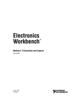
7. Controller functions
7.1 Remote controller YR-H49(used for
AP182ACBEA, AS182AVERA)
20
21
B
22
A
19
27
18
28
17
25
24
23
26
16
15
14
TEMP
ON
OFF
11
HEALTH
1
FAN
12
HEALTH
Used to set Health operation function
12 FAN
Used to select fan speed: AUTO, LOW FAN, MED
FAN, HIGH FAN.
13 SWING
Used to set UP/DOWN air sending and RIGHT/LEFT
air sending direction.
TEMP
Used to set temp.,temp. range:16 C~30 C
14
15 Timer ON/OFF display
16 Fan speed and air sending direction display
MODE
2
LOW
SLEEP
SWING
8
CLOCK
SET
3
TIMER
HEAT
RESET
LIGHT
MID
HIGH
AUTO
13
17 Swing direction display
9
18 Room temperature display
4
7
6
11
19 Sleep
29
LOCK
5
10
state display
Health display
Display when set Health operation function.
21 Electric Heating display
20
22
Fresh Air state display
Battery Capacity display
Display when the electric power of the battery is
insufficient.
24 Lock state display
25 Temperature display
Used to display the set temperature and room
temperature.
26 Clock display
27 Humidifying display
28 Power/Soft operation display
29 HEAT
Select Auxiliary electric heater
23
1 Power ON/OFF
Used for unit start and stop.
2 MODE
Used to select AUTO run,COOL, DRY,
HEAT and FAN operation.
3 CLOCK
Used to set correct time.
4 TIMER
Used to select TIMER ON, TIMER
OFF, TIMER ON/OFF.
5 LOCK
Used to lock buttons and LCD display.
6 RESET
Used to reset the controller back to normal
condition.
7 HOUR
Used to set clock and timer setting.
8 SLEEP
Used to select sleep mode
9 SET
Used to confirm Timer and Clock setting.
10 LIGHT
Control the light up and go out of the control
panel's background light source and control
the switch of the buzzer.
Note: All the above functions will be a little different for the specific models.
-33-
Commercial Air Conditioner
Model: AU182AFERA
AD182AMERA, AS182AVERA
Operation instructions
Clock set
MODE
SLEEP
When unit is started for the first time
and after replacing batteries in remote
controller, clock should be adjusted as follows:
Press CLOCK button, "AM"or "PM" flashes.
Press or to set correct time. Each press will increase
or decrease 1 min . If the button is kept pressed, time will change quickly.
After time setting is confirmed, press SET, "AM" and "PM"
stop flashing, while clock starts working.
SWING
SET
CLOCK
1
TIMER
3
2
HEAT
RESET
LIGHT
LOCK
Remote controller's operation
When in use, put the signal transmission head directly to the receiver hole on the indoor unit
The distance between the signal transmission head and the receiver hole should be within 7m without
any obsacles as well.
Don't throw the controller, prevent it from being damaged.
When electronic-started type fluorescent lamp or change-over type fluorescent lamp or wireless telephone
is installed in the room, the receiver is apt to be disturbed in receiving the signal so the distance to the
indoor unit should be shorter.
Loading of the battery
Slightly press " " and push down the cover.
Load the batteries as illustrated.
2 R-03 dry batteries, (cylinder)
Be sure that the loading is in line with the "+"/"-" pole
request as illustrated.
Put on the cover again.
S
TE
NU
MI
Confirmation indicator:
In disorderation, reload the batteries or load the new batteries
after 5 mins.
Note:The waster batteries should be disposed properly,use two
2R-03 dry batteries
new same-type batteries when loading.
If the remote controller cant function normally or doesnt work at
all,use a sharp-pointed item to press the reset key.
Hint:Remove the batteries in case unit wont be in usage for a long period.
If there are any displays after taking-out just need to press reset key.
When throw away the waste batteries, please perform in accordance with the local regulation.
Auto Mode
1
2
Press ON/OFF button
Unit starts running.
The previous status appears on the display
(except. TIMER, SLEEP mode)
TEMP
ON
OFF
HEALTH
4
Press MODE button. For each press,
operation mode changes as follows:
1
FAN
3
MODE
2
SLEEP
SWING
CLOCK
SET
TIMER
HEAT
AUTO COOL
DRY FAN
HEAT
RESET
Select Auto run,
"
" appears and auto run starts.
-34-
LIGHT
LOCK
Commercial Air Conditioner
3
Select temp. button
Press TEMP button
Every time the button is pressed, temp.
setting increases 1 C
Every time the button is pressed, temp.
setting decreases 1 C
If the button is kept pressed, setting will
increase or decrease quickly.
4
Press FAN,For each press, operation mode
changes as follows:
Remote
controller
LOW
MID
HIGH
Model: AU182AFERA
AD182AMERA, AS182AVERA
Note:
During Auto run operation, temp. setting will be
shown in LCD display, unit will select heating,
cooling or fan operation according to the room
temp.
AUTO
Unit runs at the speed displayed on LCD.
When fan speed is AUTO,it is changed automatically
according to the indoor temperature.
Press ON/OFF button
Unit stops running.
5
Cooling Mode
1
Press ON/OFF button
Unit starts running.
The previous status appears on the display
(except. TIMER, SLEEP mode)
2
Press MODE button. For each press,
operation mode changes as follows:
TEMP
3
HEALTH
1
ON
OFF
3
FAN
4
5
MODE
2
SLEEP
SWING
CLOCK
SET
Remote
controller
3
TIMER
HEAT
RESET
LIGHT
LOCK
4
AUTO COOL
DRY FAN
HEAT
Select cooling operation, Shows" "
Cooling operation starts.
Select temp. button
Press TEMP button
Every time the button is pressed, temp.
setting increases 1 C
Every time the button is pressed, temp.
setting decreases 1 C
If the button is kept pressed, setting will
increase or decrease quickly.
Press FAN button. For each press, fan speed
changes as follows:
Remote
controller
LOW
MID
HIGH
AUTO
Unit runs at the speed displayed on LCD.
When fan speed is AUTO,it is changed outomatically
according to the indoor temperature.
5
Press ON/OFF button
Unit stops running,and when entry this mode for the
next time,it will show the previous setting.
-35-
Commercial Air Conditioner
Model: AU182AFERA
AD182AMERA, AS182AVERA
Dry Mode
1
Press ON/OFF button
Unit starts running.
The previous status appears on the display
(except. TIMER, SLEEP mode)
2
Press MODE button. For each press, operation mode changes
as follows:
TEMP
3
HEALTH
1
ON
OFF
3
FAN
Remote
controller
4
5
MODE
2
SLEEP
SWING
CLOCK
SET
HEAT
LIGHT
DRY FAN
Select Drying operation shows"
Dry operation starts
TIMER
RESET
AUTO COOL
HEAT
"
LOCK
3
Select temp. button
Press TEMP button
Every time the button is pressed, temp. setting increases 1 C
Every time the button is pressed, temp. setting decreases 1 C
If the button is kept pressed, setting will increase or decrease
quickly.
4
Press FAN button. For each press, fan speed changes as
follows:
Remote
controller
LOW
MID
HIGH
AUTO
Unit runs at the speed displayed on LCD.
In DRY mode, when room temp.becomes 2 C lower than temp. setting,unit will run intermittently at LOW speed
regardless of FAN setting.
Press ON/OFF butto nUnit stops running, and when entering this mode
for the next time, it will show the previous setting
5
COOL operation starts when room
temp. is higher than temp. setting.
Ultra-low air flow
Temp.setting+2 C
Temp.setting
On reaching 2 C lower than temp.
setting,unitwill run in mild DRY mode.
Fan Mode
1
Press ON/OFF button
Unit starts running.The previous status appears on the display
(except. TIMER, SLEEP mode)
2
Press MODE button. For each press,operation mode
changes as follows:
TEMP
HEALTH
1
ON
OFF
3
MODE
2
SLEEP
SWING
CLOCK
SET
TIMER
HEAT
RESET
Remote
controller
FAN
4
LIGHT
AUTO
COOL
Select Fan operation shows "
3
DRY
FAN
HEAT
", Fan operation starts.
Press FAN button. For each press, fan speed changes as
follows:
LOCK
LOW
MID
HIGH
Unit runs at the speed displayed on LCD.
-36-
Commercial Air Conditioner
Model: AU182AFERA
AD182AMERA, AS182AVERA
Press ON/OFF button
Unit stops running, and when entering this mode for the
next time, it will show the previous setting.
4
Note:
In this mode, temp. can't be selected, temp.setting will not be
shown in LCD display.In Fan operation mode, "AUTO" fan
speed is not available. Operation cycles are as follows:
LOW
MID
HIGH
Heating Mode
Note: For cooling only type, this function is invalid.
1
Press ON/OFF button
Unit starts running.
The previous status appears on the display
(except. TIMER, SLEEP mode)
2
Press MODE button. For each press,operation mode
changes as follows:
TEMP
3
HEALTH
1
ON
OFF
3
5
SLEEP
SWING
CLOCK
SET
Select Heating operation "
operation starts.
" appears and Heating
Select temp. button
Press TEMP button
Every time the button is pressed, temp. setting increases 1 C
Every time the button is pressed, temp. setting decreases 1 C
If the button is kept pressed, setting will increase or
decrease quickly.
4
Press FAN button. For each press, fan speed changes as
follows:
HEAT
LIGHT
HEAT
3
TIMER
RESET
DRY FAN
4
MODE
2
AUTO COOL
FAN
LOCK
LOW
MID
HIGH
AUTO
In heat mode,warm air will blow out after a short period of
time due to cold-draft prevention function.
5
Press ON/OFF button
Unit stops running, and when entering this mode for the next
time, it will show the previous setting.
-37-
Commercial Air Conditioner
Model: AU182AFERA
AD182AMERA, AS182AVERA
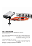
Air flow adjustment
Swing louvers
(Vertical louvers)
(Horizontal louvers)
Up and down
Side from side
Position 1
Position 1
Position 2
Position 2
Position 3
TEMP
ON
OFF
HEALTH
Position 4
SLEEP
SWING
2
1
Position 5
SET
TIMER
Position 6
HEAT
RESET
Position 4
FAN
MODE
CLOCK
Position 3
LIGHT
Position 5
[COOL/DRY/FA
N/AUTO(COOL)
HAVE NOT]
Position 6
(AUTO SWING)
Position 7
LOCK
Position 8
Fixed position
Press the SWING
again to fix the
vertical louvers at your desired position.
Side from side
Swing
Press SWING
the horizontal
louvers move from up to down.
Swing
Press SWING
the vertical
louvers move from side to side.
Fixed position
Press the SWING
again to fix the
horizontal louvers at your desired position.
Note: Put louvers at up position in cooling and down position in heating mode.
This will be helpful to keep an even room temp.
Notice: In cooling or dry operation, don't put horizontal louvers at downward
position for a long time, or outlet grill might get frosted. Don't expose
your skin to cool or warm air for a long time.
SLEEP Mode
Remote control unit
Before go to bed, you can press the Sleep button, the air conditioner will operate in comfortable sleep mode to make
your sleep more comfortable.
-38-
Commercial Air Conditioner
Model: AU182AFERA
AD182AMERA, AS182AVERA
Usage of the Sleep function
The Sleep running starts
After starting, set the Run mode and press the Sleep
button.
The Sleep running stops
About 6 hours
Run mode
1. In cooling and dry
1 hour
After starting of the Sleep operation, the temperature Will
be raised for 1 C higher than the set temperature 1 hour
later,and be raised for 1 C after another hour. It continues
under that condition for 6 hours, then the machine will be
switched off. The temperature is higher than the set
temperature so as to avoid catching cold in sleeping.
Raise 1 C
Raise 1 C
1 hour
Close down
the machine
Set the
temperature
In cooling and dry
2. In heating ( the single-cooling conditioners do not
have the
function)
After the Sleep running starts, the temperature will drop for 2 C after another
one hour. The temperature will raise for 1 C after 3 hours running under
the above temperature, and the conditioner will be closed down after running
for 3 hours. The temperature is lower than the set temperature so as to
avoid uneasiness in sleeping.
TEMP
ON
OFF
HEALTH
Close down
the machine
Set the
temperature
FAN
MODE
SLEEP
1 hour
SWING
SET
CLOCK
Drop for 2 C
1 hour
Drop for 2 C
TIMER
HEAT
Raise 1 C
3 hours
RESET
LIGHT
About 3 hours
LOCK
The Sleep running starts
In heating
The Sleep running stops
3. In automatic running
The conditioner will run under automatically selected working mode of sleeping.
4. In Fan running
The Sleep function is invalid.
Timer on/off operation
Remote control unit
TIMER operation
Set Clock correctly before starting Timer operation (refer to page 2)
You can let unit start or stop automatically at following times: Before you wake up in the morning, or get back from outside or
after you fall asleep at night.
TIMER ON/OFF
(1) After unit start, select your desired operation mode.
Operation mode will be displayed on LCD.
(2) TIMER mode selection
Press TIMER button to change TIMER mode.
Every time the button is pressed, display changes as follows:
Remote
controller
ON
AM 12:00
TIMER ON
OFF
PM 12:00
TIMER OFF
ON
AM 12:00
OFF
PM 12:00
BLANK
TIMER ON-OFF
Select your desired TIMER mide (TIMER ON or TIMEROFF) ON or OFF will flash.
-39-
Commercial Air Conditioner
Model: AU182AFERA
AD182AMERA, AS182AVERA
(3) Timer setting
Press HOUR / button.
Every time the button is pressed, time increases 1 min, If button is kept
pressed, time will change quickly.
Every time the button is pressed, time decreases 1 min, If button is kept
pressed, time will change quickly. Time will be shown on LCD. It can be
adjusted within 24 hours.
(4) Confirming your setting
After setting correct time, press SET button to confirm, " ON "
or " OFF " stops flashing.
Time displayed: Unit starts or stops at x hour x min (TIMER
ON or TIMER OFF)
Timer mode indicator on indoor unit lights up.
TEMP
ON
OFF
HEALTH
FAN
MODE
To cancel TIMER mode
SLEEP
SWING
CLOCK
SET
TIMER
Just press TIMER button several times until TIMER mode disappears.
HEAT
LIGHT
RESET
LOCK
Hints
After replacing batteries or a power failure happens, Time setting should be reset.
Remote controller possesses memory function when use TIMER mode next time, just Press SET button after
mode selecting if timer setting is the same as previous one.
Timer on-off function
Remote controller operation TIMER ON-OFF
(1) After unit start, select your desired operation mode.
Operation mode will be displayed on LCD.
(2) TIMER mode selection
Press TIMER button to change TIMER mode.
Every time the button is pressed, display changes as follows:
Remote
controller
ON
AM 12:00
TIMER ON
OFF
PM 12:00
TIMER OFF
ON
AM 12:00
OFF
PM 12:00
BLANK
TIMER ON-OFF
Select your desired TIMER mide (TIMER ON or TIMEROFF) ON or OFF
will flash.
(3) Timer setting for TIMER ON
Press HOUR button.
Every time the button is pressed, time increases 1 min. If button is
kept pressed, time will change quickly.
Every time the button is pressed, time decreases 1 min. If button
is kept pressed, time will change quickly.
Time will be shown on LCD.
It can be adjusted within 24 hours.
AM refers to morning and PM to afternoon.
(4) Time confirming for TIMER ON
After time setting, press TIMER button to confirm," ON " stops blinking,
while " OFF " starts blinking.
(5) Time setting for TIMER OFF
Follow the same procedure in "Time setting for TIMER ON".
-40-
TEMP
ON
OFF
1
HEALTH
FAN
MODE
SLEEP
SWING
CLOCK
SET
RESET
6
3
TIMER
2
4
5
LIGHT
HEAT
LOCK
Commercial Air Conditioner
Model: AU182AFERA
AD182AMERA, AS182AVERA
(6) Time confirming for TIMER OFF
After time setting, press SET button to confirm, " OFF " stops flashing.
Time displayed: Unit start or stop at x hour x min
To cancel TIMER mode
Just press TIMER button several times until TIMER mode disappears.
According to the Time setting sequence of TIMER ON or TIMER OFF,either ON-OFF or OFF-ON can be
achieved.
Health & Fresh Air operation
Health operation
After turning on the unit and set the desired working mode. Press the Health
button, the LCD will display "
", the unit begins health operation (start the
negative ion generation device). Press the Health button again, the "
"
displayed on the LCD disappears, health operation is cancelled (turn off the
negative ion generation device).
Note: When indoor fan motor does not work, the unit will automatically turn
off negative ion generation device.
TEMP
HEALTH
1
About Health operation
ON
OFF
FAN
MODE
SLEEP
SWING
CLOCK
SET
LIGHT operation:
TIMER
HEAT
RESET
After the start of Health operation, the negative ion generator will generate
large amount of negative ion, which can effectively balance the amount of
positive & negative ion in the air and has the bacteria-killing and accelerating
the dust deposition of the room to make the room air fresh and healthy.
LIGHT
LOCK
The remote receiver of wall mounted unit is with the background lamp,
press LIGHT button, according to the buzzer state, there are four modes
of background lamp as follows:
1. Buzzer works, 5 seconds later, background lamp is off;
2. Buzzer works, background lamp is on constantly;
3. Buzzer does not work, 5 seconds later, background lamp is off;
4. Buzzer works, background lamp is off constantly
The above modes will be changed as repetition.
Auto restart function
Setting method (to be applied for a necessary situation) :
Setting Method: When the remote controller is on (excluding timer mode and fan mode), press the "SLEEP"
button on the remote controller 10 times within 5 seconds, and after the buzzer rings 4 times, the air conditioner
will enter the state of auto restart.
Cancel Method: Press the "SLEEP" button on the remote controller 10 times within 5 seconds, and after
the buzzer rings 2 timer, the auto restart mode will be cancelled.
Notes: When a power failure suddenly occurs during the air conditioner is working after the power failure
compensation is set, if the air conditioner will not be used for a long time, please cut off the power supply to
prevent its operation from being resumed after the power is supplied again, or press
the "Switch On/Off" button after the power comes again.
After the power failure compensation is set, if power failure suddenly occurs while the air conditioner is working,
it will resume the previous working state when the power is supplied again.
If the unit has not the "SLEEP" button or function, please realize the function by pressing "SWING" with
the same method.
-41-
Commercial Air Conditioner
Model: AU182AFERA
AD182AMERA, AS182AVERA
7.2 Wired controller YR-E12
;=34
50<
0BA=
0BA=
50< =<:F
7867
24<A?0:
=>4?0A8=<
2==:
;43
>?4-740A
3?F
740A
A4@
:=D
345?=@A
58:A4?
58E
740:A7
27429
@D8<6
B<8A <=.
34;0<3
;0<B0:
24<.033.
@[email protected].
A8;4?
2:=29 B>
@D8<6
50<
*
+
A4;>
740:A7
2:=29
?==; A4;>.
@4A A4;>.
A8;4?
@4A
?42=C4?F
27429
58:A4?
?4@4A
3=D< C4<A8:0A8=<
=<
0BA=
=55
?42=C4?F
308:F
;=34
@A0<31F
<=?;0:
=</=55
Buttons function:
MODE:used for select indoor operation mode.
FAN:used for select indoor air flow.
SWING:used for setting indoor swing mode.
HEALTH:used for setting indoor health function.
TEMP + -:used for changing set temperature.
CLOCK:used to adjust time.
+、-:stands for time plus/minus, used to adjust time.
TIMER:used to set timer mode.
RECOVERY:used to switch over air-exchanging mode.
CHECK:auto-diagnostic button.
FILTER:filter-cleaned button.
RESET:reset correct mode button.
Display description:
[MODE] [AUTO]:auto operation mode
[MODE] [FAN ONLY]:air-throwing mode
[MODE] [COOL]:Cooling operation mode
[MODE] [DRY]:Dehumidification mode
[MODE] [HEAT]:Heating operation mode
[MODE] [HEAT] [TES]:In heating mode, auxiliary electric heater is running. Only when the
unit with auxiliary electric heater is in auxiliary electric heating mode, it will display.
[FAN] [AUTO]:auto fan running
-42-
Commercial Air Conditioner
Model: AU182AFERA
AD182AMERA, AS182AVERA
[FAN] [HIGH]:high fan speed
[FAN] [MED]: medium fan speed
[FAN] [LOW]: low fan speed
[FAN] [FIX]: fixed fan speed, it will display only when fixed fan speed is requested to main
indoor unit.
[CENTRAL]:
central control mode
[OPERATION] :running mode
[STAND BY] : waiting mode
[PRE-HEAT] : pre-heating mode
[DEFROST]: defrosting mode
[FILTER] : request of filter to be cleaned
[HEALTH]:health function
[UNIT NO.]
[CEN.ADD]:central control address, the address number will display on “88”
[SYS.ADD.]:system address, the address number will display on “88”
[CHECK]:auto-diagnostic, trouble shooting
[DEMAND]:compulsory operation function, when it works, [CENTRAL] will flash
[SWING]:swing mode
[ROOM TEMP.]:indoor ambient temperature
[SET TEMP.]:set admired temperature
[TIMER][ON] :timer function is on, it will switch over in the sequence below:
[ON][OFF] → [ON][OFF][DAILY] →[ ]
[TIMER][OFF] :timer function is off
[TIMER][ON][OFF] :timer function ON-OFF
[TIMER][ON][OFF][DAILY]:timer ON-OFF will switch over in turn daily
[CLOCK]:clock display, the displaying time is the current time of the clock.
[UP]、[DOWN]:indicator of filter elevating
[VENTILATION][AUTO]:auto ventilation mode
[VENTILATION][RECOVERY]:fully heat exchanging ventilation mode
[VENTILATION][NORMAL]:normal ventilation mode
FAN ONLY OPERATION:
1)Start up operation: press the button of ON/OFF, the system will start up, and will display
[MODE][AUTO];[FAN][AUTO];[ROOM TEMP.]+“24℃”;[CLOCK]+”12:00”.
2) Select MODE: press the MODE button, then you will see in the display section [MODE]
switch over in below sequence:[FAN ONLY]→[COOL]→[DRY]→[HEAT]→[AUTO]→
[FAN ONLY]. Select [FAN ONLY].
3)Select fan speed: press FAN button, then you see in the display section [FAN] switch over
in below sequence: [HIGH]→[MED]→[LOW]→[HIGH]. Select proper fan speed.
4)Power off: press ON/OFF button, indoor unit will be powered off, there are only time and
the ambient temperature in the screen.
-43-
Commercial Air Conditioner
Model: AU182AFERA
AD182AMERA, AS182AVERA
AUTO operation, COOLING, HEATING and DEHUMIDIFICATION operation
1) Start up operation: press the button of ON/OFF, the system will start up, and will display
[MODE][AUTO];[FAN][AUTO];[ROOM TEMP.]+“24℃”;[CLOCK]+”12:00”.
2) Select MODE: press the MODE button, then you will see in the display section [MODE]
switch over in below sequence:[FAN ONLY]→[COOL]→[DRY]→[HEAT]→[AUTO]→[FAN
ONLY]. Select [FAN ONLY].
3) Change set temperature: press TEMP + or – every time, [SET] will display, and set
temperature will increase/reduce 1℃(F).
4) Select fan speed: press FAN button, then you see in the display section [FAN] switch over
in below sequence: [AUTO]→[HIGH]→[MED]→[LOW]→[AUTO]. Select proper fan speed.
5) Select [SWING]: press [SWING] button, swing function is valid. Press again, swing
function is invalid.
6) Set [HEALTH]: used to set the indoor health function. Press it once, [HEALTH] will display
in the display section, then indoor health function is valid. Press it again, [HEALTH] will
disappear, then the health function is invalid.
This function is valid only for the unit with health function.
7) Power off: press ON/OFF button, indoor unit is powered off. There are only time and the
ambient temperature in the screen.
Set TIMER operation:
Adjust clock: when powered on, for the first time to set timer function, the clock will be
adjusted.
Press “CLOCK” button, and set the current clock. Now, “CLOCK” will flash at the frequency
of 2Hz. Press the clock +/- button; the current clock can be adjusted. Until the proper time
comes, press [SET].
TIMER ON operation:
Press TIMER button, and keep pressing it, in the display section [TIMER] will switch over in
below sequence: [ON]→[OFF]→[ON][OFF] → [ON][OFF][DAILY] →[ ]. Select [TIMER]
[ON], then [TIMER] [ON] flashes, press the clock +/- button to adjust the time of TIMER ON,
press [SET] button.
TIMER OFF operation:
Press TIMER button, and keep pressing it, in the display section [TIMER] will switch over in
below sequence: [ON]→[OFF]→[ON][OFF] → [ON][OFF][DAILY] →[ ]. Select [TIMER]
[OFF], then [TIMER] [OFF] flashes, press the clock +/- button to adjust the time of TIMER
OFF, press [SET] button.
TIMER ON-OFF operation:
Press TIMER button, and keep pressing it, in the display section [TIMER] will switch over in
below sequence: [ON]→[OFF]→[ON][OFF] → [ON][OFF][DAILY] →[ ]. Select [TIMER]
[ON] [OFF]. Firstly, [TIMER][ON] flashes, press the clock +/- button to adjust the time of
-44-
Commercial Air Conditioner
Model: AU182AFERA
AD182AMERA, AS182AVERA
TIMER ON, press [TIMER]. [TIMER][ON] will be constant on. Then [TIMER] [OFF] flashes,
press the clock +/- button to adjust the time of TIMER OFF, press [SET]. The time sequence
of timer on and timer off will determine the mode is [TIMER] [ON] →[OFF] or [TIMER] [OFF]
→[ON]. If you want the current time, press [CLOCK] once, current time will display; press
again, [CLOCK] will flash, and press [+][-] to adjust the time.
Note: 1. If the two times are same, the timer state which is set later will flash, in this case,
timer can not be set.
2. When entering TIMER setting state, if you do not input any button in continuous 10
seconds, the unit will quit from the TIMER mode.
Cancel TIMER operation:
In the timer operation state, press [TIMER] button, the unit will quit from the current timer
operation state, and the set data will be memorized, then enter the next timer mode.
[FILTER] function
When the wired controller receives the filter-cleaned signal from indoor unit, [FILTER] will
display. After finishing clean, press [FILTER], the sign [FILTER] disappears, and the
controller will send the filter reset signal to indoor unit.
When the sign [FILTER] not display, it is invalid to press [FILTER] in short time.
FILTER ELEVATING function: (only for the unit with elevating function)
When the filter needs to be cleaned, the panel can be lowered to the admired height by the
[FILTER][UP][DOWN] function. Method is below: In power off state, press [HEALTH] for 10
seconds to enter filter elevating set state. In this state, the sign [FILTER] will flash and [UP]
[DOWN] will display simultaneously, Press TEMP [+], in timer section [UP] will display, while
press TEMP [-], in timer section [DOWN] will display. When it arrives the appropriate position,
press [UP], [UP][DOWN] will display simultaneously, filter will stop going down. Press [UP]
again, filter will go up. Press [FILTER] button to quit the mode.
DEMAND operation function:
By this function, all the indoor units can be made in nominal mode. Set the operation mode
in cooling and then shut off the unit. In the stop state, press [ON/OFF] button for 5 seconds
to enter cooling trial operation state. If it is in heating mode before shut off the unit, then
press [ON/OFF] button for 5 minutes, it will enter heating trial operation state.
In cooling, there will be “LL” in the position where the set temperature displays. In heating,
there will be “HH” in the position where the set temperature displays. The wired controller
will send the [DEMAND] signal to indoor unit. In the [DEMAND] operation, “COOL” or
“HEAT” will display at 1Hz frequency. Indoor fan motor will be fixed at “AUTO” mode. The
indoor units in the same group will quit the [DEMAND] in turn.
At this time, only the buttons of [ON/OFF] and temperature [+] [-] are valid. Press [ON/OFF]
to quit [DEMAND] mode.
-45-
Commercial Air Conditioner
Model: AU182AFERA
AD182AMERA, AS182AVERA
CENTRAL control function
When the central controller selects [CENTRAL] mode, the buttons in the wired controller
except for [CHECK] will be invalid.
VENTILATION mode (only for the unit with fresh air function or heat recovery
function)
Press [RECOVERY] button, then the unit will switch over the ventilation mode:
[
]
→
[VENTILATION][AUTO]
→
[VENTILATION][RECOVERY]
→
[VENTALATION][NORMAL] →[ ], please select appropriate ventilation mode.
Query indoor malfunction history:
In the state of power on or power off, press [CHECK] button, enter the malfunction-querying
mode of all indoor units in the group. Then [CHECK] and [UNIT NO.] will display, and the
actual indoor numbers will be displayed in some sequence (unit number is in decimals). At
the same time, in the time region, there will be the current malfunction and the latest time
malfunction, the displaying format is [XX:YY], in which XX stands for the current malfunction,
if normal, it will display “――”; YY stands for the latest time malfunction. The failure code of
every unit will display for 3 seconds. After the failure codes of all indoor units in the whole
group are displayed, the mode will quit automatically.
Clear abnormal state and malfunction history:
In normal state, press [CHECK] button for 5 seconds to clear abnormal states, at the same
time, wired controller will send the data of “clear abnormal state”, but the malfunction history
still retains.
In normal state, press [CHECK] button for 15 seconds, except for malfunction states, the
malfunction history in wired controller will be cleared.
Query indoor performance state:
In normal state, press both buttons of [CHECK] and [FILTER] for 5 seconds, in the set
temperature region in the screen, [XX] will display, XX is indoor number, which can be
selected by pressing [TEMP] [+] [-]. In the timer region in the screen, [YZZZ] will display, in
which Y stands for data type, ZZZ stands for the corresponding data. which can be selected
by pressing [CLOCK] [+] [-].
Y
A
ZZZ
Indoor capacity (W)
B
C
Request of indoor capacity(Hz)
Temperature of indoor ambient
temp. sensor TA
Temperature of indoor gas pipe
sensor TC1
Temperature of indoor liquid pipe
sensor TC2
Open degree of indoor PMV
d
E
F
-46-
Type
Nominal cooling
capacity/10, decimal
Actual value, decimal
Actual value, decimal
Actual value, decimal
Actual value, decimal
Actual value, decimal
Commercial Air Conditioner
g
H
Preset
Outdoor total capacity
Model: AU182AFERA
AD182AMERA, AS182AVERA
―――
Actual value, decimal
In check mode, press [CHECK] to quit the check mode, and go into normal running
mode.
How to change the function switches?
No.
Type
State of
switch
Changeover of Wired Connected
J01
controller
controller
J02
J06
J07
J03
SW01
①
SW01
②
D1
D2
and
central
Changeover of type of
wired controller
Selection of room temp.
sensor
Auto restart after power
failure
Display
of
temperature
room
Function description
Central controller
Cut off
Wired controller
Connected
Set as simple controller
Cut off
Set as standard controller
Connected
Use the sensor in the wired
controller
Cut off
Use the sensor in the indoor unit
Connected
Common control
Cut off
Auto restart after power failure
Connected
Yes
Cut off
No
Changeover of master or
slave controller
ON
Set as slave controller
OFF
Set as master controller
℃ or ℉
ON
℉
OFF
℃
Connected
Indoor unit in shorted time
function
Cut off
Common control
Connected
Send compulsorily defrost signal
to indoor unit
Cut off
Common control
Shorten time function
Compulsorily defrost
Note: 1. The switches in grey can be operated after opening the cover of wired controller.
2. Switches or jumper wire must be adjusted when the wired controller is powered off. If the
wired controller is powered on, the above operations will be invalid.
3. Shorten time function
In normal operation, D1 is in short circuit, it will enter shorten time mode, and the time will be
shortened in the proportion of 60:1. In shorten time mode, LED will flash at the frequency of
0.5 second. Cut off D1, it will quit the shorten time mode and return to the normal operation
mode.
4. Compulsorily defrost
In heating mode 30℃ and in High fan speed, D2 is in short circuit, it will enter compulsorily
defrost mode; cut off D2, it will quit. It is always be used when in testing to see if the defrost
function is good.
5. Lock function
-47-
Commercial Air Conditioner
Model: AU182AFERA
AD182AMERA, AS182AVERA
There is no lock function only in the wired controller. But when it is connected with a central
controller, if the central controller is set to “central”, the buttons in the wired controller will be
invalid, or the buttons will be valid.
Failure code (for the unit with wired controller YR-E12):
For
remote
type,
flash
times
Failure
code on
wired
controller
For
central
control,
failure
code
10
08
21D
Drainage
abnormal
system
Float switch broken down
for
more
than
25m
continuously
○
1
01
01D
Indoor ambient temp.
sensor failure
sensor broken down or
short circuit for more than
2m continuously
○
2
02
02D
Indoor coil
sensor failure
temp.
sensor broken down or
short circuit for more than
2m continuously
○
3
4A
11D
Outdoor
ambient
temp. sensor failure
sensor broken down or
short circuit for more than
2m continuously
○
4
49
12D
Outdoor coil temp.
sensor
failure
(compressor
discharging
temp.
sensor)
Sensor broken down or
short circuit for more than
2m continuously
○
5
48
10D
Over-current
protection
CT check abnormal 3 times
in 30m
※
6
53
14D
High
abnormal
pressure
High pressure switch acts 3
times in 30m
※
7
47
22D
Power
abnormal
supply
Fault phase, short of
phase, out of balance
greatly
※
8
07
06D
Communication
between
wired
controller and indoor
abnormal
Communication abnormal
for
more
than
4m
continuously
○
9
06
05D
Communication
between indoor and
outdoor abnormal
Communication abnormal
for
more
than
4m
continuously
○
11
0B
30D
Outside alarm signal
input
Outside
signal
broken
down for more than 10s
○
12
03
20D
Gas
Sensor broken down or
○
Failure description
pipe
temp.
-48-
Reason
Remarks
sensor abnormal
short circuit for more than
2m continuously
Solenoid
valve
incorrectly
3
continuously
13
0D
31D
Solenoid
abnormal
14
4C
15D
15
05
16
valve
act
times
○
Discharging
temp.
sensor abnormal
Sensor broken down or
short circuit for more than
2m continuously
○
17D
EEPROM abnormal
EEPROM data missing
Run as the
default
value
54
26D
Pressure
abnormal(low
pressure)
Low pressure switch acts in
normal running
○
17
50
15D
Compressor overheat
the
discharging
temperature is higher than
120degree
Resumable
if
lower
than
100degree
18
0C
23D
Abnormal mode
Indoor operation mode is
different with the running
indoor unit.
○
19
4B
18D
Outdoor
coil
B(suction
temp
sensor—for MRV II)
Sensor broken down or
short circuit for more than
2m continuously
○
20
4D
15D
Outdoor discharging
B(oil
temp
sensor—for MRV II)
Sensor broken down or
short circuit for more than
2m continuously
○
21
32
07D
Power module failure
Power module overheat, or
over current, or short circuit
※
22
54
08D
Outdoor DC fan motor
failure
※
○ shows resumable fault, ※ shows it is not resumable fault.
Setting address method:
The address setting can be realized by setting indoor PCB.
If you use the group control function, there should be a master unit and 15 sets of slave units.
For the master unit, the SW5-3 should be at “ON”. For the slave units, the SW5-3 should be
at “OFF”.
Please refer the below table,
Indoor
unit
SW1-4
SW1-3
SW1-2
SW1-1
address
1
OFF
OFF
OFF
OFF
2
OFF
OFF
OFF
ON
-49-
Commercial Air Conditioner
3
4
5
6
7
8
9
10
11
12
13
14
15
16
OFF
OFF
OFF
OFF
OFF
OFF
ON
ON
ON
ON
ON
ON
ON
ON
OFF
OFF
ON
ON
ON
ON
OFF
OFF
OFF
OFF
ON
ON
ON
ON
ON
ON
OFF
OFF
ON
ON
OFF
OFF
ON
ON
OFF
OFF
ON
ON
Model: AU182AFERA
AD182AMERA, AS182AVERA
OFF
ON
OFF
ON
OFF
ON
OFF
ON
OFF
ON
OFF
ON
OFF
ON
If you use central control type, SW1, SW2 will be used simultaneously.
Wiring request in central control type: port A-B is connected with indoor
through 2-core shield wire. Requirements:
1. Port A connects with port CN16(A)of all indoor units.
2. Port B connects with port CN16(B)of all indoor units.
Address on Indoor unit SW2-3 SW2-2 SW2-1 SW1-4 SW1-3
central
address
controller
1
1
OFF
OFF
OFF
OFF
OFF
2
2
OFF
OFF
OFF
OFF
OFF
3
3
OFF
OFF
OFF
OFF
OFF
4
4
OFF
OFF
OFF
OFF
OFF
5
5
OFF
OFF
OFF
OFF
ON
6
6
OFF
OFF
OFF
OFF
ON
7
7
OFF
OFF
OFF
OFF
ON
8
8
OFF
OFF
OFF
OFF
ON
9
9
OFF
OFF
OFF
ON
OFF
10
10
OFF
OFF
OFF
ON
OFF
11
11
OFF
OFF
OFF
ON
OFF
12
12
OFF
OFF
OFF
ON
OFF
13
13
OFF
OFF
OFF
ON
ON
14
14
OFF
OFF
OFF
ON
ON
15
15
OFF
OFF
OFF
ON
ON
16
16
OFF
OFF
OFF
ON
ON
17
17
OFF
OFF
ON
OFF
OFF
18
18
OFF
OFF
ON
OFF
OFF
19
19
OFF
OFF
ON
OFF
OFF
20
20
OFF
OFF
ON
OFF
OFF
-50-
port CN16(A-B)
SW1-2 SW1-1
OFF
OFF
ON
ON
OFF
OFF
ON
ON
OFF
OFF
ON
ON
OFF
OFF
ON
ON
OFF
OFF
ON
ON
OFF
ON
OFF
ON
OFF
ON
OFF
ON
OFF
ON
OFF
ON
OFF
ON
OFF
ON
OFF
ON
OFF
ON
Commercial Air Conditioner
21
22
23
24
25
26
27
28
29
30
31
32
33
34
35
36
37
38
39
40
41
42
43
44
45
46
47
48
49
50
51
52
53
54
55
56
57
58
59
60
61
62
63
21
22
23
24
25
26
27
28
29
30
31
32
33
34
35
36
37
38
39
40
41
42
43
44
45
46
47
48
49
50
51
52
53
54
55
56
57
58
59
60
61
62
63
OFF
OFF
OFF
OFF
OFF
OFF
OFF
OFF
OFF
OFF
OFF
OFF
OFF
OFF
OFF
OFF
OFF
OFF
OFF
OFF
OFF
OFF
OFF
OFF
OFF
OFF
OFF
OFF
OFF
OFF
OFF
OFF
OFF
OFF
OFF
OFF
OFF
OFF
OFF
OFF
OFF
OFF
OFF
OFF
OFF
OFF
OFF
OFF
OFF
OFF
OFF
OFF
OFF
OFF
OFF
ON
ON
ON
ON
ON
ON
ON
ON
ON
ON
ON
ON
ON
ON
ON
ON
ON
ON
ON
ON
ON
ON
ON
ON
ON
ON
ON
ON
ON
ON
ON
ON
ON
ON
ON
ON
ON
ON
ON
ON
ON
ON
ON
OFF
OFF
OFF
OFF
OFF
OFF
OFF
OFF
OFF
OFF
OFF
OFF
OFF
OFF
OFF
OFF
ON
ON
ON
ON
ON
ON
ON
ON
ON
ON
ON
ON
ON
ON
ON
-51-
Model: AU182AFERA
AD182AMERA, AS182AVERA
OFF
OFF
OFF
OFF
ON
ON
ON
ON
ON
ON
ON
ON
OFF
OFF
OFF
OFF
OFF
OFF
OFF
OFF
ON
ON
ON
ON
ON
ON
ON
ON
OFF
OFF
OFF
OFF
OFF
OFF
OFF
OFF
ON
ON
ON
ON
ON
ON
ON
ON
ON
ON
ON
OFF
OFF
OFF
OFF
ON
ON
ON
ON
OFF
OFF
OFF
OFF
ON
ON
ON
ON
OFF
OFF
OFF
OFF
ON
ON
ON
ON
OFF
OFF
OFF
OFF
ON
ON
ON
ON
OFF
OFF
OFF
OFF
ON
ON
ON
OFF
OFF
ON
ON
OFF
OFF
ON
ON
OFF
OFF
ON
ON
OFF
OFF
ON
ON
OFF
OFF
ON
ON
OFF
OFF
ON
ON
OFF
OFF
ON
ON
OFF
OFF
ON
ON
OFF
OFF
ON
ON
OFF
OFF
ON
ON
OFF
OFF
ON
OFF
ON
OFF
ON
OFF
ON
OFF
ON
OFF
ON
OFF
ON
OFF
ON
OFF
ON
OFF
ON
OFF
ON
OFF
ON
OFF
ON
OFF
ON
OFF
ON
OFF
ON
OFF
ON
OFF
ON
OFF
ON
OFF
ON
OFF
ON
OFF
ON
OFF
Commercial Air Conditioner
64
65
66
67
68
69
70
71
72
73
74
75
76
77
78
79
80
81
82
83
84
85
86
87
88
89
90
91
92
93
94
95
96
97
98
99
100
101
102
103
104
105
106
64
65
66
67
68
69
70
71
72
73
74
75
76
77
78
79
80
81
82
83
84
85
86
87
88
89
90
91
92
93
94
95
96
97
98
99
100
101
102
103
104
105
106
OFF
ON
ON
ON
ON
ON
ON
ON
ON
ON
ON
ON
ON
ON
ON
ON
ON
ON
ON
ON
ON
ON
ON
ON
ON
ON
ON
ON
ON
ON
ON
ON
ON
ON
ON
ON
ON
ON
ON
ON
ON
ON
ON
ON
OFF
OFF
OFF
OFF
OFF
OFF
OFF
OFF
OFF
OFF
OFF
OFF
OFF
OFF
OFF
OFF
OFF
OFF
OFF
OFF
OFF
OFF
OFF
OFF
OFF
OFF
OFF
OFF
OFF
OFF
OFF
OFF
ON
ON
ON
ON
ON
ON
ON
ON
ON
ON
ON
OFF
OFF
OFF
OFF
OFF
OFF
OFF
OFF
OFF
OFF
OFF
OFF
OFF
OFF
OFF
OFF
ON
ON
ON
ON
ON
ON
ON
ON
ON
ON
ON
ON
ON
ON
ON
ON
OFF
OFF
OFF
OFF
OFF
OFF
OFF
OFF
OFF
OFF
-52-
Model: AU182AFERA
AD182AMERA, AS182AVERA
ON
OFF
OFF
OFF
OFF
OFF
OFF
OFF
OFF
ON
ON
ON
ON
ON
ON
ON
ON
OFF
OFF
OFF
OFF
OFF
OFF
OFF
OFF
ON
ON
ON
ON
ON
ON
ON
ON
OFF
OFF
OFF
OFF
OFF
OFF
OFF
OFF
ON
ON
ON
OFF
OFF
OFF
OFF
ON
ON
ON
ON
OFF
OFF
OFF
OFF
ON
ON
ON
ON
OFF
OFF
OFF
OFF
ON
ON
ON
ON
OFF
OFF
OFF
OFF
ON
ON
ON
ON
OFF
OFF
OFF
OFF
ON
ON
ON
ON
OFF
OFF
ON
OFF
OFF
ON
ON
OFF
OFF
ON
ON
OFF
OFF
ON
ON
OFF
OFF
ON
ON
OFF
OFF
ON
ON
OFF
OFF
ON
ON
OFF
OFF
ON
ON
OFF
OFF
ON
ON
OFF
OFF
ON
ON
OFF
OFF
ON
ON
OFF
OFF
ON
OFF
ON
OFF
ON
OFF
ON
OFF
ON
OFF
ON
OFF
ON
OFF
ON
OFF
ON
OFF
ON
OFF
ON
OFF
ON
OFF
ON
OFF
ON
OFF
ON
OFF
ON
OFF
ON
OFF
ON
OFF
ON
OFF
ON
OFF
ON
OFF
ON
Commercial Air Conditioner
107
108
109
110
111
112
113
114
115
116
117
118
119
120
121
122
123
124
125
126
127
128
107
108
109
110
111
112
113
114
115
116
117
118
119
120
121
122
123
124
125
126
127
128
ON
ON
ON
ON
ON
ON
ON
ON
ON
ON
ON
ON
ON
ON
ON
ON
ON
ON
ON
ON
ON
ON
ON
ON
ON
ON
ON
ON
ON
ON
ON
ON
ON
ON
ON
ON
ON
ON
ON
ON
ON
ON
ON
ON
OFF
OFF
OFF
OFF
OFF
OFF
ON
ON
ON
ON
ON
ON
ON
ON
ON
ON
ON
ON
ON
ON
ON
ON
-53-
Model: AU182AFERA
AD182AMERA, AS182AVERA
ON
ON
ON
ON
ON
ON
OFF
OFF
OFF
OFF
OFF
OFF
OFF
OFF
ON
ON
ON
ON
ON
ON
ON
ON
OFF
OFF
ON
ON
ON
ON
OFF
OFF
OFF
OFF
ON
ON
ON
ON
OFF
OFF
OFF
OFF
ON
ON
ON
ON
ON
ON
OFF
OFF
ON
ON
OFF
OFF
ON
ON
OFF
OFF
ON
ON
OFF
OFF
ON
ON
OFF
OFF
ON
ON
OFF
ON
OFF
ON
OFF
ON
OFF
ON
OFF
ON
OFF
ON
OFF
ON
OFF
ON
OFF
ON
OFF
ON
OFF
ON
Commercial Air Conditioner
Model: AU182AFERA
AD182AMERA, AS182AVERA
Electrical functions of wired controller:
1.Function difference between master wired controller and slave one:
Contrastive items
Function
Master wired controller
All of functions
Slave wired controller
Only
with
below
functions:
ON/OFF, MODE, FAN SPEED,
SET TEMP., SWING
2. Function difference between simple wired controller and the standard one:
Contrastive item
Function
Standard wired controller
With all functions
Simple wired controller
Only can control ON/OFF, MODE,
FAN, TEMP.,SWING.
Can be either of Master Only can be Master controller
and Slave controller
Master/Slave
selection
3. Wiring connections of wired controller:
A
indoor 1
indoor 2
indoor N
indoor 15
indoor 16
(master unit)
wired controller
wired controller
wired controller
wired controller
wired controller
C
B
A
control wiring of wired controller, polar.
wired controller
B
C
indoor 1
3
2
1
wired controller
3
2
1
wired controller
indoor 1
polar wire
polar wire
polar wire
C
B
A
C
B
A
C
B
A
wired controller
wired controller
wired controller
There are three methods to connection wired controller and the indoor units:
A. One wired controller can control max. up to 16 sets of indoor units, and 3
pieces of polar wire must connect the wired controller and the master unit (the
indoor unit connected with wired controller directly), the others connect with
the master unit through 2 pieces of polar wire.
B. One wired controller controls one indoor unit, and the indoor unit connects
with the wired controller through 3 pieces of polar wire.
C. Two wired controllers control one indoor unit. The wired controller
-54-
Commercial Air Conditioner
Model: AU182AFERA
AD182AMERA, AS182AVERA
connected with indoor unit is called master one, the other is called slave one.
Master wired controller and indoor unit; master and slave wired controllers are
all connected through 3 pieces of polar wire.
3. Communication wiring:
The wired controller is equipped with special communication wiring in the
accessories. 3-core terminal (1-white 2-yellow 3-red) is connected with the
terminal
A、B、C of wired controller respectively.
The communication wiring is 4 meter long; if the actual length is more than it,
please distribute wiring according to below table:
Communication wiring length(m)
<100
≥100 and <200
≥200 and <300
≥300 and <400
≥400 and <600
Dimensions of wiring
0.3mm2X3-core shielded wire
0.5mm2X3-core shielded wire
0.75mm2X3-core shielded wire
1.25mm2X3-core shielded wire
2mm2X3-core shielded wire
※ One side of the shielded sheet of communication wire must be earthed.
-55-
Commercial Air Conditioner
Model: AU182AFERA
AD182AMERA, AS182AVERA
8. Electrical Control Functions
8.1. Outdoor electric control functions
8.1.1 Outdoor running frequency and the control procedure
8.1.1.1 Compressor startup
Every time compressor is from OFF to ON, no matter how is the indoor target frequency, compressor
running frequency must be stay at 40Hz and 60Hz for 1 minutes (At outdoor discharging temp.
overhigh protection and compressor overcurrent protection, the frequency will be reduced), and then
rise up to the target frequency. After the unit is in normal, the above procedure is not available.
Note: If the startup frequency for the first time is over 40Hz or 60Hz, it will stay at 40Hz and 60Hz for
1 minute. If the frequency is not over 60Hz, it will only stay at 40Hz for 1 minute. The other conditions
will not be limited.
8.1.1.2 Heating mode, cooling mode and dehumidification
After performing the compressor startup procedure, the unit will run according to the indoor
frequency.
2 minutes later, the unit will compensate the running frequency due to the relative condition.
8.1.1.3 Compressor frequency rising/reducing speed
Rapid rising/reducing frequency speed 1----1Hz/second
Slow rising/reducing frequency speed 1----1Hz/10 seconds
8.1.2 Outdoo motor control
Note: When the outdoor motor needs to change the class, there will be 20-second interval to avoid
the fan speed changing frequently.
8.1.2.1 Fan motor speed class has 7 steps, the rotation and class is as follow:
Class-0
Class-1
Class-2
Class-3
Class-4
Class-5
Class-6
Class-7
stop
500
550
630
680
720
820
860
8.1.2.2 Blowing remain heat after compressor shuts off
In cooling mode, when compressor shuts off, outdoor motor will enter speed Class-5 automatically,
and will shut off after blowing remaining heat for 30 seconds.
8.1.2.3 Outdoor motor control in cooling/dry mode
Speed range: class 1-7
Fan motor locked rotor: When fan motor is requested to work, if fan speed is measured to be
below 50RPM and keep for 15 seconds, the compressor will stop, but 3 minutes later, it will
re-start up again. If within 20 minutes, the condition occurs 3 times, the unit will stop and alarm.
When compressor starts up, the unit will adjust automatically in 3 minutes according to the
outdoor air inlet temperature, and 3 minutes later, the unit will adjust according to the outdoor
ambient temperature and compressor running frequency.
Fan speed chart in 3 minutes after compressor starts up:
Ambient
temp.
~10
10~25
25~
Cool, dry
Class-3
Class-5
Class-7
heat
Class-7
Class-5
Class-3
Fan speed chart in 3 minutes after compressor starts up due to the ambient temp. and running
frequency:
Compressor
frequency in cooling
Tao
Over 28℃
F<25Hz
Class-3
25HZ<=45Hz
Class-5
-56-
45<=F
Class-7
Commercial Air Conditioner
Below 28℃
Class-1
Model: AU182AFERA
AD182AMERA, AS182AVERA
Class-3
Class-5
Compressor frequency
in heating
F<25Hz
25Hz≤F<45Hz
45≤F
Over 15℃
Class-2
Class-4
Class-5
Below 15℃
Class-3
Class-5
Class-7
Tao
8.1.2.4 Outdoor fan speed control when selecting AC motor
Selecting AC motor or DC motor depends on EEPROM.
Blowing remaining heat: compressor shuts off, fan motor will run at low speed for 30 seconds
and then stop.
Fan speed chart in 3 minutes after compressor starts up:
Ambient
temp.
~10
10~25
25~
Cool, dry
Low speed
High speed
High speed
heat
High speed
High speed
Low speed
Fan speed chart in 3 minutes after compressor starts up due to the ambient temp. and running
frequency:
Compressor frequency in
cooling
Tao
25Hz<=F<45Hz
45Hz<=F
Over 28℃
Low speed
High speed
High speed
Below 28℃
Low speed
Low speed
High speed
Compressor frequency in
heating
Tao
F<25Hz
F<25Hz
25Hz≤F<45Hz
45Hz≤f
Over 15℃
Low speed
Low speed
High speed
Below 15℃
Low speed
High speed
High speed
8.1.3 4-way valve control
The 4-way valve control in defrosting: refer to the defrosting procedure.
4-way valve control in other modes:
In heating mode, 4-way valve will open in 10 seconds before compressor starts up. When
compressor not startup or in non-heating mode, 4-way valve will close to ensure the compressor
has stopped for at least 2 minutes.
8.1.4 Outdoor defrosting control
A. Enter condition
In heating mode, compressor is running for 10 minutes contineously, or has run for 45 minutes in all
(when defrosting is over or entering the cooling mode, the counter will be cleared), by measuring the
defrosting sensor TE and outdoor ambient temp. sensor TA, if for 2 minutes the below conditions can
be met contineously, system will enter defrosting mode:
TE≤C×TA-α
Herein: C: TA<0℃, C=0.8
TA≥0℃, C=0.6
α=5:
Entering defrost temperature: -15℃≤C×TA-α≤-5℃
-57-
Commercial Air Conditioner
Model: AU182AFERA
AD182AMERA, AS182AVERA
B. Defrost interval time
When the value of C×TA-α is in the range of -15℃≤C×TA-α, two defrosting interval is
45 minutes.
When the value of C×TA-α is in the range of C×TA-α<-15℃, two defrosting interval is
65 minutes.
C. Defrost procedure
At the beginning of defrost, compressor will firstly stop for 1 mintue, outdoor fan
runs, and 50 seconds later, 4-way valve is OFF.
When compressor starts up, outdoor motor stops and compressor frequency will
go up to the target frequency 90Hz.
In defrosting, the compressor current, compressor discharging protections are
valid. If in defrosting, compressor stops because of the protection or the failure, 3
minutes later, it will resume, and if it still in defrosting time, the unit will still defrost.
The compressor will start up due to the principle of startup in defrosting. If
contineously the compressor can not start up for 3 times, the unit will deal with the
malfunction and quit the defrosting. If in defrosting there is failure, the failure time
will not be included in the defrosting time.
In defrosting, only after the compressor min. running time is over 2 minutes, the
system can quit the defrosting.
The defrosting frequency will not limited by the running frequency, after entering defrosting,the
compressor will not stay at 60Hz and directly go to the target frequency 90Hz.
The quit condition will not change.
D. Quit condition
In any of the below conditions can be met, the defrosting mode will turn into heating operation.
(1): Outdoor heat exchanger temperature is over 10℃ for 80 seconds contineously.
(2): Outdoor heat exchanger temperature is over 14℃ for 20 seconds contineously.
(3): Defrost operation for 10 minutes contineously.
E. If the quit condition can be met, the unit will perform:
Compressor stops, and outdoor motor runs. 50 seconds later the 4-way valve is close, then 60
seconds later, compressor will perform as startup procedure.
F. In defrosting period and in 6 minutes after defrosting, the low pressure is shielded.
G. In defrosting, if receiving the shutoff signal sent from indoor unit, outdoor unit will not deal with it
until the defrosting is over.
8.1.5 PTC output control
When outdoor unit is electrified, PTC output is 0, 10 seconds later, it is 1.
After compressor stops for 10 minutes contineously, PTC output is 0.
When getting the compressor-start signal, firstly PTC output is 1, 5 seconds later,
compressor will start up.
8.1.6 Electric heater control
When shutoff, the electric heater will be controlled by the ambient temperature: below 12℃, working;
over 17℃, stop.
When the unit switched on, electric heater will not work.
8.1.7 Time shorting function
If the time shorting port is in short circuit, the unit will perform a 1/60 time shorting control.
-58-
Commercial Air Conditioner
Model: AU182AFERA
AD182AMERA, AS182AVERA
8.2. Additional functions
8.2.1 The interval between compressor stop to startup again is 3 minutes, which can protection
compressor. If being electrified for the first time, compressor will start up only when the valve
opens to the normal operation angle.
8.2.2 TD high temperature protection
As long as the unit is running, the TD discharging overheat protection will work, but the discharging
sensor failure will alarm 4 minutes later after compressor starts up.
Measure sensor value: measure for 100 times (The program performs for one period needs 5 ms,
every time the system will take samples for 8 times, and make an order for them, taking out 2
average values in the middle, and make an average value.).
TD(℃)
Abnormal stop
120
quick reduce FQY(1HZ/s)
112
slow reduce FQY(1HZ/10s)
108
FQY no change
105
rise FQY(1HZ/10s)
98
rise FQY(1HZ/1s)
TD>120℃ and keeps for 20 seconds, discharging temperature over high protection will work, the
unit will stop and alarm(outdoor indicates, not sending to indoor). If TD>98℃, the unit will resume. If
within 30 minutes, the TD overhigh protection occurs 3 times, the unit will stop and alarm (sending to
indoor), it can not resume automatically.
8.2.3 In heating indoor TC high temperature protection
Indoor heat exchanger temperature will check the indoor coil temperature, if it is over 55℃, the unit
will reduce the compressor motor speed to perform the indoor heat exchanger temperature overhigh
protection. If it is below 48℃, the unit will resume to be normal.
TC
P
reduce slowly
Q
remaining
R
rise slowly
55
52
48
P: reduce at the speed of 1Hz/10s
Q: remain the previous value
-59-
Commercial Air Conditioner
Model: AU182AFERA
AD182AMERA, AS182AVERA
R: rise at the speed of 1Hz/10s
8.2.4 Overcurrent protection(realised by power module)
●In the course of compressor startup, if current is over 21A and keeps for 4 seconds, compressor
will stop and the unit alarms. 3 minutes later, compressor will re-start up, if in 10 minutes, it occurs for
3 times, the unit will stop and alarm.
●Overcurrent reducing frequency protection
When currentn is over 13.9A, compressor will reduce frequency at 1HZ/s, and will stop until it is
below 12A, then rise frequency at 1HZ/20s; when current is below 12A, it will resume the target
frequency.
Remarks: Power module frequency limited point: 88℃, if the frequency reduces down to 86℃, but if
it is up to 90℃, the unit will stop and alarm.
8.2.5 Indoor heat exchanger anti-freezed protection
11℃
9℃
8℃
6℃
5℃
When TC〈 5℃, compressor frequency will reduce at 1HZ/10s
When TC begins to rise up, and 6〈=TC〈=8℃, compressor frequency will remain
When 9℃≤TC, the frequency will rise up at 1HZ/10s
When 12℃≤TC, the frequency will rise up at 1HZ/s
8.2.6 Outdoor temperature limitation
Cool: When outdoor temperature is below 15℃, in cooling, compressor frequency will be limited
below 50Hz, and outdoor fan speed is compusorily Class-1.
Heat: When outdoor temperature is over 20℃, in heating, compressor frequency will be limited
below 50Hz, and outdoor fan speed is compulsorily Class-1.
If the above is AC motor, the compulsory fan speed will be low speed.
8.2.7 Rated operation
● Rated cooling:
When receiving the indoor rated operation command, the unit will enter rated cooling operation.
Rated heating:
When receiving the indoor rated operation command, the unit will enter rated cooling operation.
When receiving the indoor min. heating operation command, the unit will enter min. heating
operation.
In rated operation period, the frequency can be adjusted by manual. Once being adjusted by
manual, the unit will not receive the indoor frequency.
8.2.8 Outdoor compulsory operation
Compulsory cooling operation
-60-
Commercial Air Conditioner
Model: AU182AFERA
AD182AMERA, AS182AVERA
Put the first bit of dip switch on the indicator board at ON, the unit will enter compulsory cooling
operation, as follow:
Compressor
Current, discharging
Operation
before
3
minutes
later
startup
protection and failure
the base open angle
compressor is running
Normal
1: fixed base open angle
after
Manual adjustment
treatment
normal
normal
1: angle adjusted by
hand
2: fixed running frequency 60HZ
2: frequency adjusted
3: fixed outdoor motor speed:
by hand
class-7
3: fan speed adjusted
by hand
Compulsory heating operation
Put the second bit of dip switch on the indicator board at ON, the unit will enter compulsory heating
operation, as follow:
Compressor
startup
Current,
Operation
discharging
the base open angle
compressor is running
Normal
1: fixed base open angle
protection
before
3
minutes
later
after
Manual adjustment
and
failure treatment
normal
normal
2: fixed running frequency
50HZ
3: fixed outdoor motor speed:
class-7
1:
angle
adjusted
hand
2: frequency adjusted by
hand
3: fan speed adjusted by
hand
8.2.9 High pressure switch
3 minutes later after compressor starts up, the system will check the pipe pressure. If the pipe
pressure is over high and high pressure switch acts for over 30 seconds, the compressor and
outdoor motor will stop, 3 minutes later, the unit will resume. If in 30 minutes the unit stops for 3
times because of overhigh pressure, the system will alarm, then compressor will not start up again;
when being electrified after being powered off, the protection will be cancelled.
2.10 Low pressure switch
When compressor stops, if low pressure switch acts for 30 seconds contineously, the unti will alarm.
The failure will be sent to indoor unit, it will resume due to the pressure signal.
When compressor starts up, in 3 minutes, low pressure switch will be shielded.
When compressor is running, the unit will check pipe pressure, when pipe pressure is over low and
low pressure switch acts for 30 seconds, compressor and outdoor motor stop, the unit will alarm, and
compressor will not start up; when being electrified after being powered off, the protection will be
cancelled.
In defrosting or in 6 minutes after defrosting is over, low pressure switch will be shielded.
8.2.11 Failure code and troubleshooting
Alarm lamp is off when no failure
Ensure that alarm indicating time is over 2 minutes and 50 seconds.
(1): Resumable alarm, and will be sent to indoor unit.
(2): Resumable alarm, but if in 30 minutes it occurs 3 times, it can be resumed only when being
-61-
by
Commercial Air Conditioner
Model: AU182AFERA
AD182AMERA, AS182AVERA
electrified after being powered off.
Failure
Emission
Outdoor
Failure description
Corresponding outdoor CBD failure
code
code
indicator display
01
01
00001
Power module
IPM protection
02
02
00010
DC fan motor failure
DC fan motor failure
03
no
Communication
Outodor alarms, not sends to indoor.
failure
If no communication in 4 minutes, outdoor
00011
shuts off and alarm, the failure can be
resumable.
04
04
00100
05
06
05
00101
06
Compressor
Discharging temp. over 117℃, it will confirm
discharging
3 times in 30 minutes and then send signal to
temperature too high
indoor.
Over current
AC current overhigh protection or current
transducer broken down.
Outdoor
00110
ambient
temp. sensor failure
Resumable, if sensor is disconnected, alarm
will occur and keeps for 3 minutes, then
resumes due to signal.
07
08
09
10
07
08
09
10
00111
01000
01001
01010
Outdoor coil temp.
Outdoor
defrosting
sensor,
sensor failure
sensor abnormal
High pressure switch
Acts 3 times in 30 minutes
failure
Discharging
temp.
sensor failure
Alarm 4 minutes later after starting up,
discharging temperature abnormal
Power supply over
Pre-set for 50Hz
high/low voltage
11
No
No
Overload in heating
No send signal to indoor
12
No
No
No
No send signal to indoor
13
No
No
No
No send signal to indoor
14
14
01110
discharging
Outdoor
EEPROM
Outdoor EEPROM failure
failure
15
1
01111
Power module failure
Compressor blocked
16
1
10000
Power module failure
Compressor heavy vibration
17
1
10001
Power module failure
Abnormal compressor startup
18
18
10010
Power module failure
Compressor running faulty
19
19
10011
Power module failure
Detecting circuit abnormal
20
1
10100
Power module failure
Compressor broken down
21
No
Compressor suction 10 minutes later after startup, measure TS
10101
temp. too high—for over 40℃ for 5 minutes
the unit with EEV
22
No
10110
Communication failure
Not communicate for 4 minutes contineously,
between outdoor PCB
it will alarm
and the module
23
1
10111
Module malfunction
-62-
Module temp. over high
Commercial Air Conditioner
24
No
24
No
11000
No
Model: AU182AFERA
AD182AMERA, AS182AVERA
Low pressure switch
Low pressure switch acts for 30 seconds
failure
contineously
Temperature
cutoff
protection
1)Indoor pipe temp. is abnormal, outdoor default cooling temp. : 5℃, heating temp.: 40℃. The
above temperatures are normal.
2)In defrosting, and in 3 minutes after defrosting is over, if sensor is abnormal, there will not alarm.
8.2.12 Backup operation
Outdoor TC failure treatment: outdoor LED alarms, but the failure code will not be sent to other place,
the outdoor default TC is as follow: cooling temperature, 5℃; heating temperature, 40℃.
8.2.13 Special functions
1) Power operation
When receiving the Power operation signal from indoor, the unit will operate as the set frequency by
EEPROM. Fan speed will depend on the ambient temperature and the frequency. When the Power
signal is cancelled by indoor, the Power operation will stop.
2) Soft operation
When receiving the Soft operation signal from indoor, the unit will operate as the set frequency by
EEPROM. Fan speed will depend on the ambient temperature and the frequency. When the Soft
signal is cancelled by indoor, the Soft operation will stop.
3) Time shorting operation
When receiving the time shorting signal, the unit will perform the 1/60 time shorting operation.
4) Compulsory cooling operation
When receiving the compulsory cooling signal from indoor unit, the unit will execute the compulsory
cooling operation at the frequency sent from indoor. Only discharging temperature protection and
current protection are valid, all the other protections are invalid.
5) Manual defrosting
When receiving the manual defrosting signal from indoor, the unit will enter the defrosting operation
immediately. The interval between two manual defrosts is at least 3 minutes. If the communication
protoco has not the set, this function is not available.
6) Rated operation
When receiving the rated operation signal from indoor, the unit will operate at the frequency and fan
speed set by EEPROM, meanwhile, all the protections are valid.
8.2.14 Outdoor indicator
Five-indicator combination shows the failure code.
4-bit dip switch: the normal position is OFF.
First bit: ON, compulsory cooling. Normal state is OFF.
Second bit: ON, compulsory heating. Normal state is OFF.
Third bit: ON, backup operation (outdoor ambient temp.). Normal state is OFF.
Fourth bit: ON, DC fan motor (OFF, AC fan motor), it will be adjusted due to the actual fan motor.
-63-
Commercial Air Conditioner
Model: AU182AFERA
AD182AMERA, AS182AVERA
Wall mounted unit electric functions:
1. Temperature adjustment function
1.1 In this function, outdoor running frequency depends on the indoor temperature and the set
temperature.
1.2 In auto mode, indoor fan speed will be changed according to the request of temperature
adjustment.
1.3 In heating operation, indoor fan speed will be controlled according to the coil temperature.
1.4 Defrosting
In heating mode, outdoor transfers the defrosting signal to indoor unit, then indoor unit will enter
defrosting mode until outdoor transfers defrost-cancelling signal, then indoor unit will enter
heating mode. In defrosting, there is no over load protection.
1.5 Air flow limitation
When compressor is running, the air flow of indoor fan motor and the limited frequency are as
follow:
Frequency-limited variable
Limited frequency
Air flow (Med)
FQLIMMD
90Hz
Air flow (Low)
FQLIMLO
52Hz
Healthy mode
FUPHEAL
30Hz
2. Indoor fan motor control
2.1 If air flow is adjusted by hand, the target rotation is (High+Low)/2.
If air flow is adjusted automatically, the target rotation is (Auto High+Auto Low)/2, it will not be
counted if being below 10rpm.
2.2 Heat operation
2.2.1 Hot start up
In heating, anti-cold air control is as the following chart:
Heat exchanger temp.
THHOT3
37.0℃
THHOT2
35.2℃
THHOT1
25.2℃
4minutes
THHOT0
23℃
stop ultra low low
set value
low ultra low stop
According to the heat exchanger temperature, fan motor will be controlled due to the above
chart.
1) When heat exchanger temp. rises up, adjust the fan speed due to the heat exchanger temp.
If heat exchanger temp. is below 35.2℃, fan speed is ultra low (When being electrified for the
first time, enter heating mode or defrosting is over, if heat exchanger temp. is below 25.2℃, fan
motor stops; if higher than 25.2℃ and lower than 35.2℃, fan speed is ultra low);
If heat exchanger temp. is between 35.2℃ and 37℃, fan speed is low;
If heat exchanger temp. is higher than 37℃, fan motor will run at set speed.
2) When heat exchanger temp. reduces, adjust the fan speed due to the heat exchanger temp.
If heat exchanger is below 35.2℃ and over 25.2℃, fan speed is low;
If heat exchanger is below 25.2℃, fan speed is ultra low, and remain the state (When being
-64-
Commercial Air Conditioner
Model: AU182AFERA
AD182AMERA, AS182AVERA
electrified for the first time, enter heating mode or defrosting is over, if heat exchanger temp. is
below 25.2℃ and over 16℃, fan speed is ultra low; if heat exchanger temp. reduces below 23
℃, fan motor speeds.).
3) When heat exchanger temp. rises, fan speed will be ultra low and low state, if 4 minutes
later, heat exchanger temp. can not enter the last period, fan speed will rise up to the last speed.
When up to the set speed, fan speed will stay at this state for 4 minutes and then adjust fan
speed due to the heat exchanger temp.
4) When heat exchanger temp. reduces, if fan speed is low for over 4 minutes, the fan motor
will go back to the set speed.
2.2.2 3-minute protection when compressor stops
1) After compressor stops (thermostat is OFF), if coil temperature is below 25.2℃, indoor motor
stops; if coil temperature is over 25.2℃, fan motor will be in low speed, after the fan time is over
50 seconds, if coil temperature is over 28℃, fan motor will be in low speed; if coil temperature is
below 23℃, indoor motor will stop.
2) If the unit is shutoff by remote controller, indoor motor will stop after running at ultra low
speed for 10 seconds.
2.2.3 Compressor restart up
After hot startup, the fan speed is the state set by remote controller.
When in Auto Fan mode, the air flow depends on the temperature.
2.2.4 In defrosting, after running at low speed for 20 seconds, fan motor stops. After defrosting
is over, if compressor stops, indoor motor will stop too. When compressor re-starts up, air flow
can be set at High, Med, Low according to the heat exchanger temperature.
2.3 Cooling operation
When in Auto Fan mode, the air flow will be confirmed according to the temperature.
2.4 Dry operation
2.4.1 If compressor is OFF, and in 3-minute standby:
1)Compressor stops, fan motor will stop too.
2)If 3-minute protection is over, fan is in ultra low state.
3)After 3-minute standby state, compressor will run.
2.4.2 If compressor is ON:
Fan motor will run at the set speed.
When in auto fan mode, the air flow will be adjusted due to the temperature.
3. Power operation (depend on the remote controller, not available for this model)
1) Power operation will keep for 15 minutes.
2) The unit stops or 15 minutes later, the power operation will stop.
3) If changing the operation modes, the power operation will stop.
4) If at soft mode or TIMER ON function works, the power operation stops.
5) In Auto mode, the Power/Soft function can work. In cooling mode, the unit will run at Cooling
Power/Soft mode. In heating mode, the unit will run at Heating Power/Soft mode. In Fan
mode, there is no Power/Soft function.
3.1 Power heating operation
1) Adjust the set temperature, can modulate the temperature.
2) Air flow is Auto Med speed.
3) In defrosting, outdoor unit will not the communication signal of power operation.
4) After Power operation works for 15 minutes, within 10 minutes, compressor can not be OFF,
excluding the failure condition.
-65-
Commercial Air Conditioner
Model: AU182AFERA
AD182AMERA, AS182AVERA
3.2 Power cooling operation
1) Modulate the set temperature.
2) Air flow is Manual High speed.
3) After compressor is running, in 3 minutes, the unit will not make low load protection.
3.3 Not available for Fan, Dry mode.
4. Soft operation
The indoor unit will send the Soft operation signal to outdoor.
4.1 Soft heating
When compressor is running, air flow is SSLO.
When compressor stops, in 20 seconds, air flow is SSLO, and then turn into ultra low.
4.2 Soft cooling
Air flow is SSLO.
4.3 Not available for Fan, Dry mode.
5. Negative ion function
1) When receiving the command, if fan motor is running, the negative ion generator will work
to realize the negative ion emission function.
2) If fan motor stops, the negative ion generator is OFF.
3) When negative ion generator is OFF, at this time, if you set the negative ion function, when
fan motor begins to runs again, the negative ion generator will be ON automatically.
6. TIMER operation
1) Count the time according to the difference between TIMER CLOCK and the present
CLOCK time.
2) When TIMER function works, the TIMER lamp on the indicator board is ON.
3) TIMER OFF
When TIMER OFF is set, the indication on the panel will not change (background lamp is OFF),
the timer icon will display. When timer clock arrives, the operation will stop.
4) TIMER ON
When TIMER ON is set, the indication on the panel only displays the TIMER icon(background
lamp is OFF), When timer clock arrives, the unit will run at the set state.
5) TIMER ON/OFF
The operation will be performed as the set state.
7. SLEEP operation
Sleep function: energy saving function at night, TIMER lamp will be ON.
7.1 Standard sleep function: in cooling or dry mode, after running at SLEEP mode for 1 hour,
the set temperature will rise 1℃, another 1 hour later, the set temperature will rise another 1℃;
the unit continues running for 6 hours, then the unit will stop.
Ts+2
Ts+1
Ts
7.2 Standard sleep function: in heating mode, after running at SLEEP mode for 1 hour, the set
temperature reduces 2℃, another 1 hour later, the set temperature will reduce 2℃, and another
3 hours later, the set temperature rises 1℃; the unit continues running for 3 hours, then the unit
will stop.
-66-
Commercial Air Conditioner
Model: AU182AFERA
AD182AMERA, AS182AVERA
Ts
Ts-2
Ts-3
Ts-4
7.3 Non-standard SLEEP function: the sleep function can realize 1~8 hours sleep mode when
being combined with the TIMER function.
1) When in Auto mode, the unit will make SLEEP operation due to the setting.
2) After setting SLEEP function, the clock can not be adjusted.
3) If sleep time is no more than 8 hours, when the time arrives, the unit wil shut off.
4) If sleep function is set after setting TIMER OFF function, the unit will execute as the
SLEEP function.
5) If SLEEP function is set, the TIMER function can not be set.
6) If sleep function is set after setting TIMER ON function, the sleep function only can be
set befroe the TIMER ON time arrives.
7) After setting sleep function, press CLOCK button to check the clock; press TEMP
button to display the set temperature, and press again to change the set temperature.
8. Auto operation
Full auto operation
If the unit is at Auto mode, the system will adjust the operation mode according to the
temperature difference between the set temperature and the room temperature. Below Tr
stands for room temperature, Ts stands for room temperature.
If entering Auto mode for the first time, the unit will execute as follow:
Tr≥Ts-3℃
select cooling mode
Tr<Ts-3℃
select heating mode
After entering Auto mode, the operation mode can be changed between cooling and heating: if
the unit is in cooling mode at present, when the compressor arrives the stop temperature, the
compressor stops; after compressor stops for 15 minutes, the unit will check the temperature
again, at this time, if Tr<Ts-3℃, the unit will enter heating mode, or it will still be in cooling
mode; if the unit is in heating mode at present, when the compressor arrives the stop
temperature, compressor will stop, afte compressor stops for 15 minutes, the unit will check the
room temperature, if Tr>Ts+3℃, the unit will enter cooling mode, or it will still be in heating
mode.
In this mode, TIMER mode and SLEEP mode are available. In cooling mode, the unit will be in
COOL SLEEP; in heating, the unit will be in HEAT SLEEP.
Fan blade can swing or be fixed on one position, and fan speed can be set at High, Med, Low or
Auto.
9. Trial running
The frequency is 58Hz, and the unit is in cooling mode, fan speed is High.
After the trial running time is 30 minutes, the unit will shut off.
In trial running, the unit will quit this state if receiving the remote signal.
There is no low load protection.
10. Low load protection
In cooling/dry mode, make the low load protection due to the heat exchanger temperature.
-67-
Commercial Air Conditioner
Model: AU182AFERA
AD182AMERA, AS182AVERA
heat exchanger temp.
THLHEATBL3
THLHEATBL2
THLHEATBL1
THLHEATBL0
Indication area
normal
area 2
area 1
stop
area 1
area 2
normal
In trial running, the low load protection is ignored.
After compulsory cooling begins for 1 minute, for 3 minutes, the low load protection is cancelled
temporarily. (THLH[3,2,1,0]= 7℃ ,4.6℃,2.2℃,-0.5℃)
11. High load protection
In heating mode, make high load protection due to the heat exchanger temperature.
heat exchanger temp.
THHEAT6
74.7
THHEAT5
70.3
THHEAT4
65.1
THHEAT3
62.2
THHEAT2
52.9
THHEAT1
51.6
THHEAT0
47.1
Indication FQY
normal
frequency when high load protection begins
C
D
E standby D
CB
A
B
C
D
E
stop
High load protection
When the heat exchanger temperature is not up to "THHEAT[2]", the temperature will resume
the control of normal temperature area.
Temp. point
Temp.
FQY point
FQY
THHEAT3
62.6
FQHHEAT2
70
THHEAT4
65.1
FQHHEAT3
40
THHEAT5
70.3
FQHHEAT4
30
THHEAT6
74.4
Stop
-68-
Commercial Air Conditioner
Model: AU182AFERA
AD182AMERA, AS182AVERA
12. Temperature cutoff protection
In cooling mode, every time compressor runs for 1 minute after startup, the unit will check the
indoor coil temperature, when Tg>Tr+5, the unit will shut off for 3 minutes, and then re-start up;
if it the temperature cutoff protection has occurred for 3 times contineously, the unit will stop and
alarm.
In heating mode (except for defrosting), every time compressor runs for 1 minute after startup,
the unit will check the indoor coil temperature, when Tg<Tr-5, the unit will shut off for 3
minutes, and then re-start up; if it the temperature cutoff protection has occurred for 3 times
contineously, the unit will stop and alarm (in defrosting and in 2 minutes after defrosting is over,
the unit will not measure temperature).
13. EEPROM control
When outdoor being electrified, if parameter of EEPROM is different from the data of check sum,
EEPROM will be abnormal.
Once indoor receives the EEPROM abnormal signal from outdoor, the unit will display
EEPROM abnormal.
At this time, control and emergency operation will not be received. Only power off the unit, the
failure can be resumed.
14. Failure record
If there is no failure code record, nothing displays.
Failure code will be over automatically 10 seconds later.
According to the switch or the stop signal of remote controller, the failure record will be over.
For the unit with EEPROM, the failure record will be saved after power supply is reset.
15. Special functions
15.1 Auto-restart
a. Entering condition: In 7 seconds press the SLEEP button for 10 times, the buzzer sounds 4
times. At the same time, the present state will be saved in EEPROM.
b. After entering the auto-restart state, the indoor will execute as follow:
The indoor unit will run at the state set by the remote controller and the emergency set state,
and the present state will be saved in indoor EEPROM. The outdoor will run at the state set on
the panel and this state will be saved in EEPROM.
After entering the auto-restart, if being electrified after being powered off, the outdoor unit will
send the signal of the present operation and auto-restart signal to indoor panel. When panel
receives the feedback information, it will remain the auto-restart state.
c. Quit condition: in 7 seconds press SLEEP button 10 times, the buzzer will sound 2 times.
d. If in auto-restart state, set TIMER, and SLEEP functions, when being electrified after being
powered off, the unit memory will be OFF state.
15.2 Rated operation
15.2.1 Rated cooling
a. High speed at cooling, the set temperature is 16℃, press temp. “-“ and SET button
simultaneously, after the buzzer sounds 2 times, enter the condition.
b. In this condition, the unit will execute as follow: entering the rated frequency operation;
on the panel there will be cooling mode; in communication, there is rated indication.
c. Quit condition: once receiving the remote signal, the unit will quit the rated operation
and then turn into remote control state.
-69-
Commercial Air Conditioner
Model: AU182AFERA
AD182AMERA, AS182AVERA
15.2.2 Rated heating
a. High speed at heating, the set temperature is 30℃, press temp. “+” and SET button
simultaneously, after the buzzer sounds 2 times, enter the condition.
b. In this condition, the unit will execute as follow: entering the rated frequency operation;
on the panel there will be heating mode; in communication, there is rated indication.
c. Quit condition: once receiving the remote signal, the unit will quit the rated operation
and then turn into remote control state.
16. Failure code
Failure code displayed on the indoor LCD:
Failure
description
Remark
Indoor room temperature sensor failure
Indoor room temp. sensor in short circuit, or open
code
E1
circuit, it can resume due to the signal.
E2
Indoor coil temperature sensor failure
Indoor coil temp. sensor in short circuit, or open
circuit, it can resume due to the signal.
E4
EEPROM wrong
Being electrified to test E2 check sum, or E2 is
broken down.
E7
E14
Communication failure between indoor and
Communication
outdoor
contineously, it can resume due to the signal.
Indoor fan motor failure
failure
alarms
for
4
minutes
Indoor fan motor wrong wiring or indoor fan motor
abnormal.
E18
Temperature cutoff protection
Outdoor 4-way valve response abnormal.
F1
Module failure
Outdoor module abnormal
F2
Outdoor DC motor failure
Outdoor DC motor abnormal
F4
Compressor
overheat
/
discharging
temperature protection
F5
Compressor discharging temperature over high
protection
Module over current / current transducer
failure
F6
Outdoor ambient temp. sensor abnormal
Outdoor ambient temp. sensor in short current or
open circuit
F7
Outdoor suction/defrosting temp. sensor
Outdoor suction/defrosting temp. sensor in short
abnormal
circuit or open circuit
F8
High pressure abnormal
High pressure too high
F9
Low pressure abnormal
Low pressure abnormal
F10
No AC power supply
F11
Outdoor PCB EEPROM abnormal
Being electrified to test if the E2 check sum is
correct or failure
F13
Communication failure between outdoor
PCB and module
F14
Compressor discharging temp. sensor
Outdoor compressor discharging temp. sensor in
failure
short circuit or open circuit
F15
Compressor running faulty
Resumable
F16
Running state-detecting circuit failure
Outdoor DC compressor running state-detecting
circuit failure, or compressor abnormal, resumable
17. Emergency switch
17.1 In OFF state, press emergency switch for below 5 seconds contineously, the unit will begin
-70-
emergency operation as Auto mode.
17.2 In OFF state, press emergency switch for over 5 seconds and below 10 seconds
contineously, the unit will begin trial running in cooling mode (30 minutes later quit the trial
running).
17.3 In OFF state, press emergency switch for over 10 seconds and below 15 seconds
contineously, the unit will show the previous failure.
17.4 In OFF state, press emergency switch, there will be Auto operation on the panel.
17.5 In OFF state, press emergency switch for less than 15 seconds, the unit will not receive
the remote signal. If over 15 seconds, the unit will in OFF state, and can receive the remote
signal.
17.6 In running, press emergency switch, the unit will shut off.
17.7 If abnormal condition occurs, press emergency switch, the unit will shut off.
17.8 When failure code displays, press emergency switch, the failure code will not display.
17.9 In running, when the unit is normal or abnormal, or failure code occurs, press emergency
switch contineously, at this case, the unit can receive the remote signal.
17.10 Failure code display
Press emergency switch for up to 10 seconds, and sounds 3 times, if releasing the switch, the
unit will display failure record. If pressing the switch time is up to 15 seconds, no display on the
panel, and the failure record is cancelled.
Remark: The latest record will not be cancelled when being powered off, and the data will be
saved in EEPROM. The previous alarm will display on the indication board.
10 seconds later, the failure record will be cancelled.
-71-
DC COMPRESSOR
M
U
V
W
R
W
B
OR
BL
OR
63'8
02'8/(
U
V
W
P(+)
N(-)
RO
ACN
B
ACL
CN10
W
RI
CN7
CRANKCASE
HEATER
6
CN6
SW1 SW3
SW2 SW4
P
HIGH PRESSURE
SWITCH
CN9
7
AUXILIARY
CRANKCASE
HEATER
CN26
CN27
L(in)
LED5
Y/G
N(in)
1
W
CN2
FUSE1
AC FAN
MOTOR CAP.
CN1
M
AC FAN MOTOR
CN8
SW5
LED3
ON
1234
LED4
CN25 LED2
SERIAL LED1
CN21
CN25
Sig
CN19
0$,1%2$5'
5
EEV
M
CN17
8
4-WAY
VALVE
WIRING DIAGRAM OF OUTDOOR UNIT
2
M
P
CN14
CN15
CN16
CN13
CN12
CN11
CN10
CN3
DC FAN MOTOR
COMPRESSOR VENT SENSOR
COMPRESSOR INHALE SENSOR
DEFROST TEMP.SENSOR
AMBIENT TEMP. SENSOR
LOW PRESSURE
SWITCH
3
4
/('%2$5'
1
W
W
RL1
3
R
B
2
B
B
Y/G
0010576606
CN3
),/7(5%2$5'
B
CN6
W
N
POWER SUPPLY
L
CN5
T25A 250VAC
FUSE1 FUSE
CN1
220VAC-L
220VAC-N
CN7
PTC
CN8
CN2
CN4
Y/G
TO INDOOR UNIT
W:WHITE B:BLACK R:RED
OR:ORANGE BL:BLUE
Y/G:YELLOW/GREEN
TEMP.:TEMPERATURE
-72-
ELECTROLYTIC
CAPACITOR
OR
REACTOR
NOTES:
THIS TWO FAN MOTOR,AND DIFFERENT TYPE HAVE DIFFERENT MOTOR
1.DASHED PARTS 1 2 ARE JUST CAN SELECT ONE BETWEEN
2.PARTS IN DASHED FRAMES 3 4 5 6 ARE OPTIONAL
3.USER SHOULD NOT TO PRESS SW1-4 IN DASHED FRAME 7
4.AUXILIARY CRANKCASE HEATER IN DASHED FRAME 8 ARE OPTIONAL
5.THE LED1-5 ON LED BOARD ARE USED FOR ERROR ALARM
6.USER SHOULD NOT TO CHANG THE DIP SWITCH SW5 ON LED BOARD
T3.15A - 250VAC
Model: AU182AFERA
AD182AMERA, AS182AVERA
Commercial Air Conditioner
10. Electric Wiring diagram
Commercial Air Conditioner
Model: AU182AFERA
AD182AMERA, AS182AVERA
New PCB 0010452040
CN6
CN7
CN27
CN26
CN9
CN8
CN3
CN25
SW1
CN10
CN19
SW2
SW4
CN11
SW3
CN12
CN13
CN2
CN14
CN16
CN15
CN17
CN21
CN1
New filter board 0010403645
CN7
CN3
CN4
CN5
CN1
CN2
CN8
-73-
Commercial Air Conditioner
Model: AU182AFERA
AD182AMERA, AS182AVERA
AS182AVERA:
WIRING DIAGRAM OF WALL MOUNTED UNIT
0010576611
SWING
SWING SWING
SWING
MOTOR 1 MOTOR 2 MOTOR 3MOTOR 4
RECEIVER
PIPING TEMP.
SENSOR
CN3
L-MOTOR
CN2
UP DOWN
CN1
SW2
DC FAN
MOTOR
CON1
SW3
L
ON OFF
SW4
1234
SW5
FUSE
T3.15A/250VAC
CON2 SIGNAL
N
W
1
ROOM TEMP.
SENSOR
1
CN7
CN10
CENTRALIZED
CONTROLLER
SW1
ON OFF
NOTE:
1.DASHED PART 1 IS OPTIONAL FOR
CENTRAL CONTROL FUNCTION
2.SW2: USED TO SELECT MODEL ,SW3: USED TO
SELECT TEMP. COMPENSATE FUNCTION OF
HEATING MODE ,USER SHOULD NOT CHANGE THEM
3.SW4-5: USED TO SET THE INDOOR UNIT NUMBER
WHEN IN GROUP CONTROL
CN6
ON
CN4
R-MOTOR
ON
CN5
CON3
Y/G
M
M
M
M
1234
NEGATIVE ION
GENERATOR
M
B
2
EMERGENCY
SWITCH
R
3(c)
Y/G
TO OUTDOOR UNIT
B:BLACK W:WHITE R:RED
Y/G:YELLOW/GREEN
TEMP.:TEMPERATURE
0010452042
CN8
SW4
SW5
SW2
CN5
SW3
CN4
CN6
CN10
CN3
CN7
CN2
-74-
CN1
Commercial Air Conditioner
Model: AU182AFERA
AD182AMERA, AS182AVERA
AD182AMERA:
CIRCUIT DIAGRAM OF INDOOR UNIT
FUSE T2.0A/250VAC
R B BL B
TRANS.
W
B R B
@
W
OR
OR
Y
Y
M
SWING
MOTOR
PUMP
MOTOR
Y/G
W B R BL BR Y/G
TO OUTDOOR UNIT POWER SUPPLY
ON ON
12 1234
(H)
P14
BL
W
10
SW5
SW4
P16 CN21
P17 SW3
1
(ROOM/PIPE) (FREEZE) SW2
CN8
CN6
SW1
CN20
P15
(COMM)
Y
P13
(M)
P12
(L)
P11
(PUMP)
(SWING)
(HUMI)
P9 P10
CN12
(ALARM)
CN11
(DOOR)
13 CN15
(FLOAT)
ON ON ON
1234 1234 1234
P6(N4)
(OXYGEN)
P8
(HEAT)
P7
M
@
1 2 3 N L
CN19
2
P5(N3)
P1(L)
7
(RECEIVE
BOARD)
5
3
(FRESH)
CN7
B
CN16
(REMOTE)
A
CN13
(CONTROLLER)
FUSE
T3.15A/250VAC
P2(N)
P
CN14
(UP-DOWN)
(12V/ALM)
CN4
W:WHITE B:BLACK
R:RED Y:YELLOW
OR:ORANGE BL:BLUE
BR:BROWN
Y/G:YELLOW/GREEN
TRANS.:TRANSFORMER
6
CN2
CN17
CN5
WIRED
P4(N2)
CONTROLLER P3(N1)
8
CN1
FILTER
MOTOR
CN1
W
MC1 MC2 COM N FG L
M
4
REMOTE
CENTRALIZED
CONTROLLER
REMOTE
RECEIVER
M
0010576546
(L')
(N')
FLOAT
SWITCH
NOTE:
1. PARTS 1 2 3 ARE NOT
AVAILABLE
2. PARTS 4 5 6 ARE
OPTIONAL, AND THE LINE
9
12
11
MARKED 13 ONLY AVAILABLE
Y/G
M
M
FAN
IN CONVERTIBLE TYPE
PIPING TEMP.
ROOM
MOTOR
3. PART 7 NOT AVAILABLE
SENSOR
SWING MOTOR TEMP.
IN DUCT TYPE
SENSOR
FAN CAP.
4. PARTS AND CONNECTED
WIRES IN DASHED FRAME 8
ONLY FOR AB14/182ACBEA
5.PARTS AND CONNECED TWIRES IN DASHED FRAME 9 10 ARE NOT AVAILABLEIN AD14/182AMBEA,
AND CONVERTIBLE TYPE,AND CORRESPONDINGLY THERE IS A CLIP ON PCB
6.PARTS AND CONNECTED WIRES IN DASHED FRAME 11 ONLY FOR AC142/182/242ACBEA
7. PARTS AND CONNECTED WIRES IN DASHED FRAME 12 DETERMINED BY PRODUCTS TYPE
8. IN AC242ACBEA, DASHED LINES MARKED @ CONNETED TO "1 , 2" ON TERMINAL BLOCK,
AND THERE ARE NO LINES BETWEEN "1 AND L" , "2 AND N"
9. REFER TO OPERATION MANUAL TO SET SW1-SW5
R
M
-75-
Commercial Air Conditioner
Model: AU182AFERA
AD182AMERA, AS182AVERA
0010451690E
CN11
SW5
CN15
CN21
SW3
SW4
SW2
CN12
SW1
CN16
CN8
CN6
CN13
LED1
CN14
P16
CN17
P17
CN20
P15
CN19
P14
P13
P12
LED5
P11
LED4
P10
CN7
P6
P9
CN5
P8
CN4
P5
P7
P1
CN1
P4
-76-
P3
P2
Commercial Air Conditioner
Model: AU182AFERA
AD182AMERA, AS182AVERA
11.2 Sensor characteristic
model
AU182AFERA
name
code
sub-part code
characteristic
outdoor ambient
temperature sensor
0010450192
001A3800082
R25=10KΩ±3%
B25/50=3700K±3%
mid-condenser
temperature sensor
0010450195
001A3800093
R25=10KΩ±3%
B25/50=3700K±3%
oil temperature
sensor
0010451305
001A3800093
R25=10KΩ±3%
B25/50=3700K±3%
discharging
temperature sensor
0010451313
001A3800096
R80=50KΩ±3%
B25/80=4450K±3%
coil temperature
AS182AVERA
sensor
001A3900059
1.R25=10KΩ±3%
B25/50=3700K±3%
2.R25=23KΩ±2.5%
B25/50=4200K±3%
coil temperature
sensor
001A3900005
R25=23KΩ±2.5%
B25/50=4200K±3%
AD182AMERA
-78-
Commercial Air Conditioner
R80=50KΩ±3%
B25/80=4450K±3%
T(℃)
-30
-29
-28
-27
-26
-25
-24
-23
-22
-21
-20
-19
-18
-17
-16
-15
-14
-13
-12
-11
-10
-9
-8
-7
-6
-5
-4
-3
-2
-1
0
1
2
3
4
5
6
7
8
9
10
11
12
13
14
15
16
17
18
19
20
21
22
23
Rnom(KΩ)
11600
10860
10170
9529
8932
8375
7856
7372
6920
6498
6104
5736
5392
5071
4770
4488
4225
3978
3747
3531
3328
3138
2960
2793
2636
2489
2351
2221
2099
1984
1877
1775
1680
1590
1506
1426
1351
1280
1214
1151
1092
1036
983.2
933.4
886.4
841.9
800
760.8
722.8
687.3
653.8
622
592
553.6
R80=50KΩ±3%
B25/80=4450K±3%
T(℃)
24
25
26
27
28
29
30
31
32
33
34
35
36
37
38
39
40
41
42
43
44
45
46
47
48
49
50
51
52
53
54
55
56
57
58
59
60
61
62
Model: AU182AFERA
AD182AMERA, AS182AVERA
R25=10KΩ±3%
B25/50=3700K±3%
Rnom(KΩ)
536.6
511.1
486.9
464
442.3
421.7
402.1
383.6
366
349.3
333.5
318.4
304.1
290.5
277.6
265.3
253.6
242.5
232
221.9
212.3
203.2
194.5
186.3
178.4
170.9
163.7
155.9
150.4
144.2
138.3
132.7
127.3
122.1
117.2
112.5
108
103.8
99.68
T(℃)
-20℃
-19
-18
-17
-16
-15
-14
-13
-12
-11
-10
-9
-8
-7
-6
-5
-4
-3
-2
-1
0
1
2
3
4
5
6
7
8
9
10
11
12
13
14
15
16
17
18
19
20
21
22
23
24
25
26
27
28
29
30
31
32
33
-79-
Rnom(KΩ)
90.79
85.72
80.96
76.51
72.33
68.41
64.73
61.27
58.02
54.97
52.1
49.4
46.86
44.46
42.21
40.08
38.08
36.19
34.41
32.73
31.14
29.64
28.22
26.4
25.61
24.41
23.27
22.2
21.18
20.21
19.3
18.43
17.61
16.83
16.09
15.38
14.71
14.08
13.48
12.9
12.36
11.84
11.34
10.87
10.43
10
9.59
9.21
8.84
8.48
8.15
7.83
7.52
7.23
R25=10KΩ±3%
B25/50=3700K±3%
T(℃)
34
35
36
37
38
39
40
41
42
43
44
45
46
47
48
49
50
51
52
53
54
55
56
57
58
59
60
61
62
63
64
65
66
67
68
69
70
71
72
73
74
75
76
77
78
79
80
Rnom(KΩ)
6.95
6.68
5.43
5.6
5.59
5.73
5.52
5.32
5.12
4.93
4.9
4.58
4.42
4.26
4.11
3.97
3.83
3.7
3.57
3.45
3.33
3.22
3.11
3.11
2.9
2.81
2.72
2.63
2.54
2.49
2.38
2.3
2.23
2.16
2.09
2.03
1.96
1.9
1.85
1.79
1.73
1.68
1.63
1.58
1.54
1.49
1.45
Commercial Air Conditioner
R25=23KΩ±2.5%
B25/50=4200K±3%
R25=23KΩ±2.5%
B25/50=4200K±3%
T(℃)
Rnom(KΩ)
T(℃)
Rnom(KΩ)
-20℃
281.34
22℃
26.54
-19℃
263.56
23℃
25.3
-18℃
247.04
24℃
24.12
-17℃
231.66
25℃
23
-16℃
217.35
26℃
21.94
-15℃
204.02
27℃
20.94
-14℃
191.61
28℃
19.99
-13℃
180.04
29℃
19.09
-12℃
169.24
30℃
18.23
-11℃
159.17
31℃
17.42
-10℃
149.77
32℃
16.65
-9℃
140.99
33℃
15.92
-8℃
132.78
34℃
15.22
-7℃
125.11
35℃
14.56
-6℃
117.93
36℃
13.93
-5℃
111.22
37℃
13.34
-4℃
104.93
38℃
12.77
-3℃
99.04
39℃
12.23
-2℃
93.52
40℃
11.71
-1℃
88.35
41℃
11.22
0℃
83.5
42℃
10.76
1℃
78.94
43℃
10.31
2℃
74.67
44℃
9.89
3℃
70.65
45℃
9.49
4℃
66.88
46℃
9.1
5℃
63.33
47℃
8.74
6℃
60
48℃
8.39
7℃
56.86
49℃
8.05
8℃
53.91
50℃
7.73
9℃
51.13
51℃
7.43
10℃
48.51
52℃
7.14
11℃
46.04
53℃
6.86
12℃
43.72
54℃
6.6
13℃
41.52
55℃
6.34
14℃
39.45
56℃
6.1
15℃
37.5
57℃
5.87
16℃
35.66
58℃
5.65
17℃
33.92
59℃
5.44
18℃
32.27
60℃
5.24
19℃
30.72
20℃
29.25
21℃
27.86
-80-
Model: AU182AFERA
AD182AMERA, AS182AVERA
Commercial Air Conditioner
Model: AU182AFERA
AD182AMERA, AS182AVERA
12. Troubleshooting
Outdoor troubleshooting:
B elow the indication on indicator board sequence
is LE D 5-LE D 4-LE D 3-LE D 2-LE D 1, 0: O FF; 1: O N
1 ) S ensor failure
A larm condition: am bient tem perature sen sor is in short
circuit or open circuit for 3 seconds con tinously.
O utdoor indicator displays 00110 or 0 0111, or 01001
check if the w iring is
correct according to
w iring diagram
if sensor is fixed
w ell
no
reconnect
no
R elocate
yes
Is sensor resistance
acceptable?
no
R eplace sensor
yes
Is sensor sho rt-circuit
or open-circuit?
yes
R eplace sensor
no
For sensor failure of am bient,
suction and coil tem perature,
check if resistor R 31/R 32/R 33
value of outdoor P C B is 20K ; for
d ischargin g tem perature sensor
failure, check if R 46 is 47K
no
R eplace P C B
yes
R eplace sensor
2) Outdoor power module failure
Alarm condition: outdoor indicator displays 10111, 00001, or 01111, 10000, 100001,
or 10100
outdoor indicator
displays 00001
Re-electrified after
being powered off
yes
check if the any current among
compressor input port U-V-W is
over high
yes
check if the system is
blocked
no
check if module bottom temperature
is over high, more than 90degree
yes if ventilation beside the
module radiator is good
yes if the total load
is too big
no
no
improve the ventilation
condition
yes
compressor startup procedure is
abnormal, and vibrates seriously
no
yes
if compressor wiring is
correct
no
wiring correctly
compressor can
not start up
-81-
yes if the refrigerant
is normal
stop the unit, restart up until power
module temperature has reduced
yes
if compressor winding is normal, and
the each phase resistor is in balance
no
replace compressor
Commercial Air Conditioner
3) Outdoor DC motor abnormal
Outdoor indicator displays 00010.
Alarm condition:outdoor DC motor is blocked rotor or broken, abnormal.
This fault is only used when indoor unit is with DC fan motor.
outdoor indicator shows 00010
Check if the outdoor unit fan
blade is blocked by some objects
yes
adjust fan blade to
make it run normally
no
Check if the lead wire of DC motor
is broken or short-connected
yes
adjust lead wire
of fan motor
no
Replace motor
Warning: For outdoor DC fan motor, forbidden to pull off the plug when
being electrified.
4) Communication error between indoor and outdoor units
Outdoor indicator shows 00011
For wall mounted unit:
LCD of wall mounted displays
E7
Check if communication wiring
between indoor and outdoor is
correct and if power wiring is
correct
no
adjust wiring
yes
If communication wire is
damaged or broken off
yes
re-wiring
no
Replace indoor PCB
yes
check if the failure
is eliminated
no
Replace outdoor
PCB
-82-
Model: AU182AFERA
AD182AMERA, AS182AVERA
Commercial Air Conditioner
Model: AU182AFERA
AD182AMERA, AS182AVERA
For convertible unit and ceiling concealed unit:
compressor can not startup after
unit is switched on for 4 minutes
if indoor unit alarms other
failure codes
yes
eliminate other
faults
no
check if wiring between indoor
and outdoor is correct, power
supply is 50Hz
yes
adjust wiring and
power supply
yes
check the 4th bit of SW5 on
PCB is at "OFF", the others
are at "ON"
no
adjust the
position
yes
Replace indoor
PCB
check if the failure
is eliminated
no
Replace outdoor
PCB
5)Compressor discharging temperature protection
Outdoor indicator shows 00100.
Alarm condition: Within half an hour after compressor is running, compressor
discharging temperature is over 120degree for 3 times continously.
outdoor indicator shows 00100
check if refrigerant is too
much or too less
yes
adjust refrigerant
no
check if the system
piping is blocked
yes
adjust piping
no
check if discharging temp.
sensor value is normal
no
replace sensor
yes
replace PCB
-83-
Commercial Air Conditioner
Model: AU182AFERA
AD182AMERA, AS182AVERA
6) Outdoor SPDU module over current protection
Outdoor indicator shows 00101.
Alarm condition: When compressor running, the module current is over 21A.
outdoor failure indicator shows
00101
yes
check if the refrigerant is
too much or too less
adjust refrigerant
no
check if the piping is
blocked
yes
adjust piping
no
replace SPDU
module
7) Outdoor high pressure protection
Outdoor indicator shows 01000
Alarm condition: When compressor running, high pressure is over 4.5 MPa for 30
seconds continously.
outdoor failure indicator shows
01000
check if the refrigerant is too
much or less by the pressure
gauge
yes
adjust refrigerant
no
check if the piping is
blocked
yes
adjust piping
no
if high pressure switch
is normal
yes
replace sensor
8) Outdoor power supply is abnormal
Outdoor indicator shows 01010
Alarm condition: if power supply is not 50Hz as standard, which will affect the
normal communication and cause air conditioner bad operation.
outdoor indicator shows 01010
check if the wiring between
indoor and outdoor is correct
no
adjust wiring
yes
check if power
supply is normal
no
adjust power supply as
50HZ,220-230VAC
-84-
Commercial Air Conditioner
Model: AU182AFERA
AD182AMERA, AS182AVERA
9) EEPROM is abnormal
Outdoor indicator shows 01110.
Alarm condition: EEPROM is fault or data is missing.
outdoor indicator shows 01110
no
check if EEPROM welded points
on outdoor PCB is in good
condition
adjust EEPROM
welded point
yes
EEPROM data is
missing, replace PCB
10) Running state detecting abnormal
Outdoor indicator shows 10011.
Alarm condition: when compressor is running, the unit will be abnormal or stop.
outdoor indicator shows 10011
no
when compressor starting up,
unit stops abnormally and
can not start up normally
eliminate other troubles
yes
Re-electrified after power off,
check if compressor can start
up normally
no
replace compressor
11) Communication failure between outdoor PCB and module
Outdoor indicator shows 10110
outdoor indicator shows 10110
compressor not start up, outdoor
alarms, check if there is other
failure
no
eliminate other failures
yes
check if the wiring between
outdoor PCB and module is
correct
no
adjust wiring
yes
replace PCB
if problem is solved
no
replace module
-85-
Commercial Air Conditioner
Model: AU182AFERA
AD182AMERA, AS182AVERA
12) Outdoor low pressure abnormal
Outdoor indicator shows 11000.
Alarm condition: outdoor system pressure is lower than 0.05MPa.
outdoor indicator shows 11000
measure actual pressure by a
pressure gauge to adjust the
output failure
no
replace pressure
switch
yes
low pressure
abnormal
no
check if high
pressure is low,too
check if piping is blocked
yes
yes
dredge piping
Lack of refrigerant, charge
additional refrigerant and check if
piping leaks, if yes, replace piping
Indoor troubleshooting:
1) Sensor failure
Alarm condition: ambient temperature sensor is in short
circuit or open circuit for 2 seconds continously.
check if the wiring is
correct according to
wiring diagram
if sensor is fixed
well
no
reconnect
no
Relocate
yes
Is sensor resistance
acceptable?
no
Replace sensor
yes
Is sensor short-circuit
or open-circuit?
yes
Replace sensor
no
Replace PCB
-86-
Commercial Air Conditioner
2) EEPROM failure
Alarm condition: before being electrified, EEPROM
is faulty or the data is missing.
outdoor failure indicator
shows 01110
check the EEPROM
welded point on outdoor
PCB is normal
no
modify the
welded point
yes
EEPROM data is
missing, replace
PCB
The indication on indicator board sequence is
LED5-LED4-LED3-LED2-LED1, 0: OFF; 1: ON
3) Communication error between indoor and outdoor units
LCD of wall mounted displays
E7
Check if communication wiring
between indoor and outdoor is
correct and if power wiring is
correct
no
yes
If communication wire is
damaged or broken off
yes
re-wiring
no
Replace indoor PCB
yes
check if the failure
is eliminated
no
Replace outdoor
PCB
-87-
Model: AU182AFERA
AD182AMERA, AS182AVERA
Commercial Air Conditioner
Model: AU182AFERA
AD182AMERA, AS182AVERA
4) Indoor DC motor abnormal
Alarm condition:outdoor DC motor is blocked rotor or broken, abnormal.
This fault is only used when indoor unit is with DC fan motor.
LCD of wall mounted unit display F2
yes
Check if the indoor unit fan blade
is blocked by some objects
adjust fan blade to
make it run normally
no
yes
Check if the lead wire of DC motor
is broken or short-connected
adjust lead wire
of fan motor
no
Replace motor
Warning: For outdoor DC fan motor, forbidden to pull off the plug when
being electrified.
5) Temperature cutoff protection
Alarm condition: indoor coil temperature sensor value is abnormal;
or outdoor 4-way valve coil is invalid
LCD on wall mounted
unit displays E18
Check if indoor coil
temp. sensor value is
normal
no
Replace coil
temp. sensor
yes
Check if resistor R34
on PCB is 20K
no
replace resistor
yes
When only powering to outdoor
4-way valve coil, check if the coil
can reverse normally
no
replace 4-way valve
-88-
Commercial Air Conditioner
Model: AU182AFERA
AD182AMERA, AS182AVERA
13. Performance curves
AU182AFERA+AS182AVERA:
cooling capacity(KW)
performance curves in cooling mode
6800
6600
6400
6200
6000
5800
5600
5400
5200
5000
4800
4600
4400
4200
4000
3800
3600
3400
3200
3000
2800
2600
2400
2200
2000
1800
1600
1400
1200
1000
800
600
400
200
0
20 cooling capacity
20 power input
25 cooling capacity
25 power input
32 cooling capacity
32 power input
35 cooling capacity
35 power input
40 cooling capacity
40 power input
-5 cooling capacity
-5 power input
12/18
14/20
16/22
18/25
19/27
indoor WB/DB
-89-
22/30
24/32
Commercial Air Conditioner
Model: AU182AFERA
AD182AMERA, AS182AVERA
heating capacity (KW)
performance curves in heating mode
9900
9600
9300
9000
8700
8400
8100
7800
7500
7200
6900
6600
6300
6000
5700
5400
5100
4800
4500
4200
3900
3600
3300
3000
2700
2400
2100
1800
1500
1200
900
600
300
0
-15/-16 heating capacity
-15/-16 power input
-6/-7 heating capacity
-6/-7 power input
-4/-5 heating capacity
-4/-5 power input
-1/-2 heating capacity
-1/-2 power input
1/0 heating capacity
1/0 power input
7/6 heating capacity
7/6 power input
12/10 heating capacity
12/10 power input
16/15 heating capacity
16/15 power input
16/10
18/12
20/14.5
21/15
22/16
indoor WB/DB
-90-
24/17
26/18
Commercial Air Conditioner
Model: AU182AFERA
AD182AMERA, AS182AVERA
AU182AFERA+AD182AMERA:
cooling capacity(KW)
performance curves in cooling mode
7600
7400
7200
7000
6800
6600
6400
6200
6000
5800
5600
5400
5200
5000
4800
4600
4400
4200
4000
3800
3600
3400
3200
3000
2800
2600
2400
2200
2000
1800
1600
1400
1200
1000
800
600
400
200
0
20 cooling capacity
20 power input
25 cooling capacity
25 power input
32 cooling capacity
32 power input
35 cooling capacity
35 power input
40 cooling capacity
40 power input
-5 cooling capacity
-5 power input
12/18
14/20
16/22
18/25
19/27
indoor WB/DB
-91-
22/30
24/32
Commercial Air Conditioner
Model: AU182AFERA
AD182AMERA, AS182AVERA
heating capacity (KW)
performance curves in heating mode
10800
10500
10200
9900
9600
9300
9000
8700
8400
8100
7800
7500
7200
6900
6600
6300
6000
5700
5400
5100
4800
4500
4200
3900
3600
3300
3000
2700
2400
2100
1800
1500
1200
900
600
300
0
-6/-7 heating capacity
-6/-7 power input
-4/-5 heating capacity
-4/-5 power input
-1/-2 heating capacity
-1/-2 power input
1/0 heating capacity
1/0 power input
7/6 heating capacity
7/6 power input
6/5 heating capacity
6/5 power input
12/10 heating capacity
12/10 power input
16/15 heating capacity
16/15 power input
16/10
18/12
20/14.5
21/15
22/16
indoor WB/DB
-92-
24/17
26/18
7200
7000
6800
6600
6400
6200
6000
5800
5600
5400
5200
5000
4800
4600
4400
4200
4000
3800
3600
3400
3200
3000
2800
2600
2400
2200
2000
1800
1600
1400
1200
1000
800
600
400
200
0
indoor 27/19
outdoor 35/24 (inverter 70Hz)
-93indoor 27/19
outdoor 35/24 (fixed frequency 55Hz)
operation condition
indoor 20/14.5
outdoor 7/6 (inverter 68Hz)
indoor 20/14.5
outdoor 7/6 (fixed frequency 58Hz)
cooling capacity/power input/air flow and external static pressure curves
0Pa cooling capacity
0Pa power input
0Pa air flow
10Pa cooling capacity
10Pa power input
10Pa air flow
20Pa cooling capacity
20Pa power input
20Pa air flow
30Pa cooling capacity
30Pa power input
30Pa air flow
40Pa cooling capacity
40Pa power input
40Pa air flow
50Pa cooling capacity
50Pa power input
50Pa air flow
Commercial Air Conditioner
Model: AU182AFERA
AD182AMERA, AS182AVERA
performance value
sound pressure level DB
sound pressure level DB
65.0
60.0
55.0
50.0
45.0
40.0
35.0
30.0
25.0
20.0
15.0
10.0
5.0
0.0
65.0
60.0
55.0
50.0
45.0
40.0
35.0
30.0
25.0
20.0
15.0
10.0
5.0
0.0
-94third octave band frequency Hz
.0
.0
.0
.0
.0
.0
.0
.0
.0
.0
.0
.0
.0
.0
.0
.5
.0
.0
.0
.0
.0
.0
.0
.0
.0
.0
.0
.0
.0
.0
25 31 40 50 63 80 100 125 160 200 250 315 400 500 630 800 000 250 600 000 500 150 000 000 300 000 000 500 000 000
2
2
3
4
5
6
8 10 12 16 20
1
1
1
1/3 octave band noise level-AD182AMERA
third octave band frequency Hz
.0
.0
.0
.0
.0
.0
.0
.0
.0
.0
.0
.0
.0
.0
.0
.0
.0
.0
.0
.0
.0
.0
.0
.0
.0
.5
.0
.0
.0
.0
25 31 40 50 63 80 100 125 160 200 250 315 400 500 630 800 000 250 600 000 500 150 000 000 300 000 000 500 000 000
1
1
1
2
2
3
4
5
6
8 10 12 16 20
1/3 octave band noise level-AU182AFERA
cooling superhigh
cooling high
cooling med
cooling low
fan superhigh
fan high
fan med
fan low
heating superhigh
heating high
heating med
heating low
cooling superhigh
cooling high
cooling med
cooling low
fan superhigh
fan high
fan med
fan low
heating superhigh
heating high
heating med
heating low
Commercial Air Conditioner
Model: AU182AFERA
AD182AMERA, AS182AVERA
14. Noise level
sound pressure level DB
Sound pressure level DB
60.0
55.0
50.0
45.0
40.0
35.0
30.0
25.0
20.0
15.0
10.0
5.0
0.0
65.0
60.0
55.0
50.0
45.0
40.0
35.0
30.0
25.0
20.0
15.0
10.0
5.0
0.0
-95third octave band frequency Hz
.0
.5
.0
.0
.0 0.0 0.0 5.0 0.0 0.0 0.0 5.0 0.0 0.0 0.0 0.0 0.0 0.0 0.0 0.0 0.0 0.0 0.0 0.0 0.0 0.0 0.0 0.0 0.0 0.0
25 31 40 50 63
8 10 12 16 20
25 31 40 50 63
80 100 125 160 200 250 315 400 500 630 800 000 250 600 000
1
1
1
2
1/3 octave band noise level-AS182AVERA
third octave band frequency Hz
.0 1.5 0.0 0.0 3.0 0.0 0.0 5.0 0.0 0.0 0.0 5.0 0.0 0.0 0.0 0.0 0.0 0.0 0.0 0.0 0.0 0.0 0.0 0.0 0.0 0.0 0.0 0.0 0.0 0.0
8
6
4
5
3
25
80 100 125 160 200 250 315 400 500 630 800 000 250 600 000
63
40
50
31
25
16
20
12
10
2
1
1
1
1/3 octave band noise level-AU182AFERA
cooling high
cooling med
cooling low
fan high
fan med
fan low
heating high
heating med
heating low
cooling high
cooling med
cooling low
fan high
fan med
fan low
heating high
heating med
heating low
Commercial Air Conditioner
Model: AU182AFERA
AD182AMERA, AS182AVERA
Commercial Air Conditioner
Model: AU182AFERA
AD182AMERA, AS182AVERA
15. Air velocity distribution
AD182AMERA:
cooling
air discharge angle 5
Air Velocity distribution
2.4
1.8
0.5
0
5.5
cooling
air discharge angle 5
Temperature distribution
2.4
1.8
22
25
27
0
5.5
heating
air discharge angle 45
Air Velocity distribution
2.4
1.8
1.0
0.5
0
5.5
-96-
Commercial Air Conditioner
Model: AU182AFERA
AD182AMERA, AS182AVERA
heating
air discharge angle 45
Temperature distribution
2.4
1.8
27
25
22
0
5.5
-97-
Commercial Air Conditioner
Model: AU182AFERA
AD182AMERA, AS182AVERA
AS182AVERA air velocity distribution:
unit m/s
m2
Fig 1
1
top view
flow control panel horizal 0 2.0
lourer:center
1
2
1.0
1
0.5
0.25
3
2
5
4
6
7
8
m
10
9
unit m/s
m 3
2
1
Fig 2
top view
0
flow control panel horizontal
lourer:right and left
1
0.5 0.25
1.0
2.0
1.0
0.5
0.25
2
m
3
0 1
2
3
4
5
6
7
8
10
unit m/s
m
3
Fig 3
top view
1.8
flow control panel horizontal
lourer:center
1
2.0
0.5 0.25
1.0
0
1
3
2
4
5
6
m
7
8
9
10
unit m /s
m
Fig 4
top view
flow control panel vertical
lourer:center
9
3.0
Condition
Fan speed:high
Operation mode:fan
Voltage:230V,50Hz
2.0
1.8
1.0
0.5
0
1
2
3
4
5
0.25
-98-
6
m
Commercial Air Conditioner
Model: AU182AFERA
AD182AMERA, AS182AVERA
Sincere Forever
Haier Group
Haier Industrial Park, No.1, Haier Road
266101, Qingdao, China
http://www.haier.com
-99-