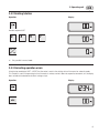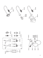
1
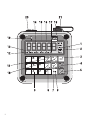
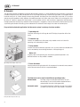
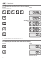
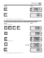
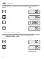
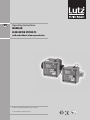
GB GB Operating Instructions Modular flow meter system TS with and without volume preselection Read this operating instructions before start up! To be retained for future reference. 1 ® 2 GB Explanation of the operating unit 1 2 3 4 5 6 7 8 9 10 11 12 13 14 15 16 17 18 19 20 21 Unit of measurement used for flow volume (litres, US-gallons, IMP-gallons). Unit of measurement used for flow rate (l/min, US-G/min, IMP-G/min). Reset key for the displayed flow volume. Start key for filling operation in the automatic mode. Store key to transfer correction factors in the addressable memory. Stop key to interrupt filling operation in the automatic mode. Recall key to display calibration factors from addressable memories. Changeover switch to access the higher-level function in dual-function keys. „S“ 12 is indicated in the display. Switching between manual and automatic mode. In the automatic mode, the word „AUTO“ 13 is indicated in the display. Reduced flow rate. „SLOW“ 16 is indicated in the display. Numerical keypad 0-9. Display of total volume as long as key remains depressed. Activation of calibration mode. „CAL“ 17 is indicated in the display. Display of flow volume in the selected unit of measurement as long as key remains depressed. Key for confirming values (e.g. correction factor, preselected volume). „S“ indicates that the SHIFT key has been pressed, making the higher-level function (in keys no. 4,5,7,8,10,11) effective. „AUTO“ indicates that the flow meter is operating in the automatic mode. „START“ indicates that an automatic filling sequence has been started. „STOP“ indicates that an automatic filling sequence has been interrupted. „SLOW“ indicates that a step-by-step flow reduction has been activated. „CAL“ indicates that the flow meter currently is in the calibration mode. „BATT“ indicates that the batteries require changing. Battery arrangement when changing the batteries. Battery compartment lid. Terminal socket for data line. 3 GB General safety information The operator must read the operating instructions before starting the flow meter and follow these instructions during operation. 1. Note the temperature and pressure limits. The pressure surges produced when closing shutoff valves (valves, slides, etc.) must not exceed the maximum operating pressure. 2. Disconnect the mains power supply and batteries before assembling and dismantling the various modules and the data line. 3. Ensure that all connections and fittings are tight and free from tension. 4. Only alkaline-manganese batteries may be used. 5. Repairs may only be carried out by the manufacturer. The national accident prevention regulations must be observed without fail! When metering flammable liquids according to Directive 67/548/EEC the following must be additionally observed: 1. Only use explosion proof flow meter modules. 2. Before operation, ensure equipotential bonding of the delivery system. 3. Use conductive hoses or pipes. 4. Only use explosion proof relay modules. 5. In explosion hazard areas only use explosion proof plugs. 6. Electrostatic danger due to friction - to be wiped with wet cloth only. Do not use solvents for cleaning. 7. Change of battery only outside of hazardous location with appropriate tools. Only use approved battery types. The national explosion protection regulations must be observed without fail. 4 GB Table of Contents A. General 1. 2. 3. 4. Hazard Safety information Scope of supply Year of construction B. Basic flow meter 1. 2. 3. 4. Proper use 1.1 Application in explosion hazard areas 1.2 Technical data 1.3 Maximum pressure depending on temperature of the medium 1.4 Complete hose system 1.5 Pressure surges (water hammer) 1.6 Pressure drop 1.7 Accuracy of measurement and flow 1.8 Optimization of measurement accuracy by calibration Installation 2.1 Connection for drum pump operation 2.2 Connection to the piping system – Flange connection 2.3 Valve connection Maintenance and servicing 3.1 Cleaning the filter and check valve 3.2 Dismantling the basic flow meter Repairs C. Operating unit 1. Proper use 1.1 Technical data 1.2 Application in explosion hazard areas 1.2.1 Electrical data 2. Installation 2.1 Insert the batteries 2.2 Turning the operating unit 2.3 Separate installation of the operating unit 2.4 Hose installation of the operating unit 3. Operation 3.1 Manual mode 3.1.1 Resetting the part volume meter 3.1.2 Displaying totalizer 3.1.3 Displaying flow rate 3.1.4 Key lock in manual mode 8 9 9 9 9 10 10 10 11 11 12 12 12 13 13 14 14 15 16 16 16 17 17 18 18 18 19 20 21 21 21 22 23 24 24 24 24 24 25 5 GB Table of Contents Automatic mode 25 3.2 3.2.1 Switching between manual and automatic mode 25 3.2.2 Entering the filling volume 26 3.2.3 Starting the filling process 26 3.2.4 Interrupting the filling process 26 3.2.5 Correcting the filling process 27 3.2.6 Stopping the filling process 28 3.2.7 Repeating a preselected volume 28 3.2.8 Cycle counter 29 3.2.9 Filling with step-by-step interruption (SLOW mode) 29 3.2.9.1 Entering/deleting the SLOW volume 29 3.2.9.2 Displaying the SLOW volume 30 3.2.10 System protection through detection of faults 31 3.2.11 Locking function automatic mode 32 Calibration 32 3.3.1 Calibrating through comparative measurement 33 3.3.2 Changing the correction factor in the main memory 34 3.3.3 Displaying the correction factor from the main memory 34 3.3.4 Entering the correction factor into an addressable memory location 35 3.3.5 Displaying the correction factor from an addressable memory location 36 3.3 3.3.6 Copying the correction factor from the main memory into the addressable memory location 36 3.3.7 Copying the correction factor from an addressable memory location into the main memory 37 3.3.8 Calculating of the correction factor in automatic mode 38 Special functions 39 3.4.1 Changing the unit of measurement 39 3.4.1.1 Unit of measurement litres 39 3.4.1.2 Unit of measurement US-gallons 39 3.4.1.3 Unit of measurement IMP-gallons 39 3.4.1.4 Conversion of the flow volume in kilograms via the correction factor 40 Example 40 3.4.2 Deleting totalizer 41 3.4.3 Correcting operation errors 41 3.4 4. 6 Maintenance and servicing 42 4.1 42 Changing the batteries GB Table of Contents D. Relay module RM1/RM3 and mains unit NG1 43 Proper use 43 1.1 Technical data 44 1.2 Application in explosion hazard areas 44 1.2.1 45 1. 2. Electrical data Installation 2.1 Retrofitting the relay module/mains unit 2.2 Connection for automatic mode 46 46 47-49 2.3 Flow meter with separate installation of relay module RM1/mains unit NG1 and operating unit 50 2.4 Flow meter with relay module RM1/mains unit NG1 and separate installation of operating unit 51 3. Maintenance and servicing 52 3.1 52 Changing the fuse in the relay module RM1/mains unit NG1 E. Relay module Ex-RM1m 1. 53 Proper use 53 1.1 53 Technical data 1.1.1 Special conditions (Ex-RM1m B 230 V) 2. Installation 54 54 2.1 Installation location 54 2.2 Dismantling/Assembly 55 2.2.1 Dismantling 55 2.2.2 Assembly 55 Electrical connection 55 2.3.1 Connecting the basic version Ex-RM1m B 230 V 56 2.3.2 Connecting the complete version Ex-RM1m K 230 V 57 3. 2.3 Maintenance and servicing 58 3.1 Changing the fuse 58 F. Repairs 58 G. Traceability 59 H. Annex 59 1. Terminal assignment of cables and connectors 2. Trouble shooting Declaration of Conformity Spare-part list accessories for modular flow meter system 64-67 Spare part list flow meter program 68-71 59 60/61 63 7 GB A. General A. General The flow meter operates according to the positive displacement principle. In a housing fitted with inlet and outlet is a measuring chamber through which the fluid is forced to flow on its way through the housing. In the measuring chamber, a nutating disc blocks the fluid‘s clear path. As it flows through the measuring chamber, the fluid pushes the nutating disc to one side. It is the action of displacing the impediment which produces the wobble movement of the disc and circular motion of the nutating disc shaft. By means of a driver, a magnet with several poles is set into rotation, which is able to activate a magnetically switched contact through the lid of the housing. Every revolution of the nutating disc is assigned to a constant volume and a fixed number of pulses, so permitting the electonic evaluating system to determine the volumetric flow through the number of received pulses. For practically-orientated application, the flow meter system is made up of various modules: Operating unit Electronic evaluating unit with keypad and LCD display for operation of the flow meter. Protection cap Protects the modules basic flow meter, relay module or mains unit when the operating unit is decentrally installed. Relay module Switches the external electrical appliances such as pump motor and solenoid valve and is controlled by the evaluating electronics of the operating unit. Mains unit Supplies power to the operating unit when battery-powered operation is not desired and when no relay module is needed. Operating unit and basic flow meter Basic flow meter Housing and measuring chamber with all components for volumetric measurement which come into contact with the transported medium. The flow meter can be used in two different operating modes: Manual mode: Automatic mode: Relay module and protection cap 8 For filling using a manually operated nozzle. The part volume meter is reset to zero and the required volume is metered while the nozzle is being operated. The preselected volume is filled by pressing a key. Automatic mode is possible only when relay module is connected. A. General GB 1. Hazard The modular flow meter system is developed and built in compliance with the relevant fundamental health- and safety requirements and important EC Directives. Nevertheless, this product can cause danger if it is not used as advised. In case of maloperation or improper use guarantee is excluded and there is danger for • life and health of the user, • the flow meter and other material assets of the user, • the efficiency with the flow meter. All persons who are dealing with the installation/assembly, starting, operation, servicing and maintenance of the flow meter have • to be accordingly qualified, • to observe the local safety and accident preventive rules, • to exactly follow these operating instructions. It is your safety! 2. Safety information In these operating instructions the following symbols are used: Danger! Refers to a direct danger. Non-observance of the precaution will cause death or extremely serious injury. Warning! Defines a possibly dangerous situation. Non-observance of the precaution can cause death or extremely serious injury. Caution! Defines a possibly harmful situation. The product or something in its environment may be damaged if this instruction is not observed. 3. Scope of supply When unpacking the goods, check the articles that: • there is no visible damage from transporting, • the shipped articles, including accessories, are the articles you ordered, • no screws have loosened during transportation. 4. Year of construction The year of construction of the appliance can be seen on the field for the serial number. Here are attached to the serial number the both last digits of the year of construction, e.g. (-10 for the year 2010). 9 GB B. Basic flow meter B. Basic flow meter 1. Proper use The basic flow meter is used for measuring liquid volumes where gauging metering is not required. The basic flow meter is precalibrated for the use of water. The measurement of other pure media is also possible. To do this, a different user-specific calibration factor is entered at the operating unit. Warning! The metering of non-compatible liquids damages the flow meter. Splashing liquid or flying parts can cause injury. Check by means of the materials indicated in the technical data and a resistance table (e. g. Lutz resistance table) whether the basic flow meter is suitable for the delivered liquid. Warning! Exceeding the temperature range and the operating pressure causes damage to the basic flow meter. Splashing liquid or flying parts can cause injury. The ranges indicated in the technical data for temperature of liquid and operating pressure have to be observed. 1.1 Application in explosion hazard areas Application in explosion hazard areas or the metering of flammable liquids can cause explosion resulting in severe injury or death. Following must be observed: • Basic flow meters are non-electrical operating appliances not requiring official approval when used in zone 1. • The basic flow meters VA, HC, LM and UN correspond to the directive 94/9/EC (group II, category 2, for gases and temperature class T4). • The basic flow meter may only be used at atmospherical conditions of 0.8 bar and a temperature range of -20°C up to +40°C . An application is not allowed in atmospheres with flammable dust. • The temperature of the liquid being pumped is limited for types LM and UN to max. 60°C and for types VA and HC to max. 80°C. • An equipotential bonding must be established between basic flow meter, pump tube and hose- or pipe line. • Use only conductive pressure hoses or conductive pipes. • For applications with a drum pump the basic flow meter must be mounted outside of the container. • The admissible operating pressure (type LM, UN - 4 bar and VA, HC - 10 bar) must not be exceeded. • In case another electronical device for analyzing is used than that provided by the manufacturer the explosion protection regulations must be observed. • In order to avoid fire sparkling, assembly works must be carried out by qualified personnel only. • To prevent corrosion it must be ensured that the basic flow meter is resistant to the liquids being transferred. • To prevent an explosive gas atmosphere in the basic flow meter use a solid hose system. Any other use as well as any modifications of the product have to be considered as improper use. The manufacturer will not be held responsable for any damages resulting from such improper use, the risk lies solely with the user. 10 B. Basic flow meter GB 1.2 Technical data Type Flow rate ST min. 10 l/min max. 100 l/min* Temperature 60 °C Viscosity 2000 mPas Operating pressure 4 bar Accuracy ± 1% standard 1% with adjustment to application conditions Inlet port G 2 male thread to fit connector with union nut Outlet port G 1 1/4 male thread Weight 745 g Materials: Housing PPO Measuring PPO/PPS chamber Seals Viton® Magnet BaFe, PA, SS (1.4401) Suitable for no Ex-applications Order No. 0212-100 SL LM UN VA I min. 10 l/min max. 100 l/min* 60 °C 2000 mPas 4 bar ± 1% standard 1% with adjustment to application conditions G 2 male thread to fit connector with union nut G 1 1/4 male thread 780 g min. 10 l/min max. 100 l/min* 60 °C 2000 mPas 4 bar ± 1% standard 1% with adjustment to application conditions G 2 male thread to fit connector with union nut G 1 1/4 male thread 900 g min. 10 l/min max. 100 l/min* 60 °C 2000 mPas 4 bar ± 1% standard 1% with adjustment to application conditions G 2 male thread to fit connector with union nut G 1 1/4 male thread 900 g min. 10 l/min max. 100 l/min 80 °C (60°C**) 5000 mPas*** 10 bar PPO PPO/PPS PPS LCP PPS LCP SS (1.4581) SS/ETFE/ ETFE Viton® PPS encapsulated FEP BaFe, brass, SS yes conductive 0212-300 FEP PPS encapsulated FEP ETFE encapsulated yes conductive 0212-400 yes conductive 0212-500 no 0212-200 ± 1% G 1 1/4 male thread G 1 1/4 male thread 3240 g * short-time 120 l/min. ** in explosion proof version *** depending on the application Description of material ® PPO = Polyphenylene Oxide Viton = Fluoro Elastomer PA = Polyamide PPS = Polyphenylene Sulfide BaFe = Barium-Ferrite FEP = Tetrafluoro Ethylene/Hexafluoro Propylene LCP = Liquid Cristalline Polymere SS = Stainless steel Viton® is a registered Trademark of DuPont Performance Elastomers. 1.3 Maximum pressure depending on temperature of the medium Type VA I, II Type ST, SL, LM, UN Diagram 1 Maximum pressure depending on temperature of the medium 11 GB B. Basic flow meter 1.4 Complete hose system Before initial starting of the flow meter, the entire piping system must be vented from the pump through to the shutoff element (nozzle, solenoid valve or similar). During operation, care must be taken to ensure that the complete system is filled with liquid. 1.5 Pressure surges (water hammer) Considerable pressure fluctuations with so-called water hammer can build up in the system as a result of delays (disconnection/shutoff) or acceleration of the flowing liquid column when using long delivery lines or when using solenoid valves with short opening and closing times. Warning! The brief pressure peaks or surges due to water hammer can cause serious damage and destroy the flow meter, pump or other components in the system! Damage by uncontrolled splashing liquid. Depending on the medium concerned, this can lead to caustic burns, explosion hazards, toxic vapours, electric shocks, danger of slipping and other dangers! Example: A valve closing time of 20 ms can cause a pressure surge of up to 10 bar in a 10 metres long 1" pipe at a flow rate of 50 l/min. Pressure surges can be prevented as follows: •Use a larger nominal diameter (DN) to reduce the flow speed in the delivery line. •Filling with step-by-step interruption (SLOW mode, see chapter C 3.2.9). •Use relief valves and pressure limiting valves to eliminate impermissible pressure peaks. 1.6 Pressure drop Diagram 2 indicates the pressure drop relative to flow. The solid line is applicable for aqueous liquids ( 1 kg/dm³, 1 mPas). In case of media with different density ( 1 kg/dm³) the pressure drop values have to be taken from the solid line in diagram 2 and multiplied by the density value of the liquid. Media with a high dynamic viscosity ( 1 mPas) like high-density media, cause a higher pressure drop. The limiting curve for permissible viscosity at = 1 kg/dm³ is depicted in diagram 2 as a dotted line. If the density is greater than 1 kg/dm³, the pressure drops in the diagram must be multiplied by the actual density. Diagram 2 Pressure drop depending on flow rate. 12 B. Basic flow meter GB 1.7 Accuracy of measurement and flow In the factory the meter is calibrated for a flow rate of 40 l/min. Other flow rates affect the measurement accuracy of the flow meter (see diagram 3). The flow rate may be determined via the SPEED key 11 during the filling process. For adjusting the measuring result to the determined flow rate, the recent correction factor must be called in from the main memory (see chapter C 3.3.3). The recent correction factor then is set off against the volume out of diagram 3 related to the flow rate. Then the new correction factor is entered (see chapter C 3.3.2). Example for type ST, SL, LM, UN Q = 20 l/min Krel = 0.01 K1 = 1.028 K2 = K1 + Krel K2 = 1.028 + 0.01 K2 = 1.038 Example for type VA I: Q = 20 l/min Krel = 0.03 K1 = 3.37 K2 = K1 + Krel K2 = 3.37 + 0.03 K2 = 3.4 Q: Flow rate Krel: Relative correction factor out of diagram 3 K1: Recent correction factor out of main memory K2: New correction factor Diagram 3 Correction factor depending on flow rate 1.8 Optimization of measurement accuracy by calibration When using a flow meter as an automatic batch meter (frequent handling of the same volume), the meter should be calibrated to the operating point. By comparative measurement, the displayed volume is coordinated to the actual volume (see chapter C 3.3.1). For this operating point, the measurement accuracy is 1 digit (corresponding to ± 0.1 litres, ± 0.01 US-G, ± 0.01 IMP-G). 13 GB B. Basic flow meter 2. Installation 2.1 Connection for drum pump operation Mounting steps flow meter type ST, SL, LM and UN: 1. Mount the check valve (option) and filter screen into the inlet (arrow). The non-return valve may be only installed together with a strainer. 2. Insert the o-rings into the collar bush. Wet the sealing surfaces and o-rings with a suitable lubricant. 3. Place the wing nut onto the collar bush 4. Screw the collar bush onto the outlet of the pump tube 5. Screw the wing nut with the flow meter 6. Screw the hose fitting onto the flow meter outlet G 1 1/4 Connection for drum pump operation type ST, SL, LM and UN Mounting steps flow meter type VA I: 1. Insert the seal into the wing nut 2. Screw the drum pump connection onto the outlet of the pump tube 3. Insert the seal into the wing nut and screw it with the flow meter 4. Screw the hose fitting onto the flow meter outlet G 1 1/4 Connection for drum pump operation type VA I 14 B. Basic flow meter GB 2.2 Connection to the piping system – Flange connection Caution! For connecting the flow meter to the piping system, the following must be observed: •Pipes, fittings, etc. must be suitably supported so that additional weight and vibrations are not transmitted to the flow meter! •Suction and discharge lines must always be connected without tension. The piping must be rerouted if an offset cannot be compensated by appropriate means! Mounting steps flow meter type ST, SL, LM and UN 1. Mount the check valve (option) and filter screen into the inlet (arrow) 2. Push the o-ring onto the collar bush. The non-return valve may be only installed together with a strainer. 3. Place the wing nut onto the collar bush and screw it with the flow meter. Wet the sealing surfaces and o-rings with a suitable lubricant. 4. Insert the seals into the screw sockets 5. Screw the screw sockets onto the flow meter and collar bush 6. Insert the seals into the screw sockets 7. Mount the flange 8. Screw on the flanged bush Flange connection type ST, SL, LM and UN Mounting steps flow meter type VA I: 1. Place the flange plate onto the collar bush 2. Insert the seal into the collar bush 3. Screw on the collar bush to the flow meter Flange connection type VA I 15 GB B. Basic flow meter 2.3 Valve connection Mounting steps: 1. Screw the double nipple G 3/4 – G 1 1/4 into the inlet and outlet side of the solenoid valve 2. Mount the hose connection G 1 1/4 on both sides of the hose 3. Connect the hose with the flow meter outlet and the solenoid valve inlet Note flow direction of the solenoid valve! 4. Screw the discharge bend onto the outlet side of the solenoid valve Valve connection 3. Maintenance and servicing 3.1 Cleaning the filter and check valve It is advisable to flush and clean the basic flow meter after handling aggressive, tacky, crystallizing or very contaminating liquids. Procedure type ST, SL, LM and UN 1. Empty the flow meter 2. Release the wing nut 3. Remove the filter and clean with a paintbrush or blow through with compressed air 4. Press in the check valve manually and blow through with compressed air 16 B. Basic flow meter GB 3.2 Dismantling the basic flow meter The basic flow meter can be dismantled for cleaning the measuring chamber or for troubleshooting. Warning! The basic flow meter can still contain liquid during dismantling! In case of aggressive liquids, this can lead to burns, poisoning, irritation of the skin etc. Wear appropriate protective clothing when handling aggressive liquids. Basic flow meter must be emptied before dismantling. Despite of previous emptying, residual liquid can still be in the flow meter housing during dismantling process. Therefore always remove the cover upwards. When dismantling the basic flow meters of type LM, UN and VA it is recommended to replace the o-ring . Wet the sealing surfaces and o-rings with a suitable lubricant. Dismantling the basic flow meters type ST, SL, LM and UN: 1. 2. 3. 4. 5. Release the screws on the bottom side of the flow meter. Remove the cover upwards. Lift the measuring chamber out of the basic body . Remove the o-ring of the measuring chamber. Carefully open the measuring chamber. The assembly is effected in reverse order. When mounting the cover take care of the right position to the basic body . Dismantling the basic flow meter type VA I: 1. 2. 3. 4. 5. Release the screws on the bottom side of the meter. Remove the cover upwards. Remove the clamp . Lift the measuring chamber out of the basic body. Carefully open the measuring chamber. The assembly is effected in reverse order. When mounting the cover take care of the right position to the basic body . 4. Repairs Before sending back the appliance, following must be observed: •Residuals in the appliance can cause danger to the environment and human health. The appliance must be completely emptied, rinsed and cleaned. •Please advise which liquid has been pumped. A respective safety data sheet must be attached to the return consignment. Dismantling the basic flow meter 17 GB C. Operating unit C. Operating unit 1.Proper use Caution! Device failure by corrosion! Use the operating unit BE1 V or Ex-BE1 V for applications in aggressive environments. Caution! The electromagnetic compatibility of the device is compatible with the radiated interference and interference immunity for residential and industrial areas. To avoid interfering influences in a decentralised installation of individual modules, only use data cables from the Lutz company and route the data cables separate from low-voltage lines. 1.1 Technical data Type Display Functions Type of protection Power supply Explosion protection class Use in aggressive areas Electronics Repairs Weight Order No. 18 BE1 BE1 V Ex-BE1 Ex-BE1 V 6-digit LCD-display, 19 mm character height Quantity l, US-G, IMP-G Flow rate l/min, US-G/min, IMP-G/min Change battery, function mode, individual quantity, total quantity, number of filling processes • Reset partial quantity and total quantity • Automatic calibration • Storing differing calibration factors • Lock keys against unauthorised access • Changeover to manual or automatic mode with relay module (optional) • Cycle counter • System protection through detection of faults • Advance cut-out IP 54 in combination with flow meter or optional modules 3 x 1.5 V alkaline manganese batteries or by relay module, mains unit II 2G EEx ib IIB T4 II 2G EEx ib IIB T4 not recommended suitable not recommended suitable replaceable completely potted replaceable completely potted yes no yes no 200 g 300 g 220 g 310 g 0212-001 0212-003 0212-002 0212-004 C. Operating unit GB 1.2 Application in explosion hazard areas Danger! Fire and explosion hazard due to delivered liquid! Combustion hazard. Blast wave: Flying parts can cause death. For measuring inflammable liquids according to Directive 67/548/EEC use operating unit Ex-BE1 or Ex-BE1 V only. Danger! Danger of explosion! Friction causes electrostatic charges! Blast wave: Flying parts can cause death. Operating unit to be wiped with wet cloth only. Danger! Danger of explosion due to inadmissible warming up! Blast wave: Flying parts can cause death. Following electrical data and terminal assignment must be observed. The maximum permissible ambient temperature is: +60° C. Note the temperature of the liquid. 19 GB C. Operating unit 1.2.1 Electrical data Internal power supply 4.5 V (DC); Approved battery types for the power supply: •VARTA Alkaline, No.4001, Size LR1, 1.5V •VARTA High Energy, No.4901, Size LR1, 1.5V •DURACELL Alkaline, Type MN9100, Size N, 1.5V •Energizer Alkaline; Type E90, LR1, 1.5V Change only outside of hazardous location. Module input Explosion protection class intrinsic safety EEx ib IIB; [Socket 1(+), 3(-), 4, 6 or internal plug St1 or St2] Max values: Uo = 5 V Io = 55 mA Po = 68 mW Characteristic curve: linear Ci = 1,1 µF Li unconsidered small Max. admissible outer values for: (following values correspond to the computer program for PTB report ThEx-10) Lo (mH) 2 1 0,5 IIB Co (µF) 16 19 24 when connecting with an active module output in explosion protection class intrinsic safety with max. admissible values: Uo = 6,6 V Io = 165 mA Po = 272 mW Characteristic curve: linear following max. admissible outer values are valid for the connection with the module: (these values correspond to the computer program for PTB report ThEx-10) Lo (mH) 2 1 0,5 20 IIB Co (µF) 6,9 9,9 12 C. Operating unit GB 2. Installation 2.1 Insert the batteries Mounting steps: 1. Unscrew the battery compartment lid 20 2. Remove batteries from styrofoam buffer of packaging 3. Insert batteries, checking for correct polarity 19 4. Screw on the battery compartment lid 20 2.2 Turning the operating unit The operating unit can be turned to the required position in 90°-steps. Mounting steps: 1. Remove cap 2. Release screws 3. Carefully lift the operating unit, paying attention to cable length! 4. Turn the operating unit to the required position 5. Mount the operating unit 6. Fasten the screws hand-tight 7. Mount the cap Turning the operating unit 21 GB C. Operating unit 2.3 Separate installation of the operating unit Due to the modular construction of the flow meter system, it is possible to install the operating unit with or without relay module separately to the flow meter itself. For separate installation, a protection cap, an intermediate plate and a data line are required. Mounting steps: 1. Remove batteries out of the operating unit 2. Remove the cap and release the screws 3. Carefully lift the operating unit, paying attention to cable length! 4. Release the plug 5. Remove the cap from the intermediate plate 6. Screw the intermediate plate onto a base (screws not included in the scope of supply) 7. Mount the cap 8. Screw the operating unit onto the intermediate plate and mount the cap 9. Connect the ribbon cable to the plug in the protection cap 10. Screw the protection cap onto the flow meter and mount the cap 11. Connect the operating unit and protection cap using the data line 12. Insert the batteries Caution! Fasten the screws only handtight. Separate installation of the operating unit 22 C. Operating unit GB 2.4 Hose installation of the operating unit Mounting steps: 1. Remove the batteries out of the operating unit 2. Remove the cap and release the screws 3. Carefully lift the operating unit, paying attention to cable length! 4. Release the plug 5. Remove the cap from the intermediate plate 6. Screw the hose clamps under the intermediate plate and mount the cap 7. Screw the operating unit onto the intermediate plate and mount the cap 8. Press the hose into the hose clamps. Snap the clamp into place 9. Connect the ribbon cable to the plug in the protection cap 10. Screw the protection cap onto the flow meter and mount the cap 11. Connect the operating unit and protection cap using the data line 12. Insert the batteries Caution! Fasten the screws only handtight. Assembly of the operating unit at the hose 23 GB C. Operating unit 3. Operation Following described key sequences must be pressed step by step. 3.1 Manual mode In manual mode, the filling process is carried out using a manually operated nozzle. The part volume meter is reset to zero and the required volume is metered. 3.1.1 Resetting the part volume meter Operation Display Only possible in manual mode 3.1.2 Displaying totalizer The totalizer adds all individual metering processes carried out in the manual or automatic mode. Operation Display The total volume appears as long as the key is depressed. 3.1.3 Displaying flow rate Operation Display 24 The total flow rate appears as long as the key SPEED is depressed. The flow rate is displayed in the selected volume unit per minute. C. Operating unit GB 3.1.4 Key lock in manual mode Avoiding maloperations – as inadvertent calibration – all keys, except RESET, SPEED and TOT can be locked. Operation Display The key lock appears in the display L. The key lock also remains if there is no power supply (battery). Releasing the key lock, press the key RESET and repeat the combination above. 3.2 Automatic mode In automatic mode, a preselected volume can be repeatedly filled by pressing a key. To permit this function a relay module and a solenoid valve are required in addition to the flow meter (for installation see chapter D 2.2). 3.2.1 Switching between manual and automatic mode Operation Display Switching from automatic to manual mode is carried out in the same way. The display AUTO disappears. Switching between manual and automatic mode is only possible if a relay module is connected. 25 GB C. Operating unit 3.2.2 Entering the filling volume Operation Display Enter filling volume e.g. 50 LITRES The entered filling volume flashes Complete the input by pressing the ENTER key. To correct the filling volume, the input must have been completed (by pressing ENTER). It is then possible to enter a new filling volume. 3.2.3 Starting the filling process Operation Display The process runs through to the end. It can be interrupted at will and restarted. 0.0 appears on the display when the process has been completed correctly. 3.2.4 Interrupting the filling process Operation Display 26 The filling process is resumed by pressing START (see chapter C 3.2.3). If the filling process is interrupted by the system without any apparent reason, there is a fault in the system and the self-protection device has been activated (remedy the fault). C. Operating unit GB 3.2.5 Correcting the filling process During the filling process, it is possible to correct the filling volume. In this case, the already transported volume is offset against the new filling volume. Operation Display Enter filling volume e.g. 50 LITRES The entered filling volume flashes Display static Enter filling volume e.g. 30 LITRES continued on next page 27 GB C. Operating unit Operation Display The entered filling volume flashes The correction process is only successful if the new filling volume is greater than the volume which has already been transported. 3.2.6 Stopping filling process Operation Display It is possible to make a new input (see chapter C 3.2.2) or to repeat the current filling volume using the RESET key (3). 3.2.7 Repeating a preselected volume Operation Display Filling volume flashes 28 The entered filling volume flashes The filling process can be started (see chapter C 3.2.3). C. Operating unit GB 3.2.8 Cycle counter The cycle counter registers the number of filling cycles with the same volume filled. This means that the user does not have to count the cycles, e.g. when 100 containers have to be filled with the same volume. The cycle counter starts at zero again when a new filling volume is entered. Interrupted filling processes are not counted. Changing the SLOW quantity has no effect on the cycle counter. Operation Display The cycle counter is displayed as long as the key is depressed. It cannot be displayed while filling is in process. 3.2.9 Filling with step-by-step interruption (SLOW mode) In the automatic mode, it is possible to carry out the filling process using two different flow volumes. This is particularly useful for fast, precise filling of large quantities, or when transporting a foaming medium. Two solenoid valves arranged in parallel are required for this process. The valves are closed at different times, so reducing pressure surges in the system, and helping to avoid overflowing when transporting foam-forming media. A throttle element, such as a ball valve in line with the valve disconnected last, to regulate the flow volume is beneficial. The reduced flow speed volume is entered using the SLOW function. 3.2.9.1 Entering/deleting the SLOW volume Operation Display Filling volume flashes Actual SLOW volume flashes continued on next page 29 GB C. Operating unit Operation Display Enter slow volume, e.g. 1 litre (for deleting enter 0) If the SLOW volume is greater than the intended filling volume, the main valve remains closed during the entire filling process. Only possible in the automatic mode 3.2.9.2 Displaying the SLOW volume Operation Display 30 Only possible in the automatic mode C. Operating unit GB 3.2.10 System protection through detection of faults The filling process can be controlled automatically by the flow meter, since faults may develop in the connecting lines, such as running dry, blockages, defective solenoid valves, etc. When the START key is pressed, the flow meter monitors the time during which no liquid is registered. The flow meter switches off when a certain time limit is exceeded. STOP appears on the display. The interruped filling process can be resumed by pressing START again when the fault has been remedied. The monitoring time can be freely selected between 1 and 999 seconds. A time of 3 seconds is set by the manufacturer. The monitoring function is deactivated by entering 0. The monitoring time can only be changed in manual mode. Operation Display Enter the monitoring time, e.g. 5 seconds (enter 0 to deactivate the function) continued on next page 31 GB C. Operating unit Operation Display The new monitoring time flashes 3.2.11 Locking function automatic mode The locking function in automatic mode makes it impossible to change over to manual mode and prevents inadvertent input of a new filling volume. This helps to prevent operator errors when filling always the same volumes. The following functions remain active even when the keypad is locked: RESET, START, STOP, totalizer (TOT), display flow rate (SPEED) and cycle counter (see chapter C 3.2.8). Operation Display The key lock appears in the display L. The key lock also remains if there is no power supply. The above combination must be entered again in order to deactivate the locking function. 3.3 Calibration In the factory the meter is calibrated for the medium water transported at a mean flow rate of 40 l/min. Various operating conditions such as slower flow rates or the transportation of media with greater viscosity can result in measurement inaccuracy (see chapter B 1.6). To adjust to these operating conditions, a changeable correction factor can be used to recalibrate the flow meter in manual mode. The correction factor is either entered directly or the electronic evaluating unit calculates the right correction factor according to a comparative measurement between the displayed and the actual filled volume. The flow meter is also equipped with nine addressable memory locations (memory numbers 1-9), in which already ascertained correction factors can be stored and copied to the main memory (memory number 0) if required. 32 C. Operating unit GB 3.3.1 Calibration through comparative measurement Operation Display Fill the volume into a measurement vessel Read the value on the measurement vessel and enter at numerical keypad Calculated correction factor flashes In automatic mode input is not possible (see chapter C 3.2.1). 33 GB C. Operating unit 3.3.2 Changing the correction factor in the main memory Operation Display Entering the correction factor In automatic mode input is not possible (see chapter C 3.2.1). 3.3.3 Displaying the correction factor from the main memory Operation Display continued on next page 34 C. Operating unit GB Operation Display In automatic mode input is not possible (see chapter C 3.2.1). 3.3.4 Entering the correction factor into an addressable memory location Operation Display Entering the correction factor Entering the memory number In automatic mode input is not possible (see chapter C 3.2.1). 35 GB C. Operating unit 3.3.5 Displaying the correction factor from an addressable memory location Operation Display Entering the memory number In automatic mode input is not possible (see chapter C 3.2.1). 3.3.6 Copying the correction factor from the main memory into the addressable memory location Operation Display continued on next page 36 C. Operating unit GB Operation Display Entering the memory number In automatic mode input is not possible (see chapter C 3.2.1). 3.3.7 Copying the correction factor from an addressable memory location into the main memory Operation Display Entering the memory number continued on next page 37 GB C. Operating unit Operation Display In automatic mode input is not possible (see chapter C 3.2.1). 3.3.8 Calculation of the correction factor in automatic mode In the automatic mode direct calibration is not possible. However, the possibility of filling a preselected quantity into a measuring vessel and calculating the new correction factor then is given. Following steps are required: • Enter filling volume (see chapter C 3.2.2) • Start filling process (see chapter C 3.2.3) • Change into manual mode at the end of filling process (see chapter C 3.2.1) • Have correction factor displayed from the main memory (see chapter C 3.3.3) • Calculate new correction factor according to the below formula k2 = k1 k2 VV VM : : : : VM k 1 VV Correction factor from the main memory New correction factor Preselected volume Read volume in measuring vessel • Enter calculated correction factor into the main memory (see chapter C 3.3.2) 38 C. Operating unit GB 3.4 Special functions 3.4.1 Changing the unit of measurement In manual mode the flow meter can be switched between the units of measurement litres, US-gallons and IMP-gallons without altering the calibration. 3.4.1.1 Unit of measurement litres Operation Display Number sequence 0123 Only possible in manual mode 3.4.1.2 Unit of measurement US-gallons Operation Display Number sequence 0456 Only possible in manual mode 3.4.1.3 Unit of measurement IMP-gallons Operation Display Number sequence 0789 Only possible in manual mode 39 GB C. Operating unit 3.4.1.4 Conversion of the flow volume in kilograms via the correction factor For special applications, the flow meter is able to display the measured volume in a unit of mass such as kilograms. The correlation between volume V and mass m is ascertained using density . m=ρ•V If the correction factor for volume measurement is known (see chapter C 3.3.1 or correction factor diagram 3), this is offset with the density . Convert the correction factor according to the below formula k1 :Correction factor after calibration k2 = ρ • k1 k2 :Correction factor for display of the unit of mass :Fluid density Example Operation Display Enter the calculated correction factor k2 The entered correction factor flashes The entered correction factor flashes 40 The unit of volume (litres or gallons) displayed on the flow meter is now no longer valid. Recommendation: Cover over the displayed unit of volume using a foil indicating the valid unit of mass. C. Operating unit GB 3.4.2 Deleting totalizer Operation Display Number sequence 0357 Only possible in manual mode 3.4.3 Correcting operation errors Using the key combination SHIFT + RESET, the flow meter is reset to the starting status of the manual or automatic mode. This function is useful if the operating status of the meter is unclear, or when it does not respond to commands, or if the display does not indicate the desired result when making an input. Operation Display 41 GB C. Operating unit 4. Maintenance and servicing 4.1 Changing the batteries The flow meter is running on 3 alkaline manganese batteries LR 1, SIZE N. The LCD display indicates the approaching end of the battery life with the word „BATT“ 18. If the „BATT“ display flashes, the batteries must be changed within 1-2 weeks. Once the „BATT“ display is indicated permanently, the batteries require immediate changing. Danger! When changing the batteries in explosion hazard areas danger of explosion occurs! Blast wave: Flying parts can cause death. Change of battery only outside of hazardous location with appropriate tools. Only following battery types are approved: • VARTA High Energy; No. 4901; Size LR1 • VARTA Electronic Alkaline; No. 4001; LR1; LADY; N; AM5 • DURACELL ALKALINE; SIZE N; MN9100; LR1 • Energizer Alkaline; E90; LR1; N Mounting steps: 1. Unscrew the battery compartment lid 20 2. Remove the batteries 3. Insert new batteries, checking for correct polarity 19 4. Screw the battery compartment lid 20 5. Press key RESET If the flow meter is not used for longer periods, the batteries must be removed! Environment protection Batteries and battery packs are containing dangerous substances for the environment and the human health. Do not dispose batteries and battery packs into the domestic waste, into fire or into water. Batteries and battery packs must be collected and recycled. Within the EC countries you are legally bound to return batteries and battery packs after use to the sale shop or a public collecting point. Taking back of batteries and battery packs is free of charge. 42 D. Relay module RM1/RM3 and mains unit NG1 GB D. Relay module RM1/RM3 and mains unit NG1 1. Proper use For automatic mode (preselected volume), the relay module is required alongside the basic flow meter and operating unit modules. The relay module is controlled by the evaluating electronics of the operating unit and switches the external electrical appliances such as pump motor and solenoid valve. The electrical connection between the operating unit and relay module is effected by means of a 10-core ribbon cable. The relay module RM1/RM3 or the mains unit NG1 includes a power supply for the operating unit. The batteries only then have a buffer function in the event of a power failure. The relay module RM1 and RM3 are fitted with three sockets permitting the connection of external appliances , and the power supply . The mains unit NG1 is fitted only with a connection for the power supply . Relay module Danger! Live mains connection! Electric shocks can cause death. An operating unit or a protection cap must be mounted to the relay modules RM1, RM3 or to the mains unit NG1 as protection against touching and contact with water. Caution! The electromagnetic compatibility of the device is compatible with the emitted interference and interference immunity for residential and industrial areas. To avoid interfering influences in a decentralised installation of individual modules, only use data cables from the Lutz company and route the data cables separate from low-voltage lines. 43 GB D. Relay module RM1/RM3 and mains unit NG1 1.1 Technical data Type Voltage Frequency Switching outputs Pump switching current Solenoid valve switching current Type of protection Explosion protection class Connections Weight Order No. RM1 230 V 220-240 V RM1 120 V RM3 400/230 V 110-125 V 230/400 V 50 – 60 Hz 2 switching outputs (potentially bound) 4 A, cos > 0,7 8,5 A, cosj > 0,7 0,5 A II 2G [EEx ib] IIC 16 A, cosj > 0,7 NG1 230 V 220-240 V – – – IP 44 – – – 634 g 0212-060 290 g 0212-090 round connector 440 g 0212-020 430 g 0212-030 1.2 Application in explosion hazard areas Danger! Danger of explosion! Combustion hazard. Blast wave: Flying parts can cause death. The relay module RM1, the mains unit NG1 and the connecting cables are not suitable for use in explosion hazard areas! If the relay module itself is not located in an explosion hazard area the relay module RM1 230 V may supply the power and signals to the operating unit in zone 1. For this application the relay module must be used with an ambient temperature of -20 up to +40°C. This temperature range is also applied to the measured liquid when the relay module is mounted on the basic flow meter. 44 D. Relay module RM1/RM3 and mains unit NG1 GB 1.2.1 Electrical data Input: (ST3) U Imax cos ϕ Pmax = 220 - 240 V ~ = 8A > 0,7 = 1760 - 1920 W Output: Output 1 (Pump): (ST4 and ST5) U Imax cos ϕ Pmax = 220 - 240 V ~ = 4A > 0,7 = 880 - 960 W Output 2 (Valve): (ST4 and ST5) U Imax cos ϕ Pmax = 220 - 240 V ~ = 0,5 A > 0,7 = 77 - 84 W Output intrinsic safety: (ST1 or ST2) U I P = 6,6 V = = 165 mA = 272 mW Max. admissible outer values for: L (mH) 2 1 0,5 0,2 0,1 C (mF) 1 1,6 2,2 3 3,8 45 GB D. Relay module RM1/RM3 and mains unit NG1 2. Installation 2.1 Retrofitting the relay module/mains unit Mounting steps: 1. Remove batteries out of the operating unit 2. Remove the cap and release the screws 3. Carefully lift the operating unit, paying attention to cable length! 4. Release the plug 5. Plug the connector in the socket on the underside of the intermediate plate 6. Carefully mount the intermediate plate in the desired position and tighten up the screws 7. Plug the connecting cable in the socket on the topside of the intermediate plate and on the circuit board of the relay module/mains unit 8. Mount the relay module/mains unit onto the intermediate plate 9. Plug the ribbon cable of the relay module/mains unit into the socket on the circuit board of the operating unit 10. Mount the relay module/mains unit onto the intermediate plate 11. Tighten the screws and replace the cap 12. Insert the batteries Caution! Fasten the screws only handtight. 46 Retrofitting of the relay module D. Relay module RM1/RM3 and mains unit NG1 GB 2.2 Connection for automatic mode A number of ready-configured cables are available for connecting up external units: Power supply cable relay module RM1/mains unit NG1, 5 m long (Order No. 0211-155) Connecting cable main valve, 5 m long (Order No. 0211-150) For actuation of a solenoid valve via the relay module RM1or RM3. Connecting cable SLOW-valve, 5 m long (Order No. 0211-151) Using this cable, a second solenoid valve can be actuated in conjunction with the cable set motor/SLOW, 3-way. Connecting cable motor/SLOW 1-way, 0.5 m long (Order No. 0211-153) To actuate a pump motor or second solenoid valve via the relay module RM1. Connecting cable motor/SLOW 3-way, 0.5 m long (Order No. 0211-154) This cable is required for connection of 3 external appliances such as motor and two solenoid valves. Power supply cable RM3 230 V, 5 m long (Order No. 0211-387) For A.C. power supply of the relay module RM3. Connecting cable motor 230 V, 0.5 m long (Order No. 0211-385) For actuation of an A.C. driven pump motor via the relay module RM3. Power supply cable RM3 400 V, 5 m long (Order No. 0211-388) For 3-phase current power supply of the relay module RM3. Connecting cable motor 400 V, 0.5 m long (Order No. 0211-386) For actuation of a 3-phase current driven pump motor via the relay module RM3 Extension cable, 5 m long (Order No. 0211-152) (without illustration.) For extension of the connecting cables ,,,. 47 GB D. Relay module RM1/RM3 and mains unit NG1 Relay module RM1: Connection of pump motor and solenoid valve Relay module RM1: Connection of pump motor, main valve and SLOW valve 48 D. Relay module RM1/RM3 and mains unit NG1 GB Relay module RM3: Connection of pump motor (AC) and solenoid valve Relay module RM3: Connection of pump motor (3-phase current) and solenoid valve 49 GB D. Relay module RM1/RM3 and mains unit NG1 2.3 Flow meter with separate installation of relay module/mains unit and operating unit Danger: Live mains connection! Electric shocks can kill you. Disconnect the relay module/ mains unit by pulling the plug from the power supply before dismantling! Mounting steps: 1. Remove batteries out of the operating unit 2. Remove the cap and release the screws 3. Carefully lift the operating unit and relay module/mains unit, paying attention to cable length! 4. Loosen the connector from the intermediate plate 5. Unscrew the intermediate plate 6. Carefully remove the intermediate plate, paying attention to cable length! 7. Loosen the connector from the intermediate plate 8. Remove the cap from the intermediate plate 9. Screw the intermediate plate onto a base (screws not included in the scope of supply) 10.Mount the cap 11.Insulate the intermediate plate using the cap 12.Screw the operating unit and relay module/mains unit onto the intermediate plate and mount the cap 13.Connect the ribbon cable to the plug in the protection cap 14.Screw the protection cap onto the flow meter and mount the cap 15.Connect the operating unit and protection cap using the data line 16. Insert the batteries Caution! Fasten the screws only handtight. 50 Separate installation of relay module/mains unit and operating unit D. Relay module RM1/RM3 and mains unit NG1 GB 2.4 Flow meter with relay module/mains unit and separate installation of operating unit Danger! Live mains connection! Electric shocks can kill you. Disconnect the relay module/ mains unit by pulling the plug from the power supply before dismantling! Mounting steps: 1. Remove batteries out of the operating unit 2. Remove the cap and release the screws 3. Carefully lift the operating unit, paying attention to cable length! 4. Loosen the connector from the circuit board of the operating unit 5. Remove the cap from the intermediate plate 6. Screw the intermediate plate onto a base (screws not included in the scope of supply) 7. Mount the cap 8. Mount the operating unit on the intermediate plate using the short screws supplied with the protection cap, and then mount the cap 9. Connect up the cable between the relay module/mains unit and the protection cap 10.Screw the protection cap and relay module/mains unit onto the flow meter using the long screws and replace the cap 11.Connect the operating unit and protection cap using the data line 12.Insert the batteries Caution! Fasten the screws only handtight. Separate installation of the operating unit 51 GB D. Relay module RM1/RM3 and mains unit NG1 3. Maintenance and servicing 3.1 Changing the fuse in the relay module/mains unit Danger! Live mains connection! Electric shocks can kill you. Disconnect the relay module / mains unit by pulling the plug from the power supply before dismantling! Danger! Danger of explosion from short circuit! Combustion hazard. Blast wave: Flying parts can kill you. Only use the types of fuses listed below. The unit can be damaged and the explosion protection is at risk if higher fusing ratings are used. As the blowing of a fuse generally precedes a fault, have the unit checked by an electrical specialist before changing a fuse. The units are adequately protected when 5 x 20 mm IEC 127 finewire fuses are used: Power supply SI3: Motor connection SI1: Valve output SI2: 1. 2. 3. 4. 5. 6. 7. 8. 52 RM1 230 V 0,1 A semi time-lag (mT) 4 A time-lag (T) RM1 120 V 0,1 A semi time-lag (mT) 6,3 A time-lag (T) 0,5 A semi time-lag (mT) 0,5 A semi time-lag (mT) RM3 0,1 A semi time-lag (mT) fuse protection by mains supply with max. 16 A 0,5 A semi time-lag (mT) NG1 230 V 0,1 A semi time-lag (mT) – Pull out the plug of the relay module/mains unit Remove the cap and release the screws Carefully lift the operating unit/protection cap and relay module/mains unit, paying attention to cable length! Release the reed contact plug Check the finewire fuses and replace if necessary Connect the reed contact plug Mount the relay module/mains unit with operating unit/protection cap onto the flow meter Tighten the screws and replace the cap – E. Relay module Ex-RM1m GB E. Relay module Ex-RM1m 1. Proper use For automatic mode (preselected volume), the relay module is required alongside the basic flow meter and operating unit modules. The relay module is controlled by the evaluating electronics of the operating unit and switches the external electrical appliances such as pump motor and solenoid valve. The electrical connection between the operating unit and relay module is effected by means of a 10-core ribbon cable. The relay module Ex-RM1m includes a power supply for the operating unit. The batteries only then have a buffer function in the event of a power failure. The relay module Ex-RM1m is supplied in two versions. • The basic version of the Ex-RM1m B 230 V is without fuses, cable glands or cabling for customer-specific applications. Particular attention shall be paid in the following chapters to the requirements on components not included in the scope of supply. • The full version Ex-RM1m K 230 V includes cable glands, 5 m power supply cable with Ex-plug, fusing elements and Ex-flange boxes for pump and valve. The relay module Ex-RM1m consists of three housing parts. The upper section houses the potted electronics. The lower section is designed as the connection compartment in the method of explosion protection „e“ for greater safety. The connections are made here for the power supply, pump and the solenoid valve. The lower housing connection constitutes an intermediate plate so that it can be mounted to the lower body of the flow meter or to any permanent base (e.g. wall, mounting plate). The upper connection of the relay module forms part of a further module from the system. 1.1 Technical data Danger! Fire and explosion hazard due to electric current. Combustion hazard. Blast wave: Flying parts can kill you. Compliance with the following electrical characteristics is required. Type Voltage Input supply terminals 1+2 Switching outputs Output 1 (Pump) terminals 3+5 Output 2 (Valve) terminals 4+5 Type of protection Explosion protection class Connections Electronics Accessories Weight Order No. Ex-RM1m B 230 V Ex-RM1m K 230 V 220 - 240 V, 50 – 60 Hz max. 8 A, cos > 0,7 max. 1760-1920 W 2 switching outputs (potentially bound) max. 4 A, fuse on construction side, 4 A fuse, cos > 0,7 cos > 0,7, max. 880-960 W max. 880-960 W max. 4 A, fuse on construction side, 0,5 A fuse cos > 0,7, max. 880-960 W max. 110–120 W IP 54 II 2G EEx me[ib] IIC T4 terminal block, no screw completely potted Full version with fuses, Basic version without fuses, cable glands and cables. cable glands, 5 m mains connecting For customer specific applications. cable with Ex-plug, Ex-flange boxes for pump and valve 1000 g 3000 g 0212-040 0212-050 53 GB E. Relay module Ex-RM1m 1.1.1 Special conditions (Ex-RM1m B 230 V) As a protection against short circuits, a fusing of appropriate rating (max. 3 x IB according to DIN 41571 or IEC 127) for the designed current rating, or a starting circuit-breaker with short-circuit and instantaneous thermal (set to the design current) release, must be connected in series for each relay module Ex-RM1. This fuse either can be positioned in the appropriate power supply or has to be connected before the device. The fuse-design current must be equal to or greater than the given voltage rating for the relay module. The breaking capacity of the fuse used must be equal to or greater than the maximum short-circuit current (normally 1500 A) that can be assumed for the location of installation. If the pump and the valve are protected in the connecting compartment of the relay module from short circuits, then the design voltage for the fuse must be equal to or greater than the given voltage rating for the pump or valve. The breaking capacity of the fuse used must be equal to or greater than the maximum short-circuit current (normally 1500 A) that can be assumed for the location of installation. If the breaking capacity of the installed fuse differs from this, then the value for the maximum admissible short-circuit current shall be indicated on the relay module. For applications in explosion hazard areas, all persons who are responsible for the installation must be accordingly qualified for these works. 2. Installation 2.1 Installation location The relay module Ex-RM1m can be mounted to the lower body of the flow meter or to any permanent base (e.g. wall, mounting plate). The upper connection of the relay module forms part of a further module from the system. The completely mounted system meets the requirements of protection class IP 54. Caution! The electromagnetic compatibility of the device is compatible with the emitted interference and interference immunity for residential and industrial areas. To avoid interfering influences in a decentralised installation of individual modules, only use data cables from the Lutz company and route the data cables separate from low-voltage lines. 54 E. Relay module Ex-RM1m GB 2.2 Dismantling/Assembly 2.2.1 Dismantling 1. 2. 3. 4. 5. 6. 7. Remove the cap Release the screws Carefully lift off the top module and pull off the connector Carefully lift off the relay module and pull off the connector Release the screws Carefully lift off the intermediate plate and pull off the connector Take out the screws with washers from the groove in the intermediate plate 2.2.2 Assembly Caution! Pinching the electrical leads can damage the unit. When assembling the unit, do not route electrical connections at points where these can be pinched. 8. Insert the screws and washers in the groove of the intermediate plate . Screws to be used: Stainless steel flow meter – screws with metric threads / plastic flow meter – screws with cutting threads 9. Plug in the connector and carefully mount the intermediate plate such that the points on the intermediate plate coincide with the points on the relay module 10. Tighten the screws 11. Insert the connector and carefully mount the relay module 12. Insert the connector and carefully mount the top module in the desired position 13. Tighten the screws 14. Insert the cap Caution! Fasten the screws only hand-tight. 2.3 Electrical connection Danger! Live mains connection! Electric shocks can kill you. The electrical connections may only be carried out by qualified personnel – a trained electrician. The power supply shall be disconnected and prevented from accidental re-connection throughout duration of the work. Ensure before connecting the relay module that: • • • • • • • The values for voltage and frequency given on the nameplate agree with the data for the mains. The mains connection is fused in accordance with chapter E 1.1 and 1.1.1 All poles of the mains connection have been disconnected when permanently connecting the relay module. Atex-approved cable protection covers of protection class IP 54 are used. Metal cable entries with grounding tongues connected to the protective conductor. Cables of the design HO7RN-F 3G1.5 are used. All cable protection covers which are not needed are sealed according to protection class IP 54. 55 GB E. Relay module Ex-RM1m 2.3.1 Connecting the basic version Ex-RM1m B 230 V The electrical connection between the mains, the pump and solenoid valve is made in the connecting compartment on the underside of the relay module. The relay module Ex-RM1m must be dismantled in accordance with steps 1-4 of chapter E 2.2.1 when the flow meter system is mounted. The electrical connection is made in accordance with the following circuit diagram: Refer to chapter E 1.1 (Technical data) when making electrical connections 56 E. Relay module Ex-RM1m GB 2.3.2 Connecting the complete version Ex-RM1m K 230 V The electrical connection is made using explosion proof plug-in connections. The mains is connected to the explosion proof plug (CEAG). The maximum rating of the fuse for mains outlet socket shall be 16 A. Pump and solenoid valve are connected to the two flange boxes of the relay module with plug system eXLink (CEAG) or mini CLIX (steel). Maximum load: Pump 4 A, solenoild valve 0.5 A. 57 GB E. Relay module Ex-RM1m / F. Repairs 3. Maintenance and servicing 3.1 Changing the fuse The relay module Ex-RM1m in the full version Ex-RM1m K 230 V includes two fusing elements to protect the outputs for pump and solenoid valve in the connecting compartment. Pump: Fusing element Ex 4 A semi time-lag Solenoid valve: Fusing element Ex 500 mA semi time-lag Danger! Live mains connection! Electric shocks can kill you. Replacing the fuse may only be carried out by qualified personnel – a trained electrician. The power supply shall be disconnected and prevented from accidental re-connection throughout duration of the work. As the blowing of a fuse generally precedes a fault, have the unit checked before changing the fusing elements. Danger! Fire and explosion hazard due to electric current. Combustion hazard. Blast wave: Flying parts can kill you. Use only original fusing elements. 1. To replace the fuses, dismantle the relay module in accordance with steps 1-4 of chapter E 2.2.1 2. Disconnect the defective fusing element and remove from the top hat rail. 3. Snap a new fusing element onto the top hat rail and connect. 4. Mount the relay module in accordance with steps 11-14 of chapter E 2.2.2 F. Repairs Repairs should only be made by the manufacturer or authorized Lutz-dealers. Only use original Lutz spare parts. 58 G. Traceability / H. Annex GB G. Traceability Products manufactured by Lutz-Pumpen for potentially explosives atmospheres are identified by an individual batch number which allows them to be traced. This number provides the year of construction and the design of the equipment. This product is an appliance for potentially explosive atmospheres. In this regard and in compliance with the EC ATEX 94/9 Directive, provisions must be made to ensure ascending and descending traceability. Our ATEX notified quality system ensures this traceability up to the initial point of delivery. Except as otherwise agreed in writing, anyone that guarantees to redeliver said equipment undertakes to put in place a system that allows for equipment that is not conform to be recalled if necessary. H. Annex 1. Terminal assignment of cables and connectors 1 2 3 4 5 Plus (Battery approx. 4.5 V, Relay module approx. 5 V) Counting impulse Minus Relay pump Not in use 6 Relay valve 7 Not in use Data outlet operating unit Terminal assignment of data line RM1 1 + 2 3 110-230V / 50-60 Hz Not in use Earth conductor Relay module RM 1- mains connection 1 2 3 4 PE Ex-RM1m Neutral conductor Pump motor / SLOW-Valve Main valve Not in use Earth conductor Relay module RM 1 - connection of external electrical appliances 59 60 Automatic mode Manual mode Operating mode General No liquid registered Filling process interrupted by flow meter "STOP" appears on display "Batt" indication flashes or remains permanently on No indication after changing batteries Throughput decreases Liquid leaks from the housing Fault No liquid registered Measured quantity differs significantly from the actual quantity Solenoid valve does not open Time required to fill the connecting lines exceeds the set monitoring time Batteries fitted incorrectly Battery contacts corroded Dry running End of battery service life Seal defective Hairline cracks in housing and/or on screw connection due to mechanical influences Screw connection not tightened securely Operating pressure exceeded, pressure surges e.g. due to water hammer Inadequate chemical resistance Filter screen soiled Measuring chamber soiled Leaks in hose system Radio interference on the data line Cause Correction factor 0 in the main memory Correction factor does not match operating conditions Wrong unit of measure set Open battery compartment and check polarity Clean contacts Prevent air pockets in connecting lines, use a solid hose system Check solenoid valve Increase monitoring time (chapter C 3.2.10) Contact manufacturer Remove and clean filter screen Flow meter must be flushed and cleaned regularly after handling aggressive, tacky,crystallizing or very contaminating liquids Replace batteries (chapter C 4.1) Set correct unit of measure (chapter 3.4.1) Install check valve if necessary Place data line separate from low-voltage conduits Replace seal Check installation conditions for mechanical stresses and correct them Check that screw connections are secure Check pressure conditions Remedy Calibrate flow meter (chapter C 3.3) Calibrate flow meter (chapter C 3.3) 2. Trouble shooting 61 Separate installation of operating unit and/or relay module Operating mode Automatic mode Occasional transmission errors Display OK, but operator inputs impossibe Pump motor will not start, solenoid valve switches Data line exposed to strong electromagnetic fields (large machines, power cables, etc.) Data line defective SLOW value exceeds entered filling volume Motor switched off Pump motor with low voltage release switches off automatically Cable connection interrupted Cause Swash plate blocked Fuse in relay module defective No liquid delivered after starting, 0.0 appears Correction factor too high on display Solenoid valve does not operate, pump is Cable connection interrupted running Fuse in relay module defective Solenoid valve blocked Fault Check connecting cable and secure fit of plug connections (chapter D 2.2) Data line must be shielded against electromagnetic interference Check data line for damage and secure fit of plug connection (chapter D 2.3 and 2.4) Reduce SLOW value (chapter C 3.2.9) Switch on motor Use pump motor without low voltage release Remedy Clean flow meter, check resistance Check fuses (chapter D or E 3.1) Reduce correction factor, recalibrate flow meter Check connecting cable and secure fit of plug connections (chapter D 2.2) Check fuses (chapter D or E 3.1) Check solenoid valve and clean if necessary GB 62 Lutz Pumpen GmbH Erlenstraße 5-7 D-97877 Wertheim Declaration of Conformity Herewith we declare that the below-mentioned machine in it‘s conception and design and in the execution marketed by us fully complies with the EC directives. This declaration ceases to be valid if the machine is modified in any way without prior consultation with us. Type of device: Modular Flow Meter System Basic flow meter HC Basic flow meter VA I Basic flow meter UN Relay module RM1 120V Basic flow meter LM Relay module RM1 230V Mains unit NG1 230V Operating unit Ex-BE1 V Relay module RM3 400/230V Operating unit Ex-BE1 Applicable EC Directives: Operating unit BE1 V Operating unit BE1 EC Directive on low voltage installations (2006/95/EC) EC-Directive EMV (2004/108/EC) EC-Directive ATEX (94/9/EC) EC-Type examination PTB 00 ATEX 2135 X PTB 0102, EC-Type examination Bundesallee 100, 38116 Braunschweig PTB 01 ATEX 2204 EC-Type examination PTB 03 ATEX 2093 Registered number 05 ATEX D136 Identification: II 2G T4 EN 1127 EN 13463-1 EN 13463-5 EN 60079-0 Applicable EN 60079-7 harmonized EN 60079-11 standards EN 60079-18 EN 55014 EN 61000-3-2 EN 50082-2 Relay module Ex-RM1m 230V Module: Wertheim, 10.05.2010 Jürgen Lutz, Managing Director GB Spare parts list Accessories for Modular Flow Meter System Order No. Description Qty. 0211-225 PE transformer cpl. 1 0211-235 impulse adapter 1/4" NPT cpl. 1 0211-236 impulse adapter 3/8" NPT cpl. 1 0211-237 impulse adapter 1/2" NPT cpl. 1 0211-238 impulse adapter 3/4" NPT cpl. 1 0211-239 impulse adapter 1" NPT cpl. 1 0211-269 grounding plate 1-fold 1 0211-374 cover for relay 1 0211-394 screwed cable gland cpl. 1 0212-010 intermediate plate consisting of: 0301-248, 0301-249, 1 0301-251, 0373-003, 3373-004 0300-065 screw 2 0301-039 phillips screw 2 0301-102 ejot-PT-screw 2 0301-126 hexagon nut 2 0301-217 tapping screw 12 0301-222 ejot-PT-screw (for relay module RM1) 4 0301-243 ejot-PT-screw (for relay module Ex-RM1m and RM3) 4 0301-248 ejot-PT-screw (for types ST, SL, LM, UN) 4 0301-249 phillips screw (for type VA I) 4 0301-251 washer 4 0302-150 quick change screw 3 0302-151 hose connector 1 0303-153 plastic hose 3 0314-180 o-ring NBR 5 0314-761 o-ring Perbunan 2 0333-335 locking screw 2 0335-212 finewire fuse 6.3A time-lag (for relay module 120V) 1 0335-213 finewire fuse 4A time-lag (for relay module 230V) 1 0335-214 finewire fuse 0.1A semi time-lag (for relay module RM1) 1 (for relay module RM3) 1 0335-215 finewire fuse 0.5A semi time-lag (for relay module RM1) 1 (for relay module RM3) 2 0335-247 fuse Ex, 4A 1 0335-248 fuse Ex, 500 mA 1 0335-254 relay 1 0336-060 connecting cable relay module 4 0336-061 socket 3 0336-062 plug 1 0336-093 flange box cpl. 1 0336-095 plug 1 0336-096 angle coupling 1 0336-099 coupling 1 0336-106 coupling plug 4 0336-162 power cable relay module Ex-RM1m consisting of: 0336-536 1 0336-536 explosion proof plug 3-pole 1 0363-053 protection foil 1 0373-003 cap 4 0373-008 protection cap for socket 3 0373-009 protection cap for plug 1 64 GB 65 GB Order No. Description Qty. 0373-052 sealing cover 2 3373-004 cap 1 5000-270 air valve spool with magnet (for double diaphragm pump 1/2" and 1") 1 5000-274 clip with magnet (for double diaphragm pump 1/4") 1 5000-278 air valve cpl. with magnet (for double diaphragm pump 1/2" and 2") 1 5000-280 air valve spool with magnet (for double diaphragm pump 3") 1 0301-230 phillips screw (for mounting two modules without intermediate plate on type VA I) 4 additional spare parts relay module type Ex-RM1m to Ser. No. 000999 0211-268 grounding plate 2-fold 1 0211-394 screwed cable gland cpl. 2 0314-761 o-ring Perbunan 1 0336-164 connecting cable, valve consisting of: 0336-533 1 0336-165 connecting cable, pump consisting of: 0336-533 1 0336-222 connecting wire fuse – strip terminal 2 0336-533 explosion proof coupling 3-pole 2 State of art 08/04 • wearing part + new part When ordering spare parts always indicate the corresponding order No. and production No. or order No. of the unit to be repaired. 66 GB 67 GB Spare Part List Flow Meter Program Types ST, SL, LM, UN, VA I Order No. Description Qty. 0160-205 seal PTFE (for type VA I with connection G 1 1/2 ) 1 0208-632 collar bush 2 0211-056 swash plate PVDF (for measuring chamber 0211-220) 1 0211-062 measuring chamber cpl.encapsulated (for type SL), consisting of: 0314-183, 0343-236, 0343-234 1 0211-063 measuring chamber cpl. encapsulated (for type UN), consisting of: 0314-190, 0343-234 1 0211-074 measuring chamber cpl. (for type LM), consisting of: 0314-190 1 0211-085 battery closing cap Ex (for types LM, UN, VA I) 1 0211-086 battery closing cap (for types ST, SL) 1 0211-088 headed liner R 1 1/4" OT (for types ST, SL) 1 0211-089 headed liner R 1 1/4" OT (for types LM, UN) 1 0211-092 screw socket R 1 1/4" (for types ST, SL) 2 0211-093 screw socket R 1 1/4" (for types LM, UN) 2 0211-094 flanged bush R 1 1/4" OT (for types ST, SL) 2 0211-095 flanged bush R 1 1/4" OT (for types LM, UN) 2 0211-140 check valve PTFE/Viton (for types ST, SL), consisting of: 0314-185 1 0211-141 check valve PTFE/Viton-FEP (for types LM, UN), consisting of: 0314-189 1 0211-144 measuring chamber cpl. (for type ST) consisting of: 0343-236 1 0211-172 cover cpl. (for type ST, SL) 1 0211-173 cover cpl. (for type LM, UN) 1 0211-193 measuring chamber cpl. consisting of: 0211-208, 0211-200, 0211-209, 1 0370-029, 0211-196, 0343-237, 0300-598, 0300-070 0211-195 clamp 2 0211-196 sealing sleeve 1 0211-197 cover cpl. 1 0211-200 swash plate cpl. 1 0211-208 base support 1 0211-209 top support 1 0211-211 connector VA I G 1 1/4 consisting of: 0313-195 1 0211-214 connector VA I G 1 1/2 consisting of: 0160-205, 0313-195 1 0211-220 measuring chamber cpl. encapsulated for nitric acid and sulphuric acid 1 (for types ST, SL) consisting of: 0314-190, 0211-056, 0370-031 0211-323 key board with cover not Ex, (for types ST, SL) 1 0211-324 key board with cover, Ex (for types LM, UN, VA I) 1 0212-001 operating unit BE1 not Ex, (for types ST, SL) consisting of: 0211-086, 0300-010, 0300-059, 0300-221, 0314-180, 0332-020, 0373-002, 0373-003, 0375-007 1 0212-002 operating unit Ex-BE1 (for types LM, UN, VA I) consisting of: 0211-085, 0300-010, 0300-059, 0300-221, 0314-180, 0332-020, 0373-002, 0373-003, 0375-007 1 0212-003 operating unit BE1 V electronics spilled, not Ex, (for types ST, SL) consisting of: 0211-086, 0300-010, 0300-059, 0300-221, 0314-180, 0332-020, 0373-002, 0373-003, 0375-007 1 0212-004 operating unit Ex-BE1 V electronics spilled, (for types LM, UN, VA I) consisting of: 0211-085, 0300-010, 0300-059, 0300-221, 0314-180, 0332-020, 0373-002, 0373-003, 0375-007 1 0300-010 screw 1 0300-059 phillips screw (for type VA I) 4 68 GB 69 GB Order No. 0300-062 0300-070 0300-089 0300-598 0300-708 0301-221 0302-023 0303-006 0313-005 0313-195 0313-195 0313-196 0314-166 0314-179 0314-179 0314-180 0314-181 0314-183 0314-184 0314-185 0314-187 0314-188 0314-189 0314-190 0332-020 0343-220 0343-222 0343-225 0343-226 0343-230 0343-234 • 0343-236 0343-237 0370-029 0370-031 • 0370-620 0370-621 0370-622 0370-623 0373-002 0373-003 0373-005 3314-021 3314-021 + 0211-322 0314-247 Description Qty. hexagon screw cylinder head screw cylinder head screw sping washer washer ejot-PT-screw (for types ST, SL, LM, UN) wing nut G 2 (for types LM, UN) wing nut G 2 (for types ST, SL) distance washer (for type VA I) seal PTFE (for type VA I with connector G 1 1/4) seal PTFE (for type VA I with connector G 1 1/2) seal PTFE (for type VA I with flange connection) o-ring Viton/FEP o-ring Viton-FEP (for types LM,UN with flange connection) o-ring Viton-FEP (for types LM, UN with drum pump adapter) o-ring NBR o-ring Viton (for types ST, SL) o-ring Viton (for types ST, SL) o-ring Viton (for types ST, SL) o-ring Viton for check valve (for types ST, SL) o-ring Viton-FEP (for types LM, UN) o-ring Viton-FEP (for types LM, UN) o-ring Viton-FEP for check valve (for types LM, UN) o-ring Viton-FEP (for types LM, UN) battery basic body (for types ST, SL) basic body (for types LM, UN) bush R 1 1/4" internal thread (for types ST, SL) bush G 1 1/4" internal thread (for types LM, UN) filter guide pin (for types ST, SL, LM, UN) swash plate PPS (for types ST, SL, LM, UN) bearing washer measuring chambers plate guide pin (for measuring chamber 0211-220) flange plate NW 25, ND 6 flange plate NW 32, ND 6 flange plate NW 32, ND 10 flange plate NW 40, ND 10 protection cap cap flange o-ring Viton (for types ST, SL with flange connection) o-ring Viton (for types ST, SL) For order no. 0211-172 and 0211-173 please also advise order no. and serial no. of flow meter. spare parts for special models bearing washer o-ring EPDM State of art 08/05 • wearing part (for type PU) (for type PU) + new part When ordering spare parts always indicate the correspondending order No. and production No. or order No. of the unit to be repaired. 70 8 2 8 2 8 4 1 1 4 2 1 2 1 4 1 1 1 1 1 1 1 1 1 1 3 1 1 1 1 1 1 1 1 1 1 2 2 2 2 1 4 2 4 1 1 1 GB 71 Lutz Pumpen GmbH Erlenstraße 5-7 D-97877 Wertheim Tel. (93 42) 8 79-0 Fax (93 42) 87 94 04 e-mail: [email protected] http://www.lutz-pumpen.de Subject to technical changes. 03/11 Best.-Nr. 0698-951 Printed in Germany / Dru.