1
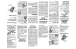
SEAFARER 3 - 4
I NSTALLATION AND OPERATING INSTRUCTIONS
TRANSDUCER INSTALLATION. WARNING:-The co-axial cable is sealed into the stem
of the transducer and if damaged in any way cannot be reconnected. Do not shorten or cut
the transducer lead (nominal length 24 feet or 7.3 metres) or extend it by means of co-axial
plugs or any other method. Any excess cable should be coiled away from excessive heat and
interference from engines or generators. Transducers with longer cable can be supplied to
special order.
For full depth performance the transducer stem should be mounted as near to 90' from the
horizontal as possible. Install the transducer in a part of the hull which is as clear as. possible
from aerated or turbulent water and where accidental damage is unlikely to occur. Normally
a position slightly aft of amidships is preferable.
For fin-keel sailing boats it may be
preferable to fully recess the transducer into the stem so that the face is completely flush.
It should be remembered that the angle of sound wave radiation is 45' and so care should be
taken that a false echo is not created by one of the fin keels. If a single transducer is installed
on the centre line of a boat, depth readings will be obtained up to a heel angle of 22#°. If
two transducers are required, to avoid fin-keels for instance, then each should be fitted in
opposite bilges facing outward at an angle of approximately 15°. By using an automatic
change-over switch, readily available from the manufactures, a twin transducer installation
will enable the Seafarer 3 to give accurate depth readings to heel angle of 37}°.
The following illustration indicates typical transducer installations using a wooden fairing
block outside the hull that has been carefully bored, carved and sanded to a streamline shape
thus avoiding the creation of turbulent water which may reduce or even prevent depth
i ndication when under way. In one of the examples shown, an internal fairing block has been
used for strength, sealing and to allow for hull curvature. The installation should he carefully
rendered watertight by using a sealing compound between all mating surfaces. Do not overtighten the nuts on the transducer stem.
Do Not Shorten
Cable Length
Water Line
Stem Fitting
Not to Scale
.
Bilge Mounting
Transducer Head Embedded in Mastic Sealing Compound
Level Fitting to Avoid
Water Turbulence
"
1 d [lia.
--S mm.
The water exposed face of the transducer may be painted with one thin coat of hard racing
copper, carefully applied so that the paint does not form or trap air bubbles. Take care not
to damage the transducer face or the lead zirconate crystal that it protects. Accidental damage
to this sealed unit cannot be repaired.
Within hull transducer installation.
As an alternative to mounting the transducer with the face in direct contact with water, it
may be mounted within a glassfibre hull. If this method is chosen it must be accepted that
there will be some reduction in the depth reading capability of the instrument, dependant
upon the quality and thickness of the hull.
In the United Kingdom the following parts are readily available from Builders merchants,
Chandlers and model shops. (Alternatively a complete kit of parts, excluding the transducer,
may be obtained from Electronic Laboratories (Marine) Ltd. or from one of their stockists).
Parts required.
Note: It is important that transducer housing tube be made from ABS material and not
Polypropylene or Polythene.
(1) Quantity 1, tube type Z.74 If" 1 /D x Ift. long. (Made by Osma Plastics under the trade
name "Osmaweld").
(2) Quantity 1, socket Z.104 12" I /D. (Made by Osma Plastics under the trade name
"Osmaweld").
(3) Quantity 1, socket plug Z.296 1;" 1/D. (Made by Osma Plastics under the trade name
"Osmaweld").
(4) Quantity 1, tube of polystyrene cement. (As used in the construction of model kits).
(5) Quantity 1, -} pint castor oil.
(6) Quantity 1, medium size glassfibre repair kit (obtainable from garages or chandlers).
Method of installation.
(1) with the boat in 20-30 feet of water, determine a position from inside the hull, ideally
slightly aft of amidships, where the Seafarer gives a reading of the correct depth with the
transducer face pushed hard against the inside of the hull and the gain control turned to
maximum (it will be necessary to wet the face of the transducer with water during this
test to provide a good interface between the transducer and the hull). The transducer
should be as near vertical as possible during this test.
Operate the engine(s) during the test to see that there is no electrical interference, keeping
the co-axial transducer cable away from the engine(s). If minimal or no interference is
recorded by the Seafarer, mark the chosen transducer position inside the hull after making
sure that it is free of water, grease and oil.
(2) Cut the 12" 1/D tube to about 4" long.
Again cut the tube, without decreasing the
overall length of 4", to such an angle that it matches the inside curvature of the hull when
positioned vertically.
(3) Lightly sand the inside surface of part Z.104 and the outside surface of square cut end
of the tube where they will join. Apply a little polystyrene cement to both surfaces and
fix together.
(4) Roughen with sandpaper around the outside of the tube at the end that has been cut to an
angle, approximately 12" up from the base. Place the angled end of the tube into the
chosen position inside the hull.
(5) Carefully mix the glassfibre repair kit to the makers instructions, taking particular note
of the curing temperature requirements. Spread the mix around the base of the tube
where it meets the hull, taking care that none of the mix spreads to the inside of the tube.
Build up the mix to If" around the base of the tube so that the tube will be held
securely in place when the curing process is complete. Keep the tube firmly in position
during the curing process taking care not to "rock" it from side to side, thus making a
potential source of leak when the oil is added.
(6) Drill a 17/32nd" hole in the centre of socket plug (housing cap) Z.296 and a small pilot
hole ;" from the cap periphery to accept a small self-tapping screw.
(7) Remove the top nut from the threaded transducer stem and take it over the plug at the
end of the co-axial cable. Leave the second nut in a position approximately half-way
down the transducer stem. Thread the co-axial plug and lead through the hole in the
housing cap. Push the transducer into the housing that is attached to the hull so that
the transducer face touches the hull. Lightly push the socket cap into position onto the
housing.
(8) Pass the transducer co-axial plug and cable
through the nut previously removed and
TRANSDUCER STEM
thread the nut down the stem until it touch- TRANSDUCER CABLE
es the housing cap (Do not tighten down).
Remove the transducer and cap from the
y"
92 OIA. HOLE
SELF TAPPING SCREW
housing and tighten the inner nut on the
stem up to the inside of the cap, gripping it
,i
securely.
(9) Half fill the housing with the castor oil,
making sure there are no leaks from the
moulding that joins the housing to the
hull. Push the transducer slowly into the
housing, so that the cap fits securely onto
it. Screw in the self-tapping screw into
the pilot hole in the cap,
Push the co-axial transducer plug firmly
into the hack of the instrument.
The
system is now ready for use.
SOCKET PLUG T296
SOCKET 2.104
CEMENT JOINED
CASTOR Bit LEVEL `
SUOACEG
TUBE 2.74-''
GLASSFIBRE
mix
GLASSFIBRE
HULL
==
V WATER
_ = TRANSDUCER FACE
--
-
Notes: (a) By adopting the above method of in hull echo sounding, the pattern of sound
emitted by the transducer remains at approximately 45 ° in a conical shape. If
the transducer and its housing are installed vertically therefore, depth indication
will he given up to a heel angle of 221' (dependant on the thickness of hull
material).
(b) If it is found necessary to take the transducer from the housing, first remove the
self tapping screw to allow air into the housing, thus facilitating withdrawal.
(c) During the season periodically check the oil level in the housing and top up with
castor oil as required. Use of liquids other than castor oil may damage the
transducer for which Electronic Laboratories (Marine) Ltd. will accept no
responsibility.
(d) When under way, a constant stream of aerated water passes across the hull of a
vessel. The thickness of this aerated water generally increases with speed. A
point may therefore be reached when. no ultrasonic sound wave can penetrate the
stream of air bubbles with the result that no depth indications will be received.
INSTRUMENT INSTALLATION. WARNING:-The location of the instrument should be
at least 2 feet (60 cms.) from a magnetic compass.
With the bracket provided the instrument may be mounted in any position through 360°
(The bracket is designed to be slightly undersize to ensure a good grip on the case). This
means it can be facing down from a cabin roof, on top of an instrument panel or console,
or side mounted by the chart table. Bear in mind that it is a sophisticated item of equipment
and should therefore be positioned where it is unlikely to be severely knocked or subjected
to the full force of climatic extremes.
Without using the bracket an alternative method of mounting is to fully recess the instrument
into a panel or bulkhead using the flush mounting flange provided.
Remove the instrument from its case by releasing the four captive screws at the back. Remove
the two side mounting knobs from the case back by undoing the internal fixing nuts. Using
the outer rim of the case back as a pattern or template, cut the appropriate size hole in the
panel or bulkhead. Insert the flush mounting flange between the front and back of the case
making certain the rubber sealing grommet is seated in its channel. (See paragraph on Power
Supply. below). Replace the back of the case and tighten (do not overtighten) the four
captive screws. Pass the back of the case into the hole so that the flange is flush against the
panel. Secure the flange into position with six screws. Connect the transducer lead into the
socket marked "transducer" at the back of the instrument.
8
Key:
I.
Case front.
2.
Case back.
3.
Rubber sealing grommet.
4.
Flange securing screws.
5.
Flush mounting flange.
6.
Bulkhead hole.
7.
Case securing bolts (4).
8.
Side mounting knobs (remove for flush mounting).
5
POWER SUPPLY. The instrument may be powered by either internal batteries or ships
supply of 12, 24 or 32 volts. The back of the instrument must be removed as described
previously in order to connect whatever power source is selected of the two alternatives
given.
Internal batteries. The recommended battery is the Ever Ready PP9 or its international
equivalent (Berec PP9, Ever Ready 276, Mazda RO 618, Diamon EB 39, Pertrix 439,
Superpila 995, Tudor 9T1). Re~~tove the battery clips (on red and black leads) from their
stowage position in the set and clip them onto one of the batteries given above. As an
alternative, two 4.5 volt flat flashlight batteries of the type with two brass contact strips
at the top may be used with an appropriate adaptor.
During the season, periodically check that the battery or batteries show no sign of corrosion
and always remove them at the end of the season. Should the instrument ever need servicing
do not send it through the post with the battery installed.
Internal battery check. Provision has been made to check when the internal battery is
becoming exhausted and should be replaced. The symptoms are as follows:--On the "xl" range, the neon lamp brilliance will become subdued.
At the same depth, the depth shown on the "xl" range will be less than that shown on the
"x6" range. The instrument should then operate only on the "x6" range which will continue
to indicate a true depth until the voltage is insufficient to operate the light emitting diode. As
soon as possible a new battery should be fitted. Batteries can deteriorate in the shop and ideally
should be tested in the following way: Connect the new battery into the instrument in the
usual way and switch on to the "xl" range. A voltmeter connected across the terminals
should then register not less than 9.25 volts.
Ships supply The instrument will accept any ships supply of 12, 24 or 32 volts without
adjustment Damage will be sustained if a higher voltage is connected or if the ships supply
"peaks" in excess of 40 volts.
Remove the back of the case as described previously and make a small hole in the smaller
rubber grommet, marked "External supply" on the case back. Thread the power supply
cables through the rubber grommet and connect the negative supply to the screw terminal
on the set marked - VE and the positive supply to the screw terminal marked +VE. The
internal battery terminals should remain clipped in their transit position when ships supply
If polarity is inadvertently reversed no damage will be sustained but the
is connected.
instrument will not work until the correct polarity is connected. Refit the case together
making sure the rubber sealing grommet around the case is correctly in place.
The current demand is approximately 55 m/a on the "x6" range and 100 m/a on the "xl"
range.
GENERAL OPERvTION. The "xl" range (0-60 feet or 0-18 metres) is for medium or
shallow water work with the "x6" range (0-60 fathoms or 0-108 metres) intended for deep
water echo sounding. On the Seafarer 3 in North America the "xl" range is 0-60 feet and
the "x6" range is 0-60 fathoms, the metric equivalents being omitted. Similarly on the pure
metric version of the Seafarer 3 the "xl" range is 0-20 metres and the "x6" range 0-120 metres.
Switch to one of the two ranges. A light emitting diode will flash at "0" on the dial.
Advance the sensitivity control in a clockwise direction until a second indication
appears. This second indication is the depth of water beneath the face of the transducer. If
the sensitivity control is advanced more than is necessary, multiple echoes of the true depth
with appear. Turn ``e sensitivity control back so that only one echo of sufficient brilliance
is obtained in the interests of both clarity and of battery economy.
To locate fish, advance the sensitivity control beyond that amount normally needed for just
depth indication. Fish will be indicated by random flashes at their appropriate depth,
The efficient performance of all echo sounders depends very greatly upon external factors.
For irstance. a hard, rocky or firm sand sea bed will reflect back ultrasonic sound waves
extremely well The characteristic echo will be shown as a clear thin line of light on the
dial. 0:. the ether hand deep mud or a seabed with a lot of seaweed will give poor reflection
and wi!I adversely affect instrument performance. With practice it is therefore reasonably
easy tc ascertain, no: only the actual depth, but also the type of seabed. Under ideal conditions th.- Seafarer 3 is of ample power to far exceed the 60 fathoms (or 120 metres) marked
on the dig,. this additional depth indication is presented on the dial on a "2nd time round"
basis.
The Seafarer
tc fully guaranteed for twelve months against faults other than those caused by
in
misuse,
the country in which it is purchased. After the guarantee expires, or if problems
arise which are not covered by the terms of guarantee, your instrument will be repaired in
the United Kingdom by the manufacturers or one of their officially authorised main distributors. Unauthorised or inexperienced persons should not attempt to service the instrument
since this is not only likely to worsen whatever fault has arisen but will immediately nullify
the Guarantee. Should it ever he necessary to return the instrument for service, it is essential
the internal battery be removed and that the unit be most carefully packed for transit. A
brief rote (giving your name and address) of the symptoms of failure to operate is of great
assistance to engineers in locating a fault.
TRANSDUCER ANTI-FOULING. One thin coat of hard racing copper anti-fouling paint
should be used. When applied with a soft brush, care should be taken not to trap air bubbles
under the paint. Do not use any other anti-foul paint.
A build-up of barnacles and other marine encrustation on the transducer face will cause
progressive deterioration in instrument maximum depth indicating capability. Barnacles
should be removed by crushjfig between a pair of pliers. Do not tug barnacles off as the
transducer face may become irrepairably damaged. Particles of imbedded shell should be
dissolved away by applying a 20 per cent solution of dilute hydrochloric acid, rinsed off with
fresh water.
TRANSDUCER REPLACEMENT. Additional or spare transducers as well as automatic
change-over switches manufactured by Electronic Laboratories Ltd. are always available,
Fleets Lane, Poole, Dorset
ELECTRONIC LABORATORIES LTD.
Tel. Poole 4641
Telex 41169 Cables Seatronics Poole
I nstruction Part No. 7130