1
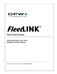
DaaHub
User Guide
&
Installation Manual
Wisper Electric Bicycles
May 2011 - 1st edition
©Copyright 2011 Wisper Ltd
Contents
1
Introduction ..................................................................................................................................... 3
2
First Steps ......................................................................................................................................... 3
3
2.1
Charging the Battery ........................................................................................................ 3
2.2
Tools Required.................................................................................................................. 4
Wheel Installation ............................................................................................................................ 4
3.1
V-brake Version Front Wheel Installation: ....................................................................... 4
3.2
Disc Brake Version Front Wheel Installation:................................................................... 5
3.3
Anti-spin Elbow Installation ............................................................................................. 6
4
Dock Installation ............................................................................................................................... 8
5
Pedal Sensor Installation .................................................................................................................. 8
6
Handle Bar Components Installation ............................................................................................. 11
6.1
Motor Cable and Front Junction Manifold ..................................................................... 11
6.2
Cable Pouch .................................................................................................................... 12
6.3
Brake Sensor................................................................................................................... 13
6.4
Micro-throttle................................................................................................................. 15
6.4.1
6.5
7
8
Throttle installation ................................................................................................. 16
LCD Console .................................................................................................................... 16
Final Steps ...................................................................................................................................... 16
7.1
Performance test:........................................................................................................... 16
7.2
Final Checks .................................................................................................................... 17
Glossary .......................................................................................................................................... 18
2
1
Introduction
Congratulations on purchasing your new DaaHub electric bike conversion kit. This manual
provides you with installation instructions to get you up and running as quickly as possible. It
is recommended that you also check out the DaaHub Installation Video on YouTube. Simply
search ‘DaaHub Installation Video’ or go to…
http://www.youtube.com/watch?v=jWSLemauPgU
If you are familiar with basic bike maintenance, the procedures set out below should be fairly
straightforward. However, if you have any doubt about the installation procedures, or your
level of knowledge, you should consult a qualified bike mechanic at your local shop to assist
with and/or inspect the installation.
2
First Steps
Your DaaHub electric bike conversion kit comes in two separate packages:
1. the DaaHub front wheel motor, inside a wheel bag; and
2. the DaaHub conversion kit components, in a black box.
Open the black DaaHub box and carefully spread the contents out on the floor of your
workspace. The first thing you need to do is get the battery charging while you complete the
installation.
Important: your bike should not be used until the battery is fully charged.
2.1 Charging the Battery
Plug your charger into a power point and turn the power point on at the wall.
Turn the charger switch on. One light will show red (indicating the power is on) and the other
will show green (the charge status light).
Turn your battery upside-down and open the carry handle to
reveal the fuse cap and rubber charger socket cap (see
Figure 1). Pull open the rubber charger socket cap and
carefully insert the charger plug. After a second or two, the
green light will turn to orange, signifying charging has begun.
Note: it is important that the charger is turned on before you
plug it into the battery. This allows the charger to ‘read’ the
battery to determine if charging is necessary. If you plug the
charger into the battery and then turn the charger on,
charging may not commence.
Figure 1
When the battery is fully charged the light will turn green again and the charger fan will stop.
Charging the battery will take about 4-5 hours from fully discharged, less if the battery is only
partially discharged.
3
2.2 Tools Required
Before you start the installation, make sure you have the following tools handy:
an adjustable wrench (8mm-18mm available range), or separate 8mm and 18mm
wrenches;
nippers or strong scissors for cutting tape and clipping flexi-ties;
a set of Allen keys (hex keys); and
a medium Phillips-head screwdriver
Ok, let’s get started.
3
Wheel Installation
Carefully stand your bike upside-down, making sure it is stable and the handlebar components
are not being damaged on the floor.
Remove the front wheel from your bike as per your bike’s user manual. Note: if your bike has
v-brakes or calliper brakes you will have to release them first to remove your wheel (refer to
your bicycle user manual for instructions).
It is a good idea to put your original bicycle wheel into your DaaHub wheel bag for safe storage
after you have removed it.
Hint: you may want to swap your original tyre onto your DaaHub wheel first, if you prefer
matching tyres front and rear.
The instructions for wheel installation vary slightly depending on whether your bike has vbrakes or disc brakes.
3.1 V-brake Version Front Wheel Installation:
Remove the DaaHub front wheel from the wheel bag, loosen
the axle nuts nearly to the end of their travel and carefully
slot the wheel into your front forks. The motor cable should
be on the left side (when the bike is upright) and the motor
cable will be exiting downwards (again, when the bike is
upright).
Remove the rubber nut-cover, the anti-spin elbow (if in
place), the outer washers and the thin final nuts (see
Figure 2) and place them to one side. The standard round
washer (second washer from elbow in Figure 2) will not be
used in the installation.
Figure 2
There are 3 anti-spin adjustment washers on each side of the
motor axle (see Figure 3). Depending on the width of your
forks, position these inside or outside the fork dropouts to fit
the spacing between your fork dropouts. The thicker outside
washer is always placed immediately inside the main axle
nut.
Figure 3
4
For example: if the motor has 1-2mm of free space on each side, position 1-2 anti-spin washers
between the motor and the inside of the dropout on each side. It is good to have a slightly
tight fit, so you have to apply a small amount of pressure to open the forks out to fit the
motor.
Note: with suspension forks it is important you use the adjustment washers to get the correct
fit. If you need to apply too much pressure to open the forks, or the forks pinch together too
much when you tighten the axle nut, this will affect the performance of your forks
Carefully lower your DaaHub wheel into your dropouts, making sure the motor cable is on the
left side (when the bike is upright) and that the motor cable will exit downwards (again, when
the bike is upright).
Tighten your DaaHub axle nuts very firmly (to 65Nm), then reinstall and calibrate your brakes
(refer to your bike’s user manual for instructions).
Important: if you do not have your bicycle user guide and/or are not familiar with bike
maintenance procedures, then have your brakes and other associated wheel components
checked by a qualified bike technician once you have completed your installation. For
example, if you don’t have a torque wrench, or are not familiar with the pressure required
(very firm) for 65nm, you will need to get your bike checked.
Important: recheck and tighten your axle nuts after your first test ride, then again after 1
week, and every 2-3 months after that.
3.2 Disc Brake Version Front Wheel Installation:
Remove the rubber nut-cover, the anti-spin elbow (if in
place), the outer washers and the thin final nuts (see
Figure 4) and place them to one side.
The DaaHub front wheel comes with a 180mm rotor
installed. If your original bike has a 160mm rotor, then you
Figure 4
will need to purchase a 160-180mm adapter from your local
bicycle store. If this is the case, either seek accurate
instructions for installation, or have it installed by a technician (5 minute job).
Carefully lower the DaaHub wheel into your dropouts, making sure the cable will exit
downwards when the bike is upright and the cable will be on the left side (the same side as the
disc brake unit). Ensure that the rotor slots correctly into the
disc brake unit.
There are 3 anti-spin adjustment washers on each side of the
motor axle (see Figure 5). These are used to position the
DaaHub wheel so it aligns with the disc brake unit and fits
the axle width correctly.
For example: if the motor has 1-2mm of free space on each
side, position 1-2 anti-spin washers between the motor and
the inside of the dropout on each side. It is good to have a
5
Figure 5
slightly tight fit, so you have to apply a small amount of pressure to open the forks out to fit
the motor.
Note: with suspension forks it is particularly important you use the adjustment washers to get
the correct fit. If you need to apply too much pressure to open the forks, or the forks pinch
together too much when you tighten the axle nut, this will affect the performance of your
forks
Refer to your bicycle user guide regarding the alignment of the disc callipers. For example, it is
best to have the brake unit centred before installing the DaaHub wheel. This will allow fine
adjustment of the brake unit in either direction once the wheel is installed.
Important: only adjust your brakes if you have your user manual and are competent in bicycle
maintenance. If not, you MUST have the brakes calibrated by a cycle technician to make sure
your bike is safe to ride.
Once you have an approximate alignment, with the suitable number of adjustment washers
inside/outside the dropouts, tighten your axle nuts very firmly (to 65Nm) and check the
alignment of your brakes.
Important: if you don’t have a torque wrench, or are not familiar with the pressure required
(very firm) for 65Nm, get your bike checked by a technician after installation.
Hint: the most common adjustment washer pattern is one washer inside the dropout on the
disc brake side and 3 washers outside on the other side. Try this first.
Important: recheck and tighten your axle nuts after your first test ride, then again after 1
week, and every 2-3 months after that.
Note: If you need to replace your 180mm rotor, the torque settings for the screws are 5nm.
3.3 Anti-spin Elbow Installation
Now we will install the anti-spin elbow onto the right side of
the wheel axle (the opposite side from motor cable), so that
the elbow faces towards the rear of the bike (see Figure 6).
The elbow, special washer, and nut fit on the axle outside
the main axle nut. The main axle nuts should have already
been tightened to the specified torque setting in the
previous step.
Figure 6
Install the anti-spin elbow (elbow to rear of bike), then place the thin anti-spin washer onto
the axle over the elbow and finally twist on the thin axle nut.
Note: in the original DaaHub YouTube installation video, the washer is shown being placed
between the elbow and main axle nut. We have revised the installation to the above method
i.e. the anti-spin washer should be placed between the anti-spin elbow and the outer (final)
thin axle nut.
Tighten the nut to firm finger-tightness (it will be fully tightened in a later step). You want the
elbow firm, so it cannot wobble left to right, but can still rotate slightly on the axle, without
too much pressure needed.
6
Retrieve the anti-spin arm clamp and adjustable arm (see
Figure 7).
Remove the adjustable arm from the clamp. Wind the arm
out (turn the middle bar) until the arm is approximately in
the middle of its adjustment range (about 1cm of exposed
thread at each end). Make sure the thread is evenly exposed
at either end of the middle bar.
Open the clamp by turning the clamp adjustment tab
Figure 7
anticlockwise until it fully unscrews and you can open out
the clamp ring. Carefully place the clamp ring around your right fork (opposite side from
motor cable), temporarily aligning the adjustable arm against the end of the anti-spin elbow to
estimate the appropriate clamp height.
Tighten the clamp by turning the adjustment tab clockwise. Be careful with the first turn as
the clamp ring screw needs to grip back into the adjustment thread to begin tightening the
clamp. Tighten the clamp to firm finger tightness, so it locks tightly onto your fork
Hint: you may want to use a piece of the supplied DaaTape to cover your forks under the
clamp to avoid scratching.
You are aiming to get the mount points at either end of the adjustable arm aligned with the
holes on the end of the elbow and the clamp ring tab respectively (something like Figure 6). In
addition, you want to avoid the adjustable arm contacting the fork (more of a potential
problem with large diameter forks). To get the best ‘fit’, you will need to adjust the position
and angle of the clamp ring, possibly reversing the direction it is mounted. Try attaching the
adjust arm to the anti-spin elbow while you are finalising the alignment. Once you are happy
with the general position and alignment, use a small Allen key to tighten the adjustment tab
on the clamp ring half a turn so the clamp is tight. Generally the best fit for the adjustable arm
at the other end will be on the final hole at the end of the anti-spin elbow.
Important: do not over-tighten the clamp as it may break! It only needs to be tightened slightly
past firm finger tightness.
Install the adjustable arm onto the clamp by inserting the supplied screw through the clamp
adjustment tab centre hole and then the end hole of the adjustable arm, then tighten the lock
nut until the arm can still turn with light pressure, but does not wobble.
Align the other end of the adjustable arm with the appropriate (best aligned) end hole on the
anti-spin elbow (if not already in place). Adjust the length of the arm to line up the holes and
then attach the arm to the elbow with the supplied screw and locknut. Tighten the nut just
enough so there is no wobble.
Turn the middle piece of the adjustable arm with your fingers (shortening the arm) until the
anti-spin elbow is just pulled around tight. Then use a small Allen key to give the adjustment
bar another half turn.
Important: do not over-tighten your adjustment arm as you could damage your forks and
make your bike unsafe to ride.
Tighten the outer thin nut firmly (to 40 Nm).
Your DaaHub front wheel is now installed.
7
Dock Installation
With the bike still upside-down we will now install the main
dock. Depending on your frame style and personal
preference you can either mount it inside the frame (in most
standard diamond frame hard-tail bikes) or behind the seat
post (see figures 8 and 9). The seat post option is the most
widely compatible option.
Remove the dock from your component box along with the
three pairs of rubber sleeves. Choose the appropriate
diameter sleeve for your frame / seat post tube diameter to
ensure a snug fit when tightened.
Figure 8
Using the special Allen key supplied, remove the four screws
for the dock to release the clamp. This special head pattern
is a security feature to prevent the dock from being easily
removed by a third party (make sure you store it in a safe
place you will need it if you ever want to remove the dock).
Insert the selected sleeve into the dock clamp and install the
dock onto the appropriate part of your bike and re-install the
four screws.
Figure 9
Hint: The two male battery terminals should be to the top of
the dock. Make sure you leave enough room above the dock for the battery.
Note: If mounting within the frame, some bikes may have the front derailleur cable in the
same area. It is ok to mount under this, even if the cable has to stretch to go over the clamp.
You will just need to readjust your cable tension after installation is complete. If the cable fit is
very tight, you may want to file a small cable guide into the edges of the clamp to help it and
avoid cable damage.
Only fasten the screws slightly at this stage so the dock will not wobble, but can still easily be
rotated left to right. Also ensure that the screws are tightened evenly so the gap between the
clamp and dock is fairly similar for each screw.
4
Pedal Sensor Installation
The DaaHub kit uses a pedal cadence sensor to sense when
you are pedalling and trigger the motor for Pedal Assist
Mode (6 levels available from your console).
The kit comes with two sensor mount options to maximize
compatibility with all bikes:
1. Rear horizontal mount.
This mount simply fastens around your rear left horizontal
fork (close to the bottom bracket) with a flexi-tie and is the
most common mount used (Figure 10).
8
Figure 10
2. Bottom bracket mount.
This mount is fastened to the underside of your bottom
bracket using the double-sided adhesive and DaaTape
supplied (Figure 11).
The sensor mount has two holes at one end so the sensor
can be fastened to it at two different heights to allow for
varying bottom bracket diameters. Choose the position that
matches the sensor best with the magnet diameter.
Figure 11
Choosing the Appropriate Mount
One mount will be attached to the dock cable and the other will be attached to the spare
pedal sensor/cable. Retrieve both the mounts/sensors and the DaaHub 2-piece magnet disc.
Note: the dock comes with about 300mm of pedal sensor cable exiting the dock. There is
another 300mm available inside the dock. The amount of cable you will require will depend on
the size/style of your frame and your mounting position. If you need more cable to get the
sensor down to your axle area, lightly pull the cable to draw more cable out.
Clip the 2-piece magnet disc onto your left (when bike
upright) side axle, between the pedal and bottom bracket,
with the Wisper logo outwards. The 2-piece disc avoids the
need to remove your crank to install the disc. If the disc is a
slightly loose fit, you may use flexi-ties around the crank
outside the disc to prevent horizontal movement (see Figure
12). In most cases this won’t be required.
Note: If you have a hollow crank axle, you can break out or
Figure 12
trim the inner fins on the disc for the bigger diameter. You
can then use a small file to better shape the disc to fit around your left crank if need be.
Hint: as an alternative, you can also glue the disc to the inside of your inner chain ring on the
right side and install the bottom bracket sensor to match. Be sure to check your disc is the
correct way before permanently fastening it. To test this, wait until your kit is fully installed
and battery charged, the test it in assist mode level 1. If pedal assist mode triggers only when
you pedal backwards, then flip your disc over before gluing!
Using the above pictures and description as a reference, temporarily place both sensor mounts
in their designated positions and decide which is the most suitable for your bike.
Note: the sensor should be approximately 2mm from the magnets in the disc.
Once you have decided the best mount follow the specific instruction below.
9
1. Rear horizontal mount.
Use one of the supplied small-sized flexi-ties to insert
through the mount holes on the sensor plate, then fasten
the sensor to the appropriate part of your rear horizontal so
it is aligned with the disc and pointing the same direction as
in the pictures.
Hint: if you think of the sensor as an arrowhead (cable
behind it), then it points in the opposite direction of
rotation when the pedals are moving the bike forwards.
Figure 13
Hint: On some frames, where the weld of the kickstand
mount to the horizontal is close, this ‘bump’ may force the flexi-tie to creep forward on the
horizontal, so you may want to install a second flexi-tie looping through the first, then back
along the horizontal and thru the kickstand mount. Apply the correct tension, so this second
tie pulls the sensor mount back along the horizontal and hence back in line with the magnets.
Bike frames vary considerably, and some will take a little more trial and error to get the mount
point right than others. You can also use DaaTape to bind the sensor in place on the horizontal
if need be. It can still sensor the magnet disc through a few layers of tape.
Hint: later, when you test the system and all is okay, you can use more flex ties, or DaaTape to
tidy the sensor cable against the seat-post tube frame.
2. Bottom bracket mount.
Decide the suitable position on the bottom bracket to fasten
the mount (normally on the underside).
Hint: the mount is semi flexible so you can bend it to get the
best fit to the curve of your bottom bracket.
Clean the bottom bracket with a damp cloth, and then polish
dry with tissue.
Cut a suitable sized piece of the double-sided adhesive to
Figure 14
fasten both mounting ‘feet’ then the peel the backing paper
and smooth the tape onto the appropriate part of the
bottom bracket (see Figure 14). Carefully peel the topside paper. Carefully set the mount
onto the adhesive strip.
Check your 2mm gap to the magnet disc then remove the disc to make the next steps easier.
Cut another strip of double sided tape and repeat the above
process to lay it over the mount feet.
Then cut a 250mm length of DaaTape, peel the backing
paper and carefully wrap it over the mount and around the
bottom bracket (fully cleaned by now!), keeping good
tension, and being careful to keep it on the bottom bracket
and not let it slip over the edge. Wrap it around again and
back over itself.
Finally, smooth the tape down to make sure it is properly
stuck.
10
Figure 15
Note: DaaTape is of a very high quality, and is semi flexible to allow for the irregular bind
sometimes needed to fasten the mount properly. It is ok to curve it up over the curve of welds,
etc. Key points are that your surface is clean and you keep a good tension as you wind it.
Hint: keeping the tape tight and continuing to ‘pull ahead’ as you wrap it around makes for a
stronger application.
5
Handle Bar Components Installation
Carefully turn your bike upright again and lean it against a wall or lower the stand if it has one.
Unfold the motor cable and main component cable from the underside of the dock and
remove any twists.
5.1 Motor Cable and Front Junction Manifold
Plug the motor cable into the motor, making sure that the
arrows on both plugs align so that the pins are in the correct
position when you insert the plug. (figure 16) Once you are
sure the arrows and pins are aligned properly, the plug should
be pushed firmly in, up to the marker line.
Important: should you need to unplug the motor cable to fix a
puncture, you must be very careful when plugging it in again
that the arrows line up, otherwise you could seriously damage
the plug.
Figure 16
The motor cable should be exiting downwards and to the rear
of the bike, as per earlier instructions. Use DaaTape or a flexi-tie
to fasten it to your fork. Use the double-cable clip to parallelattach the motor cable to one of the bike cables above the forks,
e.g. the front brake cable (see Figure 17). You will have excess
motor cable between the forks and the dock which will be tidied
away in a later step.
Run the main cable from the dock up to your handlebar and
decide the position you want to install the front junction
manifold.
11
Figure 17
Note: the most common positions are under the centre of the handle bar (Figure 18), or to the
side of the head tube (Figure 19). The first option is best, as the cables move with the
handlebars.
Figure 18
Figure 19
Once you have decided your front junction manifold mounting position, bend the semi flexible
mount on the back of the junction box to the appropriate angle. Next, cut a suitable length of
double-sided tape and fasten it to the frame/headset stem where the junction mount plate
will go. Make sure you clean the frame surface before applying the tape. Peel off the surface
paper then carefully apply the mount onto the adhesive.
Cut a suitable length of DaaTape and bind the mount firmly to the frame (Figure 18).
Note: there is also a 1 1/8 head tube-mounting component.
(Figure 20) To use this option, remove the existing mount
from your front junction manifold and install the 1 1/8 head
tube mount.
Next remove the headset and desired number of spacer rings
(refer to your bicycle user manual), install the mount and
then reinstall your headset and handlebars as per your user
guide.
Figure 20
5.2 Cable Pouch
Now we need to tidy away the excess motor and main cable
between the dock and front of the bike. Retrieve the cable
pouch and install it on a suitable part of your frame with the
Velcro straps, then carefully fold the excess cable into it and
fasten the Velcro edges and strapping (Figure 21). Make sure
you install the pouch inside any brake/gear cables.
12
Figure 21
5.3 Brake Sensor
The magnetic brake sensors are applied to your existing
brake levers so that the system can register when the brakes
are applied. Retrieve the brake sensors, DaaCube mounts
and magnets.
The magnet is the separate cylinder shown in Figure 22
Figure 22
inserted into a DaaCube. The flat end (non-concave) of the
cylinder has the magnet. The DaaCube is a rubber mount that allows the height and angle of
the magnet (or sensor) to be changed. The sensor (shown on the left in Figure 22) is attached
to a cable, which connects to the front cable manifold.
The sensor and magnet need to be placed along the line of the main brake lever, so they meet
where the lever butts against the main body of the brake unit and the end of the sensor and
the magnet just touch when the brake is not in use. Then when the brake is applied, a gap is
created between the sensor and the magnet and the safety cut-off feature is triggered.
There are two options for mounting the brake sensors to your levers.
1. DaaTape
The first and simplest option is to use the double-sided adhesive and DaaTape. This is the best
option for most bikes.
2. DaaCube
On bike with minimal lever movement (high- end hydraulics, etc.) or large height differential
between lever mount point and sensor mount point you may need to use one or both
DaaCubes per installation. The DaaCubes are used to raise the height of the sensor or magnet
to get good alignment with the opposite magnet/sensor. DaaCubes also remain easily
adjustable after application for fine-tuning the sensor gap.
Note: On some bikes it may be best to use both options (see
figure 23). In this bike we used DaaCube installation for the
lever side (to minimize lever space taken and allow an
‘overhang’ of the magnet onto the main body where the
sensor is mounted and we used DaaTape installation on the
sensor side (also with one of the wedges (see below
instructions) fixed underneath the sensor with double-sided
tape to get the required alignment).
Figure 23
DaaTape installation option:
Hint: We recommend applying the sensor / magnet to the
underside of your brake lever so it is out of sight. If you wish
to do so, carefully turn your bike upside-down, making sure
that you do not damage any of the handlebar components
on the floor.
13
Figure 23
Choose the position of the sensor and magnet, with the sensor on the main part of the brake
lever and the magnet on the lever arm.
Remember the spot and apply double sided tape to both sides of the lever (the sensor and the
magnet positions) then lightly stick the sensor and magnet to the tape. Apply the brakes and
check there is a zero to 1mm gap when the brakes are not in use and a 5mm+ gap when the
brakes are fully engaged.
Once you are happy with the positioning, cut suitable lengths of DaaTape and fasten the
sensors. Use two parallel strips on the sensor and magnet.
Hint: if you are unsure your gap is correct you may choose to leave the final DaaTape
application until your battery is charged and you can performance test before permanently
applying the units.
Plug the sensor into the main cable via the front junction manifold and the appropriate twopin receptor. Be careful to align the plug correctly to the socket as you plug it in.
Repeat process for the other side brake
DaaCube Installation Option
Carefully remove your DaaCubes and the small wedges from their bag. Place the wedges
somewhere they will not get lost.
The DaaCube has a cone-shaped tunnel thru it, so you can
place a wedge above, or below, the magnet/sensor, to alter
its angle up or down. Also, depending from which side you
insert the magnet/sensor, you will get different amounts of
height adjustment. (Figure 25)
Insert magnet and sensor into the DaaCubes then position
them on your brakes and adjust the angles, insertion
direction, etc., until you get a good proximity of sensor and
magnet.
Figure 25
Insert the wedges and push in further with a small Allen key
to lock the magnets/sensors in position.
Next loop two small flexi-ties though the base slots in the DaaCubes (but keep them open),
then reposition the cubes and sensors/magnets on the designated spots on the brake lever.
Carefully loop one of the flexi-ties around and through its zip lock and pull it so it is lightly
tight. Do the same for the other, then alternated tightening each one until you have a firm
final hold.
Repeat the process for the other cube.
Fine-tune the magnet/sensor gap so it is 0-1mm when the brake is not in use and 5mm+ when
brake is in use.
Note: if you prefer, you can also further bind the DaaCube with DaaTape.
Note: as mentioned earlier, it may suit your bike best to use DaaCube on the magnet side
(lever side) and DaaTape on the sensor side.
14
5.4 Micro-throttle
The micro-throttle is best installed on the right side of the
handlebars; with the LCD console the left side.
The preferred position of the micro-throttle is over the right
brake lever mount ring, adjacent to the right hand grip.
The micro-throttle has adjustable aluminium mount plates that can be bent and also faced
inwards or outwards and slide-adjusted (the screw fastening
holes on the mount plates are oval) to ensure the best fit
Figure 26
(see Figure 27).
The mount plates have 3 mounting holes, two of which you
thread the cable-ties though to attach the unit to the bike.
Note: brake mount rings vary in shape considerably. However,
with a little patience, you will get a good fit on all styles.
Position the micro-throttle over your right brake lever
handlebar mount.
Observe how the micro-throttle sits onto the curve of the
handlebar and rotate and or bend the micro throttle mounts
until you get a good fit.
Figure 27
Next insert two small flexi-ties through the outer holes of both mounts (so each flexi-tie will
pass through both mounts, one on the left side of the throttle, one on the right side) then
reposition the micro-throttle onto the appropriate position on the brake lever mount ring on
the handlebar. Loop the ties around the handlebar (one on each side of the brake lever mount
ring) and back through the zip locks. Lightly tighten each tie, alternately applying more tension
to each, until the micro throttle has the correct alignment and will not slip when you operate
the buttons.
Hint: if you find it difficult to get the throttle firm enough not to slip, remove the unit (cut your
flexi-ties), then apply a suitably placed piece of double sided adhesive tape and then reapply
two more cable-ties.
Hint: you can also use DaaTape to bind around the edge of the micro throttle, then around the
handlebar.
Clip the ends off the flexi-ties, then plug the micro-throttle into the appropriate plug in the
main cable, being careful the plug and socket align correctly before you insert them.
Note: you can use one of the supplied cable links to attach the micro throttle cable neatly to
the brake cable, or can use a little DaaTape if you prefer.
15
5.4.1
Throttle installation
DaaHub also comes with a standard throttle. If you prefer
you can install this instead of the micro throttle, but a
throttle is less compatible with gear shifters, and can get in
the way of smooth gear operation.
Note: even though it may take a little bit of getting used to
initially, the micro-throttle is the best option for
compatibility, simplicity and ease of use.
Figure 28
Note: you will find you will mostly use the 6 levels of Pedal Assist anyway, just using the
throttle when you need instant extra boost.
To install the standard throttle, remove the left hand grip and slide the throttle on, then
tighten the hex screw. Slide the plastic ring on, then the handgrip end piece.
Hint: to free up your gear shifters, you can also install the throttle on the outside end of your
right handgrip. However, for this type of installation, the cable is more vulnerable (as it is now
on the outside) and you have to bind it along the inside of your brake lever to keep it out of
the way. You also need to cut a short section of your original handgrip to insert inside the
throttle to give you a full handgrip.
5.5 LCD Console
Install the LCD console on the left side of your handlebar.
Simply unscrew the bracket screw to open the bracket, and
slide the unit as close to the left hand grip as possible before
tightening the screw.
Note: on larger diameter handlebars you will have to push
firmly while you turn the screw to get it to thread in, or you
may even need a longer compatible screw (but don’t get one
too long otherwise you may damage the LCD when you
tighten it)
Figure 29
Plug the cable into the matching five-pin plug on the front
junction manifold, being careful the plug and socket line up in the correct fashion before
inserting.
Tidy any loose cable as necessary, using cable links or DaaTape.
6
Final Steps
Wait for your battery to fully charge then install it onto your bike and performance test all your
components.
6.1
Performance test:
1. Make sure the battery key is turned fully anticlockwise to the ‘open’ position (push it
to turn it if it is locked in the ‘off’ position). Once you are in the ‘open’ position,
slide the battery fully onto the dock (its front edge will be touching the dock edge
16
2.
3.
4.
5.
6.
when it is fully engaged), then turn the key fully clockwise until it is in the ‘on’
position (horizontal).
Press the power on button on your LCD console and the screen should boot up,
temporarily showing the wheel diameter (you can change the wheel diameter by
holding the set button for 10 seconds, then use up / down buttons)
Mount your bike (you must be outside, in a ride-able area, for these next steps).
Use the up button to change the PA level to 1 bar. Carefully ride away and after about
one pedal turn you should feel the assist power begin. Lift to level 2, 3, etc. to get
more power. If assist does not happen then test the throttle (as below). If throttle
works (but pedal assist does not), then it will be your pedal sensor that needs
checking. Return to the relevant installation instructions and recheck you gap is
correct etc. If both the throttle and the pedal assist function do not work, then
recheck your brake sensors, as one of the gaps is probably too big and the safety
feature has cut the motor off.
Brake sensors. While you are in assist mode, apply your left brake and the motor
should cutout. Repeat the process for your right brake. If the motor does not
cutout, return to your sensor instructions. Either your sensor is not fully plugged
in, or the gap when brakes are engaged is less than 5mm.
Micro Throttle. Once the brakes have been tested and perform ok, you can test the
micro throttle. With pedal assist to level 1 (on level 0 the throttle will not operate)
push and hold the button with the smallest dot for low boost; push the middle
button for moderate boost; and push the end button for maximum power. You can
lock on the throttle by double clicking. As soon as you touch the brakes, or one of
the other 2 buttons, the lock-on function will be cancelled.
6.2 Final Checks
Once the component tests have been completed successfully, permanently install any semiinstalled components and tighten your main dock.
Check over each individual component you have installed and ensure that all screws and nuts
are tightened to the specified torque settings.
Check that all excess or loose cables have been tidied and secured.
Check all cable-tie and adhesive mountings to ensure they are secure.
Hint: on small framed bikes, where you are installing within the frame you can leave the dock
mount screws a little loose so, to remove/install the battery you simply swivel the dock out of
the frame a little.
Now you are ready to go!
We hope you enjoy your DaaHub electric bike conversion kit!
17
7
Glossary
A glossary of electric bike specific terms is included below to assist with providing standardised
descriptions of components.
This terminology is also used in the relevant sections of this manual where further information
will be found regarding these components and their function.
Standard (non-electric) bicycle terms are not included.
Standard throttle – a twist grip device fitted to the handlebars to activate the electric motor.
Micro-throttle – a 3 button-style throttle specifically designed for DaaHub. Low, medium or
high throttle settings may be engaged by holding a button down. Double-clicking sets the
throttle and engaging a brake lever re-sets the throttle to zero.
LCD display - a type of display fitted to the handlebars incorporating a liquid crystal display
(LCD) providing information to the rider relating to the operating mode of the bike and
diagnostic information. Also provides switch functions.
Brake cut out switch – a red sensor magnetic switch incorporated in each brake lever
operation to cut the power to the motor when the brakes are applied.
Front junction manifold – a junction where components such as the LCD display and brake
sensors are plugged into. The main wire leads back to the controller from the manifold.
DaaTape – purpose-designed tape for mounting components of the DaaHub kit;
DaaCube – purpose-designed brake sensor unit for small-travel brake levers;
Main wiring loom – a single multicore cable running from the front junction manifold back to
the bike controller.
Hub Motor – the main electric motor fitted to either the front wheel
Sensor-less motor - a highly efficient and reliable type of brushless motor, which does not
incorporate movement sensors to control the power applied to the motor e.g. the DaaHub
motor.
Brushless motor- All Wisper and DaaHub motors are brushless, as they do not use carbon
brushes to provide power to the motor. Brushes are prone to wear causing possible reliability
problems and hence are not used in Wisper motors.
Pedal sensor – a sensor fitted to the bottom bracket of the bike to detect rotation of the pedal
cranks.
Controller – an electronic control unit housed inside the DaaHub dock, which takes inputs
from all of the above control devices and provides a regulated output to the motor.
Hall Effect – a type of magnetically operated movement sensor used in the throttles, brake cut
out switch and pedal sensors.
Battery – the main battery fitted to the bike to provide power to the electric motor.
Advanced Lithium (polymer) – describes the type of battery material /chemistry and
associated construction used by Wisper.
18