1
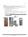
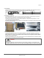
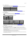
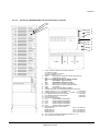
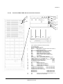
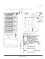
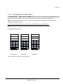
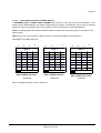
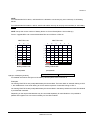
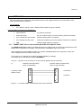
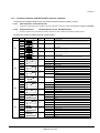
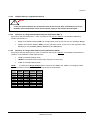
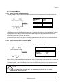
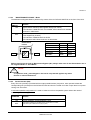
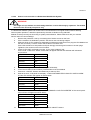
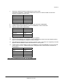
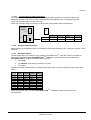
Section-4
4.1.2.4
ON/OFF Start-up and Shutdown Buttons
.
!
NOTE!
in the case that the parallel ups system has to be turned off, then both on/off buttons on all ups
modules have to be pushed. in this case the power supply to the load will be interrupted
4.1.2.5
Definition of a Single/Parallel-Module System (DIP Switch SW1-1)
By means of the DIP Switch SW1-1, which is located on the front of a Module, it is possible to determine
whether the Module is a:
4.1.2.6
•
Single UPS (Switch Position LOW). On the right hand corner of the LCD you can read S (for Single)
•
Parallel UPS (Switch Position HIGH). On the right hand corner of the LCD of the respective UPSModules you can read P01 (Master), P02 (slave) and P03 (Slave)
Definition of a Single/ Multi-Cabinet Chain (DIP Switch SW1-9)
By means of the DIP Switch SW1-9, which is located on the front of a Cabinet, it is possible to determine the
“position” of the Cabinets in Multi-Cabinet Chain:
•
“First” in the Multi-Cabinet Chain
•
“Middle” in the Multi-Cabinet Chain (there may be more than one)
•
“Last” in the Multi-Cabinet Chain.
If a Cabinet is a Single Cabinet then it is seen as the “First” and “Last” in an imaginary Chain.
NOTE:
So the positions of the DIP Switch SW1-9 must be set as shown below:
SW1-9
1
2
3
4
5
6
7
8
9
Single
Cabinet
ON
ON
ON
ON
ON
ON
ON
ON
ON
First
Cabinet
ON
ON
ON
ON
ON
ON
ON
ON
OFF
Middle
Cabinet
OFF
OFF
OFF
OFF
OFF
OFF
OFF
OFF
OFF
Last
Cabinet
ON
ON
ON
ON
ON
ON
ON
OFF
ON
NRG VALUENET DPA USER MANUAL
Page 4/9
Modifications reserved