1
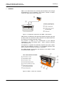
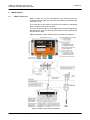
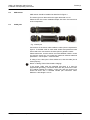
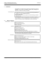
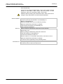
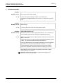
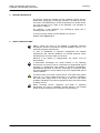
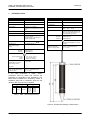
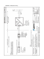
Labkotec Oy
Myllyhaantie 6
FI-33960 PIRKKALA
FINLAND
Tel: +358 29 006 260
Fax: +358 29 006 1260
Internet: www.labkotec.com
16.3.2012
D15530_e
1/12
OMS-1
Oil Separator Alarm Device
Installation and Operating Instructions
Copyright © 2012 Labkotec Oy
We reserve the right for changes without notice
OMS-1 Oil Separator Alarm Device
Installation and Operating Instructions
D15530_e
TABLE OF CONTENTS
1 GENERAL ............................................................................................................ 3 2 INSTALLATION ................................................................................................... 4 2.1 OMS-1 control unit ....................................................................................... 4 2.2 OMS sensor ................................................................................................. 5 2.3 Cable joint .................................................................................................... 5 3 OPERATION ........................................................................................................ 6 3.1 Modes of operation ...................................................................................... 6 4 TROUBLE-SHOOTING ....................................................................................... 8 5 REPAIR AND SERVICE ...................................................................................... 9 6 SAFETY INSTRUCTIONS ................................................................................... 9 7 TECHNICAL DATA ............................................................................................ 10 APPENDIX 1. OMS SYSTEM DRAWING .............................................................. 11 SYMBOLS
Warning / Attention
Pay special attention to installations at explosive atmospheres
Device is protected by double or reinforced insulation
Copyright © 2012 Labkotec Oy
2/12
We reserve the right for changes without notice
OMS-1 Oil Separator Alarm Device
Installation and Operating Instructions
1
D15530_e
GENERAL
OMS-1 is an alarm device for monitoring the thickness of the oil layer
accumulating in an oil separator. The system consists of OMS-1
control unit, OMS sensor and a cable joint.
Figure 1. Oil separator supervision with OMS-1 alarm device
OMS sensor is installed into the light liquid storage chamber and gives
an alarm when the chamber oil layer reaches a pre-determined level.
The sensor is normally immersed in water.
The function is based on the measurement of the electrical
conductivity of the surrounding liquid – water conducts electricity
much better than oil.
Oil separator is regarded as potentially explosive (Ex) area. OMS-1
sensor can be installed in a zone 0, 1 or 2 potentially explosive area
but the control unit must be mounted in a safe area.
The LED indicators, push button and interfaces of the OMS-1 control
unit are described in figure 2.
Figure 2. OMS-1 control unit - features
Copyright © 2012 Labkotec Oy
3/12
We reserve the right for changes without notice
OMS-1 Oil Separator Alarm Device
Installation and Operating Instructions
2
2.1
D15530_e
INSTALLATION
OMS-1 control unit
OMS-1 control unit can be wall-mounted. The mounting holes are
located in the base plate of the enclosure, beneath the mounting holes
of the front cover.
The connectors of the external conductors are isolated by separating
plate. The plate must not be removed.
The cover of the enclosure must be tightened so, that the edges touch
the base frame. Only then does the push button function properly and
the enclosure is tight.
Before installation, please read the safety instructions in chapter 6!
Figure 3. OMS-1 alarm device installation.
Copyright © 2012 Labkotec Oy
4/12
We reserve the right for changes without notice
OMS-1 Oil Separator Alarm Device
Installation and Operating Instructions
2.2
D15530_e
OMS sensor
OMS sensor should be installed as described in figure 3.
The sensor gives an alarm when the upper electrode is in oil.
Please check the correct installation depth also from the instructions
of the oil separator.
2.3
Cable joint
Fig. 4 Cable joint
Connections of the sensor cable inside the cable joint are explained in
figure 3. If shielded cable is used cable shields and possible excess
wires need to be connected to the same point in galvanic contact.
Please make sure, that the sensor and cable between OMS-1 control
unit and the sensor do not exceed the maximum allowed electrical
parameters – see chapter 7 Technical data.
IP rating of the cable joint is IP68. Make sure, that the cable joint is
closed properly.
Notice in cabling: Risk of electrostatic charging!
If the sensor cable must be extended and there is a need for
equipotential grounding, it should be done with the junction box LJB2.
The cabling between the OMS-1 control unit and the junction box
should be done with a shielded twisted pair instrument cable.
Maximum cable length is 100 m.
Copyright © 2012 Labkotec Oy
5/12
We reserve the right for changes without notice
OMS-1 Oil Separator Alarm Device
Installation and Operating Instructions
3
D15530_e
OPERATION
The operation of the alarm device should be checked always after the
installation. Also check the operation always when emptying the
separator or at least once every six months.
Functionality test
1. Immerse the sensor into water. The device should be in normal mode.
2. Lift the sensor up in air or oil. An Oil alarm should be generated (see
chapter 3.1 for more detailed description).
3. Clean up the sensor.
4. Immerse the sensor back into water. The alarm should go off after a
delay of 10 sec.
A more detailed description of the operation is provided in chapter 3.1.
If the operation is not as described here, check connections and
cabling. If necessary contact a representative of the manufacturer.
3.1
Modes of operation
Normal mode – no alarms
Oil alarm
Sensor is totally immersed in water.
Mains LED indicator is on.
Other LED indicators are off.
Relay is energized.
Sensor is immersed in oil. (the sensor gives an alarm when the upper
electrode is in oil).
Mains LED indicator is on.
Oil Alarm LED indicator is on.
Buzzer on after 10 sec delay.
Relay de-energize after 10 sec delay.
(Note. The same alarm takes place when OMS sensor is in the air.)
After removal of an alarm, the Oil Alarm LED indicator and buzzer will be
off, and relay will be energized after 10 sec delay.
Fault alarm
Reset of an alarm
Copyright © 2012 Labkotec Oy
Sensor cable break, short circuit or a broken sensor.
Mains LED indicator is on.
Sensor circuit Fault LED indicator is on after 10 sec delay.
Buzzer is on after 10 sec delay.
The relay de-energize after 10 sec delay.
When pressing the Reset/Test push button.
Buzzer will go off.
If the buzzer is not reset, it goes off automatically after three days.
6/12
We reserve the right for changes without notice
OMS-1 Oil Separator Alarm Device
Installation and Operating Instructions
D15530_e
TEST FUNCTION
Test function provides an artificial alarm, which can be used to test the
function of the OMS-1 alarm device and the function of other
equipment, which are connected to OMS-1 via its relay.
Attention! Before pressing the Reset/Test button, make sure that the
change of relay status does not cause hazards elsewhere!
Normal situation
When pressing the Reset/Test push button:
Oil Alarm and Fault LED indicators are immediately on.
Buzzer is immediately on.
Relay de-energize after 2 sec of continuous pressing.
When the Reset/Test push button is released:
LED indicators and buzzer go immediately off.
Relay energize immediately.
Alarm on
When pressing the Reset/Test push button for the first time:
Buzzer will go off.
When pressing the Reset/Test push button after that:
Fault LED indicator is immediately on.
Oil Alarm LED indicator remains on.
Buzzer remains on. If it has been reset earlier, it will return to be on.
When the Reset/Test push button is released:
The device returns right away to the preceding status.
Fault alarm on
Copyright © 2012 Labkotec Oy
When pressing the Reset/Test push button:
The device does not react to the test at all.
7/12
We reserve the right for changes without notice
OMS-1 Oil Separator Alarm Device
Installation and Operating Instructions
4
D15530_e
TROUBLE-SHOOTING
Problem:
Possible reason:
To do:
MAINS LED indicator is off
Device doesn’t get supply voltage.
1. Check that power separation switch is not switched off.
2. Measure the voltage between poles N and L1. It should be 230 VAC +
10 %.
Problem:
Possible reason:
To do:
Problem:
No alarm when sensor in oil or air, or the alarm will not go off
Sensor is dirty.
1. Clean-up the sensor and check the operation again.
FAULT LED indicator is on
Possible reason:
Resistance in sensor circuit too high (cable break or out of connector) or
too low (cable in short circuit). The sensor might also be broken.
To do:
1. Make sure, that the sensor cable has been connected correctly to the
OMS-1 control unit.
2. Disconnect sensor’s [+] wire and measure resistance between [+] and
[-] wires. The measured resistance should be 46-48 kΩ.
3. If it is possible measure also resistance between [+] wire and sensor’s
upper electrode. The measured resistance should be 1,1 – 1,3 kΩ.
4. If the resistance values in items 2 and 3 are correct, then OMS-1
control unit is defective, otherwise problem is in cabling or in sensor.
If the problem can not be solved with the above instructions, please
contact Labkotec Oy’s service.
Attention! If the sensor is located in an explosive atmosphere, the
multimeter must be Exi-approved!
Copyright © 2012 Labkotec Oy
8/12
We reserve the right for changes without notice
OMS-1 Oil Separator Alarm Device
Installation and Operating Instructions
5
D15530_e
REPAIR AND SERVICE
The sensor should be cleaned and the operation should also be
tested when emptying the oil storage chamber or at least once every
six months. The easiest way to check the operation is to lift the sensor
up in the air and to put it back to the separator. The operation is
described in chapter 3.
For cleaning, a mild detergent (e.g. washing-up liquid) and a
scrubbing brush can be used.
In case of queries, please contact Labkotec Oy’s service:
[email protected].
6
SAFETY INSTRUCTIONS
OMS-1 control unit must not be installed in potentially explosive
atmosphere. Sensors connected to it may be installed in zone 0, 1 or 2
potentially explosive atmospheres.
In case of installations in explosive atmospheres the national
requirements and relevant standards as IEC/EN 60079-25 and/or
IEC/EN 60079-14 must be taken into account.
Warning! If the cabling is voltage-tested, the sensor must be
disconnected.
If electrostatic discharges can cause hazards in the operating
environment, the device must be connected into equipotential ground
according to requirements with regards to explosive atmospheres.
Equipotential grounding is made by connecting all conductive parts
into same potential e.g. at the cable junction box. Equipotential ground
must be earthed.
The device does not include a mains switch. A two pole mains switch
(250 VAC 1 A), which isolates both lines (L1, N) must be installed in
the main power supply lines in the vicinity of the unit. This switch
facilitates maintenance and service operations and it has to be marked
to identify the unit.
When executing service, inspection and repair in explosive
atmosphere, the rules in standards IEC/EN 60079-17 and IEC/EN
60079-19 about instructions of Ex-devices must be obeyed.
Copyright © 2012 Labkotec Oy
9/12
We reserve the right for changes without notice
OMS-1 Oil Separator Alarm Device
Installation and Operating Instructions
7
D15530_e
TECHNICAL DATA
OMS-1 control unit
OMS sensor
Dimensions
125 mm x 75 mm x 35 mm (L x H x D)
Principle of operation
Measurement of conductivity
Enclosure
IP 65, material polycarbonate
Material
PVC, AISI 316
Operation temperature
-30 ºC…+50 ºC
IP-classification
IP68
Supply voltage
230 VAC ± 10 %, 50/60 Hz
The device is not equipped with a mains
switch
Temperature
Operation: 0 ºC…+60 ºC
Safety: -30 ºC …+60 ºC
Power consumption
1 VA
Cable
Sensors
OMS sensor
Oil-proof cable 2 x 0.75 mm2. Standard
length 5 m, other lengths optional. The
max. length of the fixed cable is 15 m.
Can be extended up to 100 m..
Relay output
Potential-free relay output
250 V, 5 A, 100 VA
Operational delay 10 sec. Relay deenergize at trigger point.
EMC
Emission
Immunity
Ex-classification
Electrical safety
IEC/EN 61010-1, Class II
Insulation level
Sensor / Mains supply
voltage
375V (IEC/EN 60079-11)
, CAT II
IEC/EN 61000-6-3
IEC/EN 61000-6-1
II 1 G Ex ia IIA T6 Ga
According to IEC/EN 60079-11 simple
apparatus.
Manufacturing year:
Please see the serial
number on the type plate
xxx x xxxxx xx YY x
where YY = manufacturing year
(e.g. 12 = 2012)
EMC
Emission
Immunity
IEC/EN 61000-6-3
IEC/EN 61000-6-1
Ex-classification
II (1) G
Special conditions (X)
ATEX
IECEx
Electrical parameters
[Ex ia] IIB
(Ta = -30 °C…+50 °C)
VTT 12 ATEX 003X
IECEx VTT 12.0001X
Uo = 6,6 V
Po = 33,3 mW
Io = 20,2 mA
Characteristic curve of the
output voltage is linear.
See table 1.
Manufacturing year:
Please see the serial number
on the type plate
xxx x xxxxx xx YY x
where YY = manufacturing year
(e.g. 12 = 2012)
In the cable parameters of OMS-1 sensor
connection must be taken into account the
interaction of capacitance and inductance. The
table below indicates the connecting values in
explosion group IIB. In explosion group IIA the
values of the group IIB can be applied.
Max. permissible value
Co
Lo
II B
500 μF
300 mH
Combined Co and Lo
Co
Lo
40 µH
0,15 mH
30 µH
0,5 mH
12 µH
1,0 mH
10 µH
2,0 mH
8,5 µH
5,0 mH
Table 1. OMS-1 electrical parameters
Figure 5. Dimensional drawing of OMS sensor
Copyright © 2012 Labkotec Oy
10/12
We reserve the right for changes without notice
APPENDIX 1. OMS System drawing