1
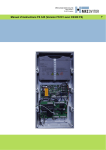
Operating Instructions for Control CS 300 GB CS 300 Gate Controls / Rev. 5.5 – 1 1. Contents 1. 2. 3. 4. 5. 6. 7. 8. 9. 10. 11. 12. 13. Contents Key to symbols General safety instructions Overview of products Initial Operation Programming with the LED module Programming with the LCD monitor Navigator (LCD monitor only) Overview of functions Error messages and rectification Technical data EU Declaration of Conformity Appendix 2. Key to symbols 3. General safety instructions 2 2 2 3 5 9 11 12 14 22 23 23 24 Guarantee The function and safety of the equipment is only guaranteed if the warning and safety instructions included in these operating instructions are adhered to. MFZ Antriebe GmbH + Co.KG is not liable for any personal injury or damage to property that occurs as a result of the warning and safety instructions being disregarded. Using the equipment for its intended purpose The CS 300 controls are designed only for controlling gates and doors with digital end position systems. Target group Only qualified and trained electricians may connect, programme and service the controls. Qualified and trained electricians meet the following requirements: -knowledge of the general and specific safety and accident prevention regulations, -knowledge of the relevant electrical regulations, -trained in the use and care of appropriate safety equipment, -capable of recognising the dangers associated with electricity. Danger of personal injury! The safety instructions must be observed! Warning! Danger to property! The safety instructions must be observed! Information Special information OR Reference to other sources of information 2 – CS 300 Gate Controls / Rev. 5.5 Instructions for installation and connection -The controls must be disconnected from the electricity supply before carrying out electrical works. It must be ensured that the electricity supply remains disconnected during the works. -Local protective regulations must be complied with. 4. Overview of products Regulations and bases for testing For connecting, programming and servicing, the following regulations must be observed (the list is not exhaustive). Construction product standards - EN 13241-1 (Products without fire resistance or smoke control characteristics) - EN 12445 (Safety in use of power operated doors Test methods) - EN 12453 (Safety in use of power operated doors Requirements) - EN 12978 (Safety devices for power operated doors and gates - Requirements and test methods) Electromagnetic compatibility - EN 55014-1 (Radio disturbance, household appliances) - EN 61000-3-2 (Disturbances in supply systems harmonic currents) - EN 61000-3-3 (Disturbances in supply systems voltage fluctuations) - EN 61000-6-2 (Electromagnetic compatibility (EMC) Part 6-2: Generic standards - Immunity for industrial environments) - EN 61000-6-3 (Electromagnetic compatibility (EMC) Part 6-3: Generic standards - Emission standard for residential, commercial and light-industrial environments) 4.1 Various options The following package options are available for the CS 300 controls: -CS 300 control with LCD monitor -CS 300 control with LCD monitor in housing -CS 300 control with LED module for setting the OPEN and CLOSED door positions (further adjustment settings are not possible) -CS 300 control without LED module and without LCD monitor (module or monitor are required for adjusting the settings) All the above options can be fitted with a plug-in weekly timer and a plug-in radio receiver. The following options are available for the housing. - Housing with CS three-button input unit - Housing with KDT three-button input unit - Housing with key switch ON/OFF - Housing with main switch -Housing with emergency off switch The operating instructions describe the connection possibilities and programming procedures for the different models: -CS 300 control with LED board -CS 300 control with attached LCD display board Machinery guidelines - EN 60204-1 (Safety of machinery, electrical equipment of machines, part 1: general requirements) - EN 12100-1 (Safety of machinery. Basic concepts, general principles for design. Basic terminology, methodology) Low voltage - EN 60335-1 (Household and similar electrical appliances Safety) - EN 60335-2-103 (Particular requirements for drives for gates, doors and windows) Professional association (D) - BGR 232 (Directive for Power-driven Windows, Doors and Gates) CS 300 Gate Controls / Rev. 5.5 – 3 GB 4. Overview of products 4.2 CS 300 basic board (with attached LCD display monitor) X9 X4 10 9 8 7 6 5 4 3 2 1 X5 1 2 3 4 5 6 7 8 X8 H4 10 H6 X11 X12 X6 X10 X7 GND GND 9 8 7 X3 6 5 X13 4 3 2 1 B1 B2 U V X2 W N L3 X1 L2 PE PE PE L1 4 – CS 300 Gate Controls / Rev. 5.5 Key: X1: terminal block mains connection X2 : terminal block motor X3: terminal block command devices X4: terminal block safety elements X5: terminal block relay X6: sockets for internal ON-OFF switch X7: sockets for internal 3-button input unit X8: socket for monitor (under monitor) X9: sockets for radio receiver X10: sockets for weekly timer X11: sockets for digital end-position system X12: socket for external radio receiver X13:terminal block for CS three-button input unit H4: status display for safety edge protection (SEP) - illuminated when SEP is working H6:Safety circuit status message - lights up when the safety circuit is closed 5. Initial Operation 5.1 General Warning! To guarantee that the equipment functions properly, the following points must be ensured: - The gate or door is installed and ope rational. - The MFZ drive motor is installed and ready for operation. - The command and safety devices are installed and ready for operation. - The control housing with the CS 300 control is installed. Information: For the installation of the gate/door, the MFZ drive motor and the c ommand and safety devices, the relevant manufacturer’s instructions are to be adhered to. GB 5.2 Mains connection Danger! To guarantee that the controls function properly, the following points must be ensured: - The mains voltage must correspond to the voltage stated on the type plate. - The mains voltage must be the same as the voltage of the drive. - For a three-phase current, a clockwise rotating field is required. - For a permanent connection, an all-pole main switch must be used. - For a three-phase connection, only 3-way automatic circuit breakers (10A) may be used. Warning! Before switching on the controls for the first time, a check must be carried out after completing the wiring to ensure that all the motor connections at the motor and at the controls are securely fixed. All control voltage inputs are galvanically isolated from the supply. CS 300 Gate Controls / Rev. 5.5 – 5 5. Initial Operation Detailed circuit diagram for mains connection and motor (230 V / three phase) X2 T1 2 4 6 1 3 5 M M1 U V W B1 B2 X11 L1 L2 L3 N 2 4 6 1 3 5 K2 K1 230V/3Phase PE PE X1 PE Key: K1: protection, CLOSE K2: protection, OPEN M1: motor T1: transformer X1: terminal block for mains connection X2: terminal block for motor X11:sockets for digital end position system with safety circuit (STOP CIRCUIT) Detailed circuit diagram for mains connection and motor (230 V / single phase) Connection: ☞☞Connect the digital end-position system to the control. ☞☞Connect the control to the mains. ☞☞Connect the control to the motor. ☞☞Short before the corresponding screw terminals, groups of cables should be make safe by means of straps Information: Technical data see page 23. X2 T1 2 4 6 1 3 5 AUF ZU M M1 N B1B2 X11 230V/1 Phase N L 2 4 6 1 3 5 K2 K1 PE PE PE X1 Detailed circuit diagram for mains connection and motor (400 V / three phase) T1 2 4 6 X2 1 3 5 M M1 U V W B1 B2 X11 L1 L2 L3 N 2 4 6 1 3 5 K2 K1 6 – CS 300 Gate Controls / Rev. 5.5 PE PE PE X1 400V/50Hz/ 3/N/PE GB 5.3 Allocation of connections for command and safety devices Command and safety devices can be connected to terminals X3, X4 and X5. Terminal block X4 (for 8.2 kOhm safety edge protection) -PART - OPEN2 Terminal block X3 8,2 KOhm - CLOSE switch - safety edge protection - impulse switch1 -photoelectric drive-through barrier3 - OPEN switch - 24 V DC / 250 mA4 - STOP switch -emergency off, slack rope switch, wicket door contact, draw-in protection Terminal block X4 (for optoelectronic safety edge protection) 10 9 8 7 6 5 4 3 2 1 wt gr br + -PART – OPEN2 0V Sig +12 V -safety edge protection OPTO -photoelectric drive-through barrier3 -24 V DC / 250 mA4 Terminal block X4 (for pneumatic safety edge protection – pressure sensor test: - A 8.2 kOhm resistor must be connected in series - The input parameter SEP TEST must be switched on) - PART - OPEN2 10 9 8 7 6 5 4 3 2 1 8,2KOhm - safety edge protection - photoelectric drive-through barrier3 + - 24 V DC / 250 mA4 Terminal block X4 (for three-wire photoelectric barrier) 10 sequence control button or selector switch 3 effective in down direction 4 for external switching devices (connection to terminals 1 and 2) 1 2 wt: gr: br: white green brown 9 8 7 6 5 4 3 2 1 GND 24V - Three-wire photoelectric barrier CS 300 Gate Controls / Rev. 5.5 – 7 5. Initial Operation Terminal block X5 (potential free switch contact) 1 2 3 4 5 6 7 8 Key switch OPEN / CLOSE - CLOSE - relay 1 - relay 2 - relay 3 - OPEN - relay 4 5.4 Connection examples for command and safety devices (terminal block X3) OPEN / STOP / CLOSE buttons (6-lead solution) Impulse button (sequence control) - CLOSE button - impulse button - OPEN button - STOP button OPEN / STOP / CLOSE buttons (4-lead solution) - CLOSE button - CLOSE button - OPEN button - STOP button 8 – CS 300 Gate Controls / Rev. 5.5 Connection: ☞☞Connect the command and safety devices to the control. 6. GB Programming with the LED module 6.1 Overview of LED module Key: LED off LED illuminated LED flashing 6.2 LED module, modes of operation With the LED module, the controls have two modes of operation: 1. AUTOMATIC 2. ADJUSTMENT Information: The current mode of operation of the control is shown via the LEDs. - In the AUTOMATIC mode, no LEDs flash. - In the ADJUSTMENT mode, at least one LED flashes. Pressing the P button toggles between the modes of operation. Operating mode 1: AUTOMATIC In the AUTOMATIC operating mode the door system is operated. LED displays: H1 H2 Status The door is open. The programmed OPEN end position has been reached. The door is between end positions. No end position has been reached. The door is closed. The programmed CLOSED end position has been reached. The door has been moved beyond the CLOSED/OPEN end position. CS 300 Gate Controls / Rev. 5.5 – 9 6. Programming with the LED module Operating mode 2: ADJUSTMENT In the ADJUSTMENT mode, the OPEN/CLOSED end position settings are adjusted. Warning! In the ADJUSTMENT mode of operation, the drive does not switch off when the end position is reached. The door can be damaged if driven beyond the end position. LED displays: H1 H2 Status The OPEN end position is programmed at this door position. The CLOSED end position is programmed at this door position. The CLOSED and OPEN end positions are not programmed at this door position. 6.3 Setting the end positions Setting the OPEN end position ☞☞Change the mode of operation to ADJUSTMENT by pressing the (P) button. ☞☞Drive the door into the desired OPEN end position by pressing the (+) button. ☞☞Save the end position by pressing simultaneously the (P) button and the (+) button. ☞☞Change to AUTOMATIC mode by pressing the P button. Setting the CLOSED end position ☞☞Change the mode of operation to ADJUSTMENT by pressing the (P) button. ☞☞Drive the door into the desired CLOSED end position by pressing the (-) button. ☞☞Save the end position by pressing simultaneously the (P) button and the (-) button. ☞☞Change to AUTOMATIC mode by pressing the P button. 10 – CS 300 Gate Controls / Rev. 5.5 GB 7. Programming with the LCD monitor 7.1 Overview of the LCD monitor Operating mode 1: AUTOMATIC In the AUTOMATIC operating mode the door system is operated. H A AUTOMATIC B RESTING C Key: A: B: C: D: E: F: G: H: O G F D E mode of operation / diagnostic info parameter / diagnostic info (+) button (-) button (P) button value / status value / status jumper Display: - displays the function being carried out - displays any error messages If the “self locking“ parameter is set to MOD2 or MOD3 in the input menu, the display changes from AUTOMATIC to MANUAL OPERATION. Operating mode 2: ADJUSTMENT In the ADJUSTMENT mode, the OPEN/CLOSED end position settings are adjusted. Warning! In the ADJUSTMENT mode of operation, the drive does not switch off when the end position is reached. The door can be damaged if driven beyond the end position. Fine adjustments can be made in the INPUT operating mode. 7.2 LCD monitor, modes of operation The control has four modes of operation with the LCD monitor: 1. AUTOMATIC 2. ADJUSTMENT 3. INPUT 4. DIAGNOSIS When the jumper H is pulled, the (+) button, the (-) button and the (P) button have no function. The display still functions. Display: - displays the end position value Operating mode 3: INPUT In the INPUT operating mode, the values of various parameters can be altered. Display: - displays the selected parameter - displays the programmed value /status Operating mode 4: DIAGNOSIS In the DIAGNOSIS operating mode, door-specific checks can be queried. Display - displays the check - displays the checking status CS 300 Gate Controls / Rev. 5.5 – 11 12 – CS 300 Gate Controls / Rev. 5.5 INPUT P >1 Sec. P >1 Sec. ADJUSTMENT RESTING P >1 Sec. AUTOMATIC RESTING + and - > 2 Sec. - -> Position DOOR CLOSED OPEN + -> Position DOOR : : : : : : INPUT RELAY 1 INPUT RELAY 2 INPUT RELAY 3 INPUT RELAY 4 INPUT SEP TEST INPUT DELAY OPEN : : INPUT QUICK CLOSE INPUT FINE OPEN : 0,3 INPUT TURNAROUND TIME : INPUT M1-3 RESTING 0 : INPUT FOREWARNING 4050 OFF OFF Mod14 Mod1 Mod7 Mod6 OFF Mod1 0 : INPUT TIME OPEN 60 : : INPUT RUNNING TIME INPUT DEUTSCH MANUAL MANUAL DOWN MANUAL MANUAL UP Return to INPUT: + and - > 1 Sec. P Save value: - Decrease value: + Increase value: Select value: P > 1 Sec. Scroll down through menu: - > 2 Sec. Scroll up through menu: + > 2 Sek Save door position: Hold P pressed and - > 1 Sec. Save door position: Hold P pressed and + > 1 Sec. 8. Navigator (LCD monitor only) DIAGNOSIS MOD1 MOD1 : : : : : : : INPUT ROTATING FIELD INPUT REVERSE OFF INPUT POWER INPUT AUTO LEVEL INPUT SELF LOCK INPUT SU/WI INPUT P/E BARRIER OPEN INPUT P/E BARRIER CLOSED : INPUT SEP LEADING : : : : : : : : : : : : ES OPEN ES CLOSE OPEN BUTTON PART OPEN CLOSE BUTTON SEP IMPULSE TIMER P/E BARRIER STOP CIRCUIT CYCLE AVE : MOD2 : INPUT BES CLOSE 4 2599 ON ON OFF OFF OFF ON OFF OFF ON ON MOD1 ON OFF 0 50 RE 4000 4000 : INPUT BES OPEN 3950 : INPUT FINE CLOSE Only query is possible P Return to AUTOMATIC operating mode: Scroll down through menu: - > 2 Sec. Scroll up through menu: + > 2 Sek GB CS 300 Gate Controls / Rev. 5.5 – 13 9. Overview of functions 9.1 Automatic operating mode Display Description AUTOMATIC OPENING The door is driven to the OPEN* end position AUTOMATIC CLOSING The door is driven to the CLOSED* end position AUTOMATIC RESTING The door stands between the end positions AUTOMATIC RESTING O AUTOMATIC RESTING o AUTOMATIC RESTING U AUTOMATIC RESTING u AUTOMATIC RESTING r The door stands at the OPEN end position The door stands at the position PART OPEN („before-end position“ up) The door stands at the CLOSED end position The door stands at the position PART CLOSE („before-end position“ down) The door stands in the position where the reversing switches off Information: If the “self locking“ parameter is set to MOD2 or MOD3 in the input menu, the display changes from AUTOMATIC to MANUAL OPERATION. Display Description MANUAL MANUAL UP The door is driven to the OPEN* end position MANUAL MANUAL DOWN The door is driven to the CLOSED* end position MANUAL RESTING The door stands between the end positions *When the gate is being driven OPEN, the power currently being used is displayed. 14 – CS 300 Gate Controls / Rev. 5.5 GB 9.2 Input operating mode Function Description Setting options Factory setting DEUTSCH Select the menu language DEUTSCH ENGLISH FRANCAIS ESPANOL NEDERLANDS POLSKI CESKY ITALIANO DEUTSCH RUNNING TIME Monitoring the max. running time for an open and close movement. The running time must be set to be slightly greater than the effective running time of the door. 1 – 250 Seconds 60 Seconds TIME OPEN After the door has opened, it runs in the CLOSE direction again after the set time has elapsed. At a setting OPEN TIME > 0, the impulse function (X3 8/9) only generates commands in the OPEN direction. 0 – 600 Seconds 0= Auto-close off FOREWARNING Before the door starts to move downwards, the traffic light flashes during the forewarning time if automatic closing is activated, or in the case of impulse operation. 0 - 120 Seconds 0 = Off TURNAROUND TIME Standing time at every change of direction 0,1 - 2,0 Seconds (in 1/10 Sec) 0,3 Seconds M1-3 RESTING MOD1: MOD2: MOD1 MOD2 MOD1 QUICK CLOSE ON:The open time is cut short and the door closes immediately after the photoelectric barrier (X4 3/4) has been activated. This function is also active if the open time = 0. ON OFF OFF OFF: When resting relay OFF (door closed) When resting relay ON (door closed) The open time continues as usual CS 300 Gate Controls / Rev. 5.5 – 15 9. Overview of functions Function Description Setting options Factory setting RELAY 1 All 4 relays can be allocated to a relais mode of 1-28. The parameter M1-3 TRAFFIC LIGHT REST affects the red traffic light (MOD 1-3). MOD1 - MOD28 MOD6 MOD1 - MOD28 MOD7 MOD1 - MOD28 MOD1 MOD1 - MOD28 MOD14 ON OFF OFF ON OFF OFF RELAY 2 RELAY 3 RELAY 4 SEP TEST MOD1:(Red light 1) flashes during forewarning and is on when door is running MOD2:(Red light 2) flashes during forewarning and when door is running MOD3:(Red light 3) is on during forewarning and when door is running MOD4: Impulse signal at OPEN command MOD5:Error message (In the case of stop messages and error messages, please refer to section 10) MOD6: OPEN end position MOD7: CLOSE end position MOD8: Final position OPEN denied MOD9: Final position CLOSED denied MOD10: Before-end position OPEN MOD11: Before-end position CLOSE MOD12: From before CLOSE position to CLOSE position MOD13: Magnetic locking function MOD14: Brake MOD15: Brake negated MOD16: Brake remains ON during open time MOD17: SEP activated MOD18:(Red light 4) flashes during forewarning and is off when door is running MOD19: From before-end position OPEN to OPEN end position MOD20: Activation of the optoelectronic transmission system MOD21: Test of draw-in protection before opening run (additional module required) MOD22: Test of external safety devices before closing run (additional module required) MOD23:(Green light) is on during OPEN end position and OFF during forewarning and OFF when door is running MOD24: Capacitor circuit for 230V single phase drives MOD25: Yard light function 2 minutes after OPEN command MOD26: Activation of radio transmission system MOD27: Impulse signal after attaining OPEN end position MOD28: Relay OFF ON: OFF: PS testing is active PS testing is inactive The testing of the PS switch takes place in the CLOSE end position. To achieve this, the airswitch contact must be activated briefly when the door comes to rest on the ground. DELAY OPEN ON: OFF: Forewarning also before opening Immediate opening Only active when the parameter FOREWARNING TIME is > 0. FINE OPEN Fine adjustment of OPEN end position 0 – 8190 (is set to programmed value after adjustment) 4050 FINE CLOSE Fine adjustment of CLOSE end position 0 – 8190 3950 BES OPEN Setting of cut-out point before-end position OPEN / PART OPEN 0 – 8190 4050 16 – CS 300 Gate Controls / Rev. 5.5 GB Function Description Setting options Factory setting BES CLOSE Setting the before-end position switch point for the CLOSE direction 0 – 8190 3950 ROTATING FIELD MOD1:Standard assembly (clockwise rotating field / increasing AVE values during opening run) MOD2:Special assembly (anticlockwise rotating field / increasing AVE values during opening run) MOD1 MOD2 MOD1 This setting may only be altered in the case of a special customised drive installation! REVERSE OFF The point where the reversing switch is activated before the CLOSE end position is reached. After going beyond the cut-out point, the door is stopped if the switching strip or photoelectric barrier is activated, but it is not reversed. The value must not exceed a maximum of 5 cm above the lower end position. 10 – 250 50 POWER The power is displayed during the opening movement. If the power monitoring facility is activated, a value must be set, which is lower than the lowest value displayed during opening. The larger the difference, in comparison to the lowest value displayed, the less sensitive the reaction of the power monitoring. The power monitoring facility is only activated if the value is set to be > 0. 0 – 999 10 AUTO LEVEL ON: OFF: Align with ground, ON Align with ground, OFF ON OFF OFF SELF LOCK MOD1: MOD2: MOD3: Automatic operation Manual operation for OPEN and CLOSE Manual operation for CLOSE MOD1 - MOD3 MOD1 SU/WI Connection to terminal strip X4 (9 + 10) MOD1 - MOD7 MOD1 MOD1: (SU/WI button 1) When the button is pressed, the door opens as far as the intermediate position PART OPEN. There is no automatic closing of the door from the position PART OPEN. MOD2: (SU/WI selector switch 1) Closed: all OPEN commands lead to the position PART OPEN. Open: all OPEN commands lead to the position OPEN. The door closes automatically from both positions. MOD3: (SU/WI selector switch 2) Closed: all OPEN commands lead to the position PART OPEN. Open: all OPEN commands lead to the position OPEN. The door closes automatically only from the position PART OPEN. MOD4: (SU/WI selector switch 3) Closed: all OPEN commands lead to the position PART OPEN. Open: all OPEN commands lead to the position OPEN. The door closes automatically only from the position OPEN. MOD5: (SU/WI button 2) When the button is pressed, the door opens as far as the intermediate position PART OPEN. Automatic closing of the door also occurs from the position PART OPEN. MOD6: Activation of automatic closing Closed: no automatic closing of the door Open: automatic closing of the door is active MOD7: External input for clock The door opens once the contact closes and remains in the position OPEN until the contact opens. The door then closes automatically. This function can be aborted by pressing the CLOSE button. The door then closes. MOD8: Selector switch: Keeping the door open / alarm Closed:The drive moves the door into the PART OPEN position. As long as the contact is closed, the door remains there. Open: normal operation CS 300 Gate Controls / Rev. 5.5 – 17 9. Overview of functions Function Description Setting options Factory setting P/E BARRIER CLOSED MOD1: MOD2: MOD 1 MOD 2 MOD 2 P/E BARRIER OPEN MOD1: Photoelectric barrier not active MOD2: When the photoelectric barrier is activated between the CLOSED end position and the pre-limit switch CLOSE, the door stops. The red light is on. The pre-limit switch CLOSE goes automatically to CLOSED end position + 600. MOD 1 MOD 2 MOD 1 SEP LEADING MOD1: MOD2: MOD 1 MOD 2 MOD 1 Stop when activated Stop and reverse when activated No function Leading photoelectric barrier (MFZ) Explanation of the relay modes: A. Traffic light functions MOD Description CLOSED end position OPEN end position Forewarning Door run MOD 1 Red traffic light 1 ON / OFF * OFF Flashing ON MOD 2 Red traffic light 2 ON / OFF * OFF Flashing Flashing MOD 3 Red traffic light 3 ON / OFF * OFF ON ON MOD 18 Red traffic light 4 OFF OFF Flashing OFF MOD 23 Green traffic light OFF ON OFF OFF * depending upon parameter MOD1-3 RESTING B. Position messages MOD Description Remarks MOD 6 OPEN end position The relay closes the contact when the door is in the OPEN end position. MOD 7 CLOSED end position The relay closes the contact when the door is in the CLOSED end position. MOD 8 Not OPEN end position The relay closes the contact when the door is not in the OPEN end position. MOD 9 Not CLOSED end position The relay closes the contact when the door is not in the CLOSED end position. MOD 10 Before-end position OPEN / PART OPEN The relay closes the contact when the door is in the before-end position OPEN / PART OPEN. MOD 11 Before-end position CLOSED The relay closes the contact when the door is in the before-end position CLOSED. 18 – CS 300 Gate Controls / Rev. 5.5 GB MOD Description Remarks MOD 12 Before-end position CLOSED to CLOSED end position The relay closes the contact when the door is in the area between the end position CLOSED and the before-end position CLOSED. MOD 19 Before-end position OPEN to OPEN end position The relay closes the contact when the door is in the area between the OPEN end position and the before-end position OPEN / PART OPEN. C. Impulse signals MOD Description Remarks MOD 4 Impulse when there is an OPEN command The relay closes the contact for 1 second when the door receives an OPEN command. This impulse can be used to control lights, for instance. MOD 27 Impulse when OPEN end position is reached The relay closes the contact for 2 seconds when the door reaches the OPEN end position. This impulse can be used, for instance, to open a following photoelectric barrier. D. Brake functions MOD Description Remarks MOD 14 Brake The switching contact of the brake rectifiers is activated via the relay to achieve a quicker brake function. The contact is closed, and the brake released as a result, as soon as the door moves (zero current brake). MOD 15 Brake negated The switching contact of the brake rectifiers is activated via the relay to achieve a quicker brake function. The contact is opened, and the brake released as a result, as soon as the door moves (operating current brake). MOD 16 Brake remains ON during open time The switching contact of the brake rectifiers is activated via the relay to achieve a quicker brake function. The contact is closed, and the brake released as a result, as soon as the door moves (zero current brake). To obtain a smoother stop by the door in the upper end position, the switching contact is not switched in the OPEN end position (OPEN TIME). CS 300 Gate Controls / Rev. 5.5 – 19 9. Overview of functions E. Error messages F. MOD Description Remarks MOD 5 Error message The relay closes the contact when a stop command is given or an error occurs. All errors described in section 10 result in activation of the relay. MOD 17 SEP activated The relay opens the contact when the switching strip is activated. An error in the switching strip or an unsuccessful test is shown via MOD 5. Functions for external accessories MOD Description Remarks MOD 13 Magnetic lock function The relay is open in the CLOSED end position. If an OPEN command is received, the relay closes and remains closed until the CLOSED end position is reached again. If a time delay is required for opening the magnetic lock, this is realised through the parameter DELAY OPEN and forewarning. MOD 20 Activation of optoelectronic transmission system Before every CLOSE command, the optoelectronic transmission system is activated and remains active for the duration of the closing run. This activation results in a closing run delay of approx. 0.5 seconds. MOD 21 Test of draw-in protection The relay generates a test signal when the CLOSED end position is reached and expects, as a reaction to the test signal, that the safety circuit is activated. MOD 22 Test of external safety devices The relay generates a test signal when the OPEN end position is reached and expects, as a reaction to the test signal, that the switching strip input circuit is activated. MOD 24 Capacitor At every drive command the relay closes for approx. 1 second. With the aid of this relay, an additional starting capacitor that is required for AC applications is switched on in addition, to ensure safe starting of the motor. MOD 25 Yard light function At every OPEN command, the relay is closed for 2 minutes and can therefore be used to control a light. MOD 26 Activation of radio transmission system Before every CLOSE command the radio transmission system is activated by an impulse. The duration of the activation must be set in the transmission system. This activation results in a closing run delay of approx. 0.5 seconds. MOD 28 Relay OFF The relay is always open. 20 – CS 300 Gate Controls / Rev. 5.5 GB 9.3 Diagnostic operating mode Display Meaning Status ES OPEN OPEN end position OFF: ON: confirmed not confirmed ES CLOSE CLOSE end position OFF: ON: confirmed not confirmed OPEN BUTTON OPEN button ON: OFF: confirmed not confirmed PART OPEN PART OPEN button (X4 / 9 + 10) ON: OFF: confirmed not confirmed CLOSE BUTTON CLOSE button ON: OFF: confirmed not confirmed SEP Safety edge protection ON: OFF: system circuit is closed system is interrupted (fault) IMPULSE Impulse button ON: OFF: confirmed not confirmed TIMER Weekly timer ON: OFF: confirmed not confirmed P/E BARRIER Photoelectric drive-through barrier ON: OFF: circuit closed interrupted (fault) STOP CIRCUIT - Stop button of controls - Stop systems of drive ON: OFF: circuit closed interrupted (fault) CYCLE Gate-cycle counter Displays the gate cycles AVE Absolute value encoder Shows the gate position value CS 300 Gate Controls / Rev. 5.5 – 21 10. Error messages and rectification Fault / error message Cause Rectification System does not respond - No voltage supply - Check the voltage supply of the drive and the controls Door travels to the CLOSE end position when the OPEN button is pressed Door travels to the OPEN end position when the CLOSE button is pressed - Rotating field is connected wrongly - Check the rotating field and establish clockwise rotating field if necessary STOP - The safety circuit is interrupted. X3 1,2: Emergency off, slack rope switch, wicket door contact, draw-in protection X6 1,2: Internal On-Off switch X11 4,8: Safety circuit for door operator X2 B1/B2: Bridge X3 3,4: External stop button X7 1,2: Internal stop button - Check and then close the safety circuit ERROR END POSITION - The door has travelled beyond one of the end positions - The end positions have not been programmed yet - Check the programming of the end positions and reset them if necessary ERROR RUN TIME - The programmed running time has been exceeded - Check the path of the door - Re-programme the running time ERROR SEP - The safety edge protection is faulty - Check the safety edge protection and the spiral cable - Safety edge protection was triggered - Remove obstruction from path of door ERROR SEP TEST - The PS switch is not activated at the CLOSE end position - Check the PS switch, spiral cable and profile - Check the setting for the CLOSE end position ERROR ROT. FIELD - An incorrect rotating field is connected to terminal X1 - Ensure that a clockwise rotating field is connected ERROR RS485 - Communications fault between the end position switch and the controls - Check the cable and socket c onnections ERROR POWER - The power monitoring has been triggered - Check that the door can move freely - Reset the power value After rectifying the cause of the fault, the controls must be disconnected briefly from the mains! 22 – CS 300 Gate Controls / Rev. 5.5 11. Technical data 12. EU Declaration of Conformity Dimensions of housing: 215 x 275 x 190 Assembling height: vertically at the wall, min. at a height of 100 mm Power supply via L1, L2, L3, N, PE: 400 V, 50 / 60 Hz; - max. power input 2200 W - 3.2 A; duty cycle 60% for a maximum running time of 120 s Protection: 10 A K-characteristic Own consumption of control: max. 250 mA Control voltage: 24 V DC, max. 250 mA; protected by selfresetting safety for external sensors Control inputs: 24 V DC, all inputs are to be connected free of potential, min. signal time for incoming control command >100 ms. Control outputs: 24 V DC, max. 250 mA RS485 A and B Only for electronic final switch. RS485 level, closed with 120 Ω Safety chain / Emergency shutdown: all input connections must be potential-free; if the safety circuit is interrupted, no further electrically powered movement of the drive is possible, not even in deadman mode. Input safety bar: For electrical safety bars with 8,2 kΩ, moving loads and dynamic optic systems. Relays output: If inductive loads are switched to (e.g.: relays or breaks), so these must be equipped with corresponding interference measures (recovery diode, varistores, RC modules). Operating contact free of potential, min. 10 mA; max. 230V AC / 4A Contacts used once for power switch are not able to switch mini power anymore. Temperature range: Operation: Storage: -10 °C ... +45 °C -25 °C ... +70 °C Air humidity: to 80% non condensing Vibrations: Assembling works with less vibration, e.g. at a masonned wall Type of protection: IP 65 Weight: about 1,8 kg Manufacturer: MFZ Antriebe GmbH & Co. Kg, Neue Muehle 4, 48739 Legden, Germany We hereby declare that, by virtue of their conceptual development and design, as well as their manufacture as we have brought them onto the market, the products cited below: CS300 Door Controls conform to the relevant basic health and safety regulations of the following EU guidelines and standards: EU Construction Products Directive 89/106/EU DIN EN 13241-1 DIN EN 12453 DIN EN 12445 DIN EN 12978 EU Electromagnetic Compatibility Directive 2004/108/EG EN 55014-1 EN 61000-3-2 EN 61000-3-3 EN 61000-6-2 EN 61000-6-3 EU Machinery Directive 2006/42/EG EN 60204-1 EN ISO 12100-1 EU Low Voltage Directive 2006/95/EG EN 60335-1 EN 60335-2-103 BGR 232 - Directive for Power-driven Windows, Doors and Gates Legden, 29 December 2009 Manufacturer‘s signature: Hans-Joachim Molterer Position of signatory: Manager CS 300 Gate Controls / Rev. 5.5 – 23 GB 13. Appendix Limit switch and safety circuit for drive Wiring allocation, AVE (absolute value encoder) plug Electronic interface A B A: AVE plug (absolute value encoder plug) B:AVE plug terminal (absolute value encoder plug terminal) The numbers on the plug are also the wire-numbers. 4: Safety circuit input 5: RS 485 B 6: GND 7: RS485 A 8: Safety circuit output 9: 12V DC AVE (absolute value encoder) plug terminal (7-12) C D C: Thermal element in the drive D:Manual emergency control (emergency crank or emergency chain) 24 – CS 300 Gate Controls / Rev. 5.5 GB CS 300 Gate Controls / Rev. 5.5 – 25 13. Appendix Overview of connections Terminal block X5 (potential free switch contact) 1 2 3 4 5 6 7 8 1 2 3 4 5 6 7 8 - relay 1 - relay 2 - relay 3 - relay 4 X10 X8 X8 X9 X9 X10 X9 X9 X4 X4 10 X5 X5 1 2 3 4 5 6 7 8 1 X82 H4 X8 3 4 5 6 7 8 10 9 8 7 6 5 4 3 2 1 H4 10 X11 X11 X11 H6 X12 X11 X10 X10 X6 X7 GND GND B2 B1 B2 B1 W W V V U U X2 X2 N 10 X12 X6 X7 N X1 L3 L3 L2 L2 L1 L1 PE PE PE X2 9 8 7 X3 6 5 X13 4 3 2 1 X1 PE PE PE H6 26 – CS 300 Gate Controls / Rev. 5.5 6 4 2 3 4 L2 U 1 2 6 5 3 4 5 L3 400V/50Hz/3/N/PE 2 6 L3 N V L1 K1 L2 L1 PE PE PE K1 PE PE PE U W N X1 T1 3 V K2 X1 1 W 5 K2 T1 1 6 2 4 B2 B1 1 3 5 X2 B2 B1 9 8 7 6 5 4 3 2 1 400V/50Hz/3/N/PE 9 8 7 X3 6 5 X13 4 3 2 1 GB Terminal block X4 (for optoelectronic safety edge protection) 10 - PART – OPEN2 9 0V -safety edge protection 8 Sig 7 OPTO +12V 6 5 -photoelectric 4 drive-through barrier3 3 2 - 24 V DC / 250 mA4 + 1 Terminal block X4 (for 8.2 kOhm safety edge protection) Terminal block X3 (assignment) - CLOSE switch OPEN / STOP / CLOSE buttons (6-lead solution) - CLOSE button - PART - OPEN2 - safety edge protection 8,2KOhm - photoelectric drive-through barrier3 - 24 V DC / 250 mA4 Terminal block X4 (for pneumatic safety edge protection – pressure sensor test) 5 - PART - OPEN2 10 9 8 7 8,2KOhm - safety edge protection 6 5 - photoelectric 4 drive-through barrier3 3 2 - 24 V DC / 250 mA4 + 1 X4 OPEN / STOP / CLOSE buttons (4-lead solution) - CLOSE button - impulse switch1 X3 - OPEN switch - OPEN button - STOP switch - STOP button - OPEN button - STOP button - Emergency off, slack rope switch, wicket door contact, draw-in protection Impulse button (sequence control) Key switch OPEN / CLOSE - CLOSE - impulse button - OPEN CS covered input unit - STOP button X13 - OPEN switch - CLOSE switch Internal ON/OFF switch X6 KDT covered input unit - CLOSE switch X7 - OPEN switch - STOP switch X12 External radio sequence control button or selector switch effective in down direction 4 for external switching devices (connection to terminals 1 and 2) 5 - A 8.2 kOhm resistor must be connected in series - The input parameter SEP TEST must be switched on 1 2 - OPEN switch - impulse button - GND - 24 V DC 3 wt: gr: br: white green brown CS 300 Gate Controls / Rev. 5.5 – 27