1
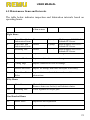
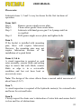
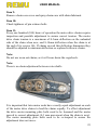
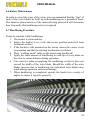
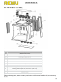
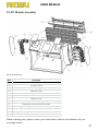
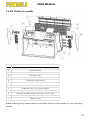
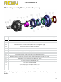
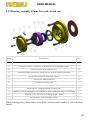
Screening Bucket User’s Manual English USER MANUAL EC Declaration of conformity for machinery (Machinery Directive 2006/42/EC, Annex II., sub. A) Manufacturer: Address: REMU Oy Inhantie 7, 63700 Ähtäri, Finland Name and address of the person authorized to compile the technical file: Name: Address: Juha Salmi Inhantie 7, 63700 Ähtäri, Finland Herewith we declare that REMU Screening Bucket Model: …………………………. Serial number:………………… is in conformity with the relevant provisions of the Machinery Directive (2006/42/EC) is in conformity with the provisions of the following other ECDirectives And furthermore, we declare that - the following (parts/clauses of) European harmonised standards have been used: SFS-EN ISO 12100, SFS-EN 349 Ähtäri ___/___ 20___ Juha Salmi Managing Director 2 USER MANUAL TABLE OF CONTENTS EC-Declaration by the Manufacturer Safety Notice Application Warning Foreword Serial Number Location 1. Safety Precautions for Operation 1.1 Safety Procedures before Operating 1.2 Safety Procedures during Operation 1.3 Safety Procedures after Operation 2. Installation of the Screening Unit 2.1 Base Installation Requirements 2.2 Hydraulic Horsepower Requirements 2.3 Testing of Hydraulic Requirements 2.4 Flow Rates of Excavators 2.5 Unit Over Speed 2.6 Hydraulic Control 2.7 Hydraulic Pressure Settings 2.8 Connection to Carrier 2.9 Installation to Carrier 2.10 Installation Check List 3. Operation 3.1 Overview 3.2 Safety 3.3 Operation Efficiency 3.4 Moisture Content 3.5 Filling the Bucket 3.6 Operating Position 3.7 Screening Process 3.8 Residue Product 3.9 Cleaning the REMU Bucket 3.10 When to Clean 3.11 How to Clean 3.12 Neglect 3.13 Cleaning Attachment 3.14 Converting the Excavator Bucket to the Crush/Screening Configuration 3.15 Converting the Bucket from Screening to Crushing Configuration 3.16 Converting the Bucket from Crushing to Screening Configuration 3.17 Screening Size (Particle Size, Grain Size) 3.18 Changing the Rotors 3.19 Changing the Counter Blades Page 2 5 5 6 6 7 7 7 8 9 9 9 10 10 11 11 11 11 12 12 13 13 14 14 14 15 15 15 16 16 16 16 17 17 17 17 18 18 18 18 3 USER MANUAL 4. Maintenance 4.1 Maintenance Schedule 4.2 REMU Parts 4.3 Contaminated Products 4.4 Maintenance Safety 4.5 Maintenance Items and Intervals 4.6 Rotors Maintenance 4.7 Hard facing Procedure 5. Maintenance under Special Conditions 6. Troubleshooting 6.1 Dealing with Fault Diagnosis 6.2 Possible Faults 6.3 Hydraulic 6.4 Mechanical 6.5 Fault Diagnosis 6.5.1 Rotors Cease to Turn 6.5.2 Rotors Turn Slowly 6.6 Material Size 7. Storage 7.1 Storage Preparation 7.2 Removing the Bucket from Storage 8. Transport 8.1 Transport when Mounted on Carrier 8.2 Shipped as Stand Alone Bucket 9. Specifications 9.1 REMU Screening buckets 9.2 Particle size 9.3 EL Model Assembly 9.4 EX Models Assembly 9.5 EP Models Assembly 9.6 EE Models Assembly 9.7 Bearing assembly 50 mm, fixed end, open cap 9.8 Bearing assembly 50 mm, free end, open cap 9.9 Bearing assembly 50 mm, free end, closed cap 9.10 Bearing assembly 60 mm, fixed end, open cap 9.11 Bearing assembly 60 mm, free end, open cap 9.12 Bearing assembly 60 mm, free end, closed cap Warranty Terms 19 19 20 20 20 21 24 24 25 26 26 26 26 27 27 27 28 28 29 29 29 30 30 30 31 31 32 33 34 35 36 37 38 39 40 41 42 43 4 USER MANUAL SAFETY NOTICE The warnings in this operator and maintenance manual are not allinclusive. Though every effort has been taken to ensure a detailed coverage, REMU cannot anticipate every possible circumstance that might involve a potential hazard. If operation or maintenance is not performed as specifically recommended by this manual, you must ensure that it is safe for you and others. You must also ensure that the REMU Screening Bucket will not be damaged or made unsafe by the method you choose. APPLICATION WARNING REMU occasionally modifies some REMU Screening Buckets specifically at the request of the customer to meet the special application needs. It should be noted that these modifications totally change the performance and operation characteristics on the "Normal standard REMU" unit and these characteristics must be fully understood by the user. Owners and operators are hereby advised that the use of modified REMU Screening Buckets in applications for which they were not intended is strictly prohibited. If the bucket is operated in conditions for which it was not designed, severe damage will occur to the drive mechanism. Damage caused by inappropriate applications will not be supported by REMU’s warranty. Owners and Operators are hereby warned to check with the distributors or manufacturers to ensure the particular screening unit will meet the desired application. 5 USER MANUAL FOREWORD We wish to thank you for choosing the REMU screening bucket. This operation and maintenance manual describes procedures for: - operation - maintenance - repair - routine inspection - adjustment - trouble shooting Please take time to read this manual carefully as it must be read in conjunction with the operator’s manual of the "carrier" machine. This will help you to utilise the REMU Screening Bucket efficiently and economically. Your safety and the safety of others depend upon care and judgement in the operation of this attachment. A careful operator is good insurance against accident. REMU’s policy is to continually improve the product design that will provide changes to this REMU screening bucket, which may not be included in this manual. This publication is based on current information at the time of the printing. SERIAL NUMBER LOCATION Serial number is located on the top right hand side of the unit when viewed from the carrier’s operator seat adjacent to the motor. 6 USER MANUAL 1. SAFETY PRECAUTIONS FOR OPERATION Many failures and accidents that occur during operation or servicing are a result of neglecting fundamental precautions. Do not operate this unit unless you have read and understood the instructions in this manual. Do not allow anyone to operate this unit without recognised instruction. Unauthorised modifications to this unit may impair the function and/or safety and reduce service life. 1.1 Safety Procedures before Operating it is strongly recommended that the limitations and performances of the REMU Screening Bucket and the carrier unit be fully understood before any attempt is made to operate the screening bucket in a production environment learn and apply the procedures and rules relative to the work site establish a means of communication in the event of accident or fire complete standard daily checks of the screening unit as well as the carrier machine clear obstacles from work area and be aware of hazards including overhead wires never use diesel or petrol as cleaning solvents inspect unit, rotors and hoses for damage and make the appropriate repairs before operating in the case of units fitted to the carrier via a quick hitch, ensure that the quick hitch is capable of withstanding thrust in the direction it is applied, and that the safety pin is serviceable and installed prior to operation ensure that the work area is clear of personnel at least for a radius of 25 metres (80 feet) 1.2 Safety Procedures During Operation do not lift the carrier machine off the ground by transmitting the full weight of the machine on to the screening unit, as severe structural damage may occur to the Screening Bucket 7 USER MANUAL ensure that the work area is clear of personnel at least for a radius of 25 metres (80 feet). do not allow unauthorised people in the work area test operation of bucket rotors with unit empty operate the Screening Bucket only while seated in the carrier operator’s seat periodically check the bucket and tighten bolts that may have worked loose the Screening Bucket must be operated at a speed that can be correctly controlled do not use the bucket as a battering ram keep work site flat by continually grading to ensure efficiency and safety do not operate the carrier machine in an overloaded condition when loading trucks or hoppers, be careful not to hit the truck or hopper with the bucket do not swing the bucket over personnel or the cabs of the trucks do not work when dust, fog or smoke reduces visibility to an unsafe situation ensure that the job site is sufficiently alight for night work stop the machinery frequently during night work and walk around and inspect the bucket and the carrier stay alert 1.3 Precautions after Operation After the end of a work period, ensure that the following procedures are followed: lower the bucket on to a flat solid ground that is free from falling material and flooding lubricate the bucket’s moving parts in accordance with the preventative maintenance schedule clean and inspect the screening bucket for any irregularities in structure and performance 8 USER MANUAL 2. INSTALLATION OF THE SCREENING UNIT A proper investigation needs to be carried out to ensure that the carrier is capable of handling the loaded weight of the screening bucket safely. The installer is to ensure that the stability of the carrier is not impaired and the carrier’s lifting capacity is not exceeded. (Carrier lifting capacity charts can be found in the carrier Operators or Workshop Manual.) The hydraulic horse power capacity needs to be known to determine if it is able to provide sufficient capacity to operate the screening bucket at its optimum. 2.1 Base Installation Requirements The screening bucket requires by-directional flow from the carrier. An operator controlled directional control valve and plumbing to the boom tip capable of handling the required flow and pressure needs to be installed on the carrier. It should be noticed that carriers fitted with variable displacement hydraulic pumps need to have the hydraulic horsepower demand curves checked to determine that the carrier can deliver the required flow at the required pressure without exceeding the horsepower output of the carrier. A sufficient flow and pressure without unduly straining the carrier may necessitate the addition of more hydraulic fluid, the amount of which will vary depending on the type of carrier. 2.2 Hydraulic Horsepower Requirements If the carrier cannot provide the required flow, pressure and/or the required hydraulic horsepower then the screening bucket’s maximum efficiency will not be achieved. Carrier flow, pressure and horsepower requirements can be obtained from the manufacturer or distributor of the carrier. If the carried hydraulic capacity is unknown then a flow test will have to be carried out by a suitably competent person. These flow and pressure tests will have to be recorded to ensure an accurate record is kept or warranty registration purposes. 9 USER MANUAL 2.3 Testing of Hydraulic Requirements It is in the interest of a trouble free commissioning process and long term service life that the hydraulic performance of the proposed carrier be measured, adjusted and recorded to ensure that the carrier is providing the required flow and pressure. Using a serviceable flow meter installed in the delivery lines that the screening unit will be fitted to is the only effective method to determine accurately the carrier’s hydraulic performance. Please note that some modern construction machinery have flow and pressure sensors that provide readings on a liquid crystal display located in the cab. It should be noted that this feature only provides a theoretical indication and should not be relied upon. The flow and pressure must be physically checked to ensure accuracy. (Please refer to flow, pressure and horsepower details). 2.4 Flow Rates of Excavators It should be noted that modern excavators are capable of producing more flow than required for the screening bucket. The flow to the screening bucket circuit must be restricted to the maximum allowable flow (please refer the specification table). If the flow exceeds the recommendations, the unit will suffer over speed that will result in an early failure of the drive chains and motors. Larger excavators (10 tonnes and above) and some large wheel loaders are fitted with a variety of “load sensing” control systems that are known in the industry under various trade names. The function of these systems is to provide the required flow when demanded by the operator. Therefore the installer will have to determine the type and control methods of the load sensing system employed on the carrier and adjust or modify the system to ensure that the required flow rate of the screening bucket is not exceeded. In case the installer is unable to operate the load sensing control system, the control needs to be done in cooperation with the manufacturer or distributor. 10 USER MANUAL 2.5 Unit Over Speed If a failure occurs due to over speed, then the warranty will not apply. Note: Check the flow rate to the REMU circuit under the following conditions: the unit just below maximum relief valve setting the unit under no load condition with other functions of the carrier machine being operated at the same time In all cases the flow rate must not exceed maximum recommended. 2.6 Hydraulic Control If the REMU bucket is being installed on a carrier that is fitted with a PILOT OPERATED hydraulic system, particular care is to be taken in installing flow control/checks in the screening bucket’s control circuit to slow down the speed of the transition from one direction to the other. For further details of the location of these flow control checks please contact the dealer and/or manufacturer. 2.7 Hydraulic Pressure Settings The REMU bucket’s operating pressure should not exceed the recommendations as highlighted in Section 2. Inline relief valves should limit the circuit that operates the unit. It should be noted that some excavator manufacturers use flow cut-off systems when the circuit relief is activated. A thorough understanding of the carrier’s hydraulic design parameters must be understood prior to the design of the installation. 2.8 Connection to Carrier In the case of excavators it should be noted that the manufacturer recommends that the REMU Screening Bucket be installed in a "Face Shovel" application. The installation in a face shovel application will 11 USER MANUAL increase efficiency by reducing cycle times and reducing excessive strain that can be exerted on the unit. 2.9 Installation to Carrier use safety glasses and gloves for protection against injury when installing connecting pins ensure the quick hitch coupling specification of the carrier is to the same dimensions as the pick up on the screening bucket if a "quick hitch" is installed it is the operator’s/owner’s responsibility to ensure the forces can be transmitted through the quick hitch information regarding this specification is available from the manufacturer upon request if a "quick hitch" is used, ensure that it has a fully operational safety pin fitted the bidirectional auxiliary hydraulic flow is connected to the buckets hydraulics If at any time the installer is unsure of the requirements of the installation, the installer has the responsibility to contact the dealer or manufacturer to obtain the correct up to date information. 2.10 Installation Check List The following installation check list needs to be observed by the installer: attach and secure the screening bucket after ensuring that the coupling method specifications match those of the carrier connect the hydraulic connecting hoses after ensuring the couplings from the carrier match the hoses for the screening bucket and are in a clean serviceable condition if the carrier is pilot controlled, install flow control checks in the screening bucket’s control system to reduce changeover shocks check and record REMU circuit system flow and pressure at the appropriate place on the service report 12 USER MANUAL in the case of excavator unit, ensure that the maximum flow rate will not be exceeded under the following conditions: 1. When unit is operating just below maximum relief valve setting. 2. When unit is under no load. 3. When other functions of the carrier machine are being operated at the same time in the case of Skid Steers, Backhoe/Loaders, Wheel loaders, position the bucket so that the bottom of the unit is parallel with the ground, with a slight tilt to the front. Mark or adjust the auto-levelling device to indicate the digging position at low engine R.P.M., operate the screening unit in one direction for approx. twenty seconds to expel air from the hydraulic lines carry out preventive maintenance procedure as explained in this manual ensure that the bucket’s flow rates have been checked under a variety of conditions as explained before operation the operator/s should spend the time to familiarise themselves with the operating techniques of this screening bucket the appropriate delivery paperwork needs to be completed by the dealer indicating that the owner and/or the operator are conversant with the safety and operation procedures of the REMU screening bucket the bucket is now ready to go to work. Test it carefully with following all the safety notes in chapter 1 3. OPERATION 3.1 Overview It should be fully understood that while the REMU screening bucket has been applied successfully in a number of applications, the REMU screening bucket is not the answer to all screening problems. Some materials are not as free flowing due to the moisture content or geological characteristics, and take a considerably longer time to process. REMU makes no assessment of production capabilities, as 13 USER MANUAL there are a considerable number of factors outside of REMU’s control as a manufacturer. REMU bucket’s "rotors and counter blades" are consumable wear items and will from time to time need to be built up or replaced. The frequency of the need to build up or replace the rotors or counter blades will depend on the abrasive quality of the material being screened. The size of screened primary product will gradually increase in proportion to the amount of wear of the consumable components. The wear-rate of the wear parts can be retarded by periodically applying a "hard facing" in an even manner. 3.2 Safety Always check the surroundings before operating the screening unit or carrier. The job site should be set up in order to provide a sufficient work area giving operational access to the raw material stockpile and sufficient space for the storage of processed primary (smaller) product as well as an area for the processed secondary (larger) product. (The carrier can be positioned allowing reach to stockpiles, hoppers or trucks with primary or secondary product.) Ensure that the ground conditions are sufficiently stable and level to support the weight and operation of the carrier in a safe manner. 3.3 Operation Efficiency always allow the hydraulic oil to warm up for approximately five minutes, as cold hydraulic oil will not allow the components to operate correctly it is important for optimum performance that the carrier unit operates at enough engine R.P.M. to provide the required flow while the screening unit’s rotors are operated 3.4 Moisture Content The moisture content will not effect the material operation until the moisture content exceeds the plasticity level. From this point the material "flow" through the unit will slow down depending on the type of material. 14 USER MANUAL Therefore excess moisture content will determine the speed in which the material will be processed through the unit. 3.5 Filling the Bucket Operate the carrier in conventional manner to fill the screening bucket to the rollback waterline. (Except in excavator application, where face shovel configuration is to be used.) Note: Do not overfill unit above water line as spillage during operation of unscreened material will contaminate the already screened material 3.6 Operating Positioning Position the unit over the primary product storage area, hopper or truck. 3.7 Screening Process Operate bucket in a cyclic manner by operating bucket rotors in one direction for five seconds. Then reverse the rotors in the other direction for five seconds. Repeat this procedure until the majority of the primary product is no longer expelled from the unit. Do not continue to operate unit excessively to process the final amount of material as the breaking down of the final amount of material may cause accelerated wear to the rotor blades. At this point the "oversize" material (the remainder left in the unit) should be discarded as secondary or residue product by rolling the unit forward. The process of filling, processing and discarding the residue is repeated. If the unit stalls during the screening operation, simply reverse rotation and the rotors will self-clean. Note: If due to moisture content or material characteristics the material will not screen as expected or if the screening unit begins to stall, tilt the unit forward and operate normally until it clears, then slowly tilt back to the horizontal position. 15 USER MANUAL There are a number of reasons why some material placed in the screening unit will not "screen". Initially it is recommended that a particular load be dumped onto the supply stockpile and be partly re-screened in another pass to fill the bucket. The production rate through the screening unit of some material is dependent on the material characteristics and the moisture content. If the screening flow of material stops for no apparent reason (i.e. the bucket does not screen all the material currently in it), a probable cause is that the material is too light. The screening bucket needs to be topped up with more raw materials to push the lighter material onto the rotors. 3.8 Residue Product Dump the residue in a conventional manner in the secondary product storage area, hopper or truck. 3.9 Cleaning the REMU Bucket It is extremely important for operators to be aware that the rotor assemblies must be periodically cleaned while the material is still "soft". 3.10 When to Clean Screening should be carried out: when the efficiency of the screening action is impaired before the build-up of material between the blades of one rotor touches the adjacent rotor blade on a regular basis where the material being screened dictates the frequency 3.11 How to Clean The carrier unit needs access to coarse, dry, hard, oversized material (for example soft rock, bricks or river gravel). Process this material through the unit in the normal manner until the build-up of material is reduces to a point where the square edges of the rotor shafts are visible. 16 USER MANUAL 3.12 Neglect If cleaning is not carried out efficiently: the bucket operation will be greatly impaired material will build up in the rotors it will cause accelerated wear on the rotor outside diameter surface 3.13 Cleaning Attachment REMU has developed a cleaning attachment suitable for cleaning high plasticity material from the rotor assemblies. If the material being processed cannot be cleaned or builds up very quickly REMU suggests that the cleaning attachment should be fitted to clean the unit to improve screening production of high moisture material. For further details on this attachment please contact REMU’s dealer network. 3.14 Converting the Excavator Bucket to the Crush/Screening Configuration The excavator screening buckets can be adjusted so that the unit can crush "soft" material. The types of material that can be crushed are gypsum, bark, mulch, foundry sand, sand stone, mud stone and a variety of other materials. However, harder materials such as stone, concrete, etc. cannot be crushed. 3.15 Converting the Bucket from Screening to Crushing Configuration To convert the bucket to crush soft material on the excavator unit, the following steps should be followed: 1. Position the bucket so the rotors are at the bottom and the unit counter blade retaining bolts are located at approx. waist height 2. Loosen all of counter blade retaining nuts. 3. Move the counter blades fully to the bottom. 4. Retighten the counter blade nuts in this position. 5. Test run the bucket with material to be crushed. 17 USER MANUAL 6. If the operation of the bucket is impaired in start-up configuration then the counter blades need to be readjusted up slightly to reduce the amount of crushing effect between the counter blades and the rotors. It should be noted that the height of the counter blade adjusting nuts must all be the same. 7. Restart the operation of the bucket after the adjustment. 8. If the bucket has problems in operation, adjust the counter blades towards the screening position. 3.16 Converting the Bucket from Crushing to Screening Configuration To convert the excavator buckets from crushing to screening, the following steps should be followed: 1. Position the bucket so the rotors are at the top and the cutting edge of the bucket is placed on the ground. 2. Loosen all of counter blade retaining nuts. 3. Move the counter blades fully downward. 4. Retighten the counter blades in this position. 5. Check the operation of the bucket to ensure the screening function is acceptable. 3.17 Screening Size (Particle Size, Grain Size) The screening size can be changed by replacing the main blades and counter blades. 3.18 Changing the Rotors Contact your local dealer. 3.19 Changing of Counter Blades 1. Ensure that the replacement counter blades are correct for the model and the size of product required before proceeding 18 USER MANUAL 2. Note: In the models that have even number of main blades, the counter blades are similar. In the models where the number of main blades is odd, the counter blades suit only to their own side. 3. Position the bucket so the rotors are in a vertical position. 4. Lower the bucket to the ground and shut down engine of the carrier. 5. Remove counter blade retaining nuts and washers. 6. Using a crow bar, ease counter blades out of position into the centre area of the bucket in front of the rotors. 7. Clean the counter blade mounting area thoroughly. 8. Install new counter blades in position ensuring the tapered end of the counter blade fingers is pointing towards the cutting edge side of the unit. 9. Install nuts and washers. 10. Start carrier and position the unit so the rotors are at the top and the cutting edge of the unit is placed on the ground. 11. Move the counter blades fully downwards (towards the top). 12. Retighten the counter blades in this position. 13. Check the operation of the bucket to ensure the screening function is acceptable. 4. MAINTENANCE Regular intervals of proper lubrication and maintenance are essential for extended service life and safe operation without loss of efficiency. This section provides procedures for safe lubrication and maintenance of the screening bucket. Please note all cautions. 4.1 Maintenance Schedule The maintenance intervals are determined by the operating hours. This manual designates 8 hours for a day, 50 hours for a week and 100 hours for two weeks. If the screening bucket operates beyond the standard operating hours, or when the type of working conditions are arduous as highlighted in Section 7, then initiate and perform a maintenance schedule with shorter 19 USER MANUAL intervals. Contact the dealer or manufacturer for any adjustment procedures not covered in this operator’s manual. 4.2 REMU Parts Always use genuine REMU products for repair and maintenance. Spare parts are available from your local dealer. 4.3 Contaminated Products Always dispose of contaminated products as "industrial waste" in accordance with Government Regulations. 4.4 Maintenance Safety 1. 2. 3. 4. Wear suitable clothing. Use the correct tools. Use sufficient care while using cleaning fluids. Use safety tags or isolate carrier so it cannot be started. Do not attempt to inspect or touch the rotors or carry out preventative maintenance while the carrier engine is running and if the screening bucket is not on the ground. 20 USER MANUAL 4.5 Maintenance Items and Intervals The table below indicates inspection and lubrication intervals based on operating hours. Item Point Type of lubric or item to check Volume Grease 2 pumps Recommendation Eight Hours 1. 3. Rotor Drive End Lubrication Points Rotor Idler End Lubrication Points Mounting Pins 4. Rotors Multi purpose NLGI No.2 Lithium EP Grease 2 pumps Grease Multi purpose NLGI No.2 Lithium EP Grease 2 pumps Grease Multi purpose NLGI No.2 Lithium EP Grease Inspect condition for wear or damage. 5. Counter Blades Inspect condition for wear or damage. 6. Cutting Edge Inspect condition for wear or damage. 7. Motors and Hoses Inspect for damage and leaks and repair if necessary. 8. Chain Case Drain Holes Inspect chain case drain holes are clear and free obstructions. 2. Fifty Hours 9. Chain Case 10. Mounting Pins Chain Lubrication spray Remove chain case cover(s) and lubricate chains. Check tightness of keeper pins. One Hundred Hours 11. Motor Drive Inspection and Adjustment 12. Chains Check and replace if needed. 21 USER MANUAL Please note: Lubricate items 1, 2 and 3 every two hours for the first ten hours of operation. Items 1&2: Step 1 Remove grease nipple access plate. Step 2 Clean excess grease from recess holes. Step 3 Lubricate with hand grease gun 2 to 4 pumps until air is expelled. Step 4 Refit grease nipple access plate and tighten bolts. Item 3: If the bucket is installed with mounting pins, these will require lubrication. However, the mounting pins may not require lubrication because of the installation of a quick hitch. Items 4, 5 & 6: A visual inspection is required or each rotor assembly, counter blade and cutting edge to ensure that each blade, counter blade or edge is in a serviceable condition and has not been bent or excessively worn. Note: The design of the rotors allows them a normal radial movement of about 5mm (3/16"). Item 7: A visual inspection is required of the hydraulic motor(s) for external leaks and hoses for cuts and leaks. Item 8: Closely inspect the chain case’s abstraction of water hole and ensure that it is clear and free of obstructions. 22 USER MANUAL Item 9: Remove chain case cover and spray chain case with chain lubricant. Item 10: Check tightness of pin retainer bolts. Item 11: Every one hundred (100) hours of operation the motor drive chains require inspection and possible adjustment to ensure correct tension. The motor drive chain tension is a maximum of 0-3mm deflection on the unloaded side of the chain when new, and 8-14mm deflection when the chain is at the end of its service life. If chains exceed this deflection dimension they should be adjusted to minimum deflection or replaced with new chains. Note: Do not use worn out chains, as it will wear down the cogwheels. Note: There is no chain adjustment between rotor shafts. It is important that twin motor units have exactly equal adjustment on each of the motor drive chains to load the chains equally. To affect adjustment the drive motor mounting plate bolts need to be loosened and the motor moved to correct adjustment (0-3 mm movement when the chain is new). The motor mounting plate bolts need to be re-torqued to ensure the adjustment does not move. 23 USER MANUAL 4.6 Rotors Maintenance In order to retard the wear of the rotors it is recommended that the "tips" of each of the rotor blades be built up with hardfacing on a periodical basis. The abrasive characteristics of the material being processed will determine how frequently this hardfacing action is required. 4.7 Hardfacing Procedure Points to consider while hardfacing: 1. The bucket is clean and dry. 2. Ensure the bucket is in a safe and secure position protected from inclement weather. 3. If the bucket is still mounted on the carrier ensure the carrier is not in operation and that the starting mechanism is isolated. 4. Place “welding earth” cable on the rotor being hardfaced! 5. Apply the same amount of hardfacing to each tip of every blade on the rotor to ensure balance during operation. 6. Care must be taken in applying the hardfacing so that it does not exceed the width of the rotor blade. Should the width of the rotor blades increase due to hardfacing, the individual rotor blades may touch during operation and cause damage. 7. When hardfacing is completed, operate the bucket in a variety of angles to ensure it operates properly. 24 USER MANUAL 5. MAINTENANCE UNDER SPECIAL CONDITIONS Maintenance under extreme or special conditions needs to be carried out on a more frequent basis than during standard conditions. Therefore the operator/owner has the obligation to apply preventative maintenance on a more frequent basis to suit the site conditions. The following table is presented as a guide: Condition Muddy water, rain, snow Recommendation Before operation During operation After operation Salt water & Highly Corrosive Material Before operation During operation After operation Excessive dust During operation Rocky material After each two hours Cold weather After operation Check all inspection plates are in good condition Lubricate every 2 hours Drain the chain compartments of water and lubricate drive chains Check all inspection plates are in corrosive material in good condition. Lubricate every 2 hours. Drain chain compartments of water and lubricate drive chains Clean bucket with high-pressure fresh water to remove material residue Lubricate every 2 hours. Check for structural damage, cracks of operation and loose/missing bolts. Ensure inspection plates are in good condition. Use high quality high-viscosity lubricating products. Clear dirt from bucket to prevent freezing. If further details or clarification is required please contact the dealer and/or manufacturer. 25 USER MANUAL 6. TROUBLESHOOTING Troubleshooting is a series of steps where faults may be traced. A symptom of a fault should be investigated immediately to determine the severity of the problem and whether it is safe to continue without causing further damage. This section describes how to identify symptoms and solve specific problems quickly and systematically. 6.1 Dealing with Fault Diagnosis confirm the faulty component or function ensure personal safety will not be compromised if operation is continued reproduce the fault symptoms systematically forecast possible causes of fault confirm assumed causes use repair method and procedures as shown in the this manual 6.2 Possible Faults The REMU screening bucket has two basic systems: hydraulic and mechanical. 6.3 Hydraulic Depending on the model the REMU bucket uses one or two low speed, high torque hydraulic motors. (The two motor units have the drive shafts mechanically connected and are hydraulically plumbed in parallel.) Both the single and two motor versions are connected to the auxiliary service ports of the carrier machine. The service ports need to provide the correct flow rate to ensure optimum performance of the screening unit. It is important that the flow and pressure settings are set at the recommendations shown in the specifications section. 26 USER MANUAL 6.4 Mechanical The screening principle of this unit operates by material passing through the rotors, which are rotating at a set speed. If these rotors do not turn at the required speed the efficiency of the screening unit will we affected. 6.5 Fault Diagnosis Please refer to the following possible problems and actions. If further information is required please contact to the distributor or manufacturer. 6.5.1 Rotors Cease to Turn If the rotors cease to turn the problem could be caused by: A. Incompressible material caught in the rotors. Action: Check to see if there is material caught in the rotors and remove. B. Broken drive chain sprocket or shaft. Action: Turn off the machine and check to see if chains and sprockets are in a serviceable condition by removing inspection cover. After replacing chains determine the reason for failure and make the necessary adjustments or repairs. Always determine the cause of chain failures; over speed and lack of lubrication will cause premature failures. C. Carrier hydraulic system is not providing any flow. Action: Check flow and pressure at carrier service ports with flow meter and pressure gauge. 27 USER MANUAL 6.5.2 Rotors Turn Slowly If the rotors turn slowly the problem could be caused by: A. Reduced hydraulic oil flow from the carrier. Action: Check flow at carrier service ports with flow meter. B. The carrier’s operating pressure could be below the required level. Action: Check carrier system pressure while screening unit is in stalled condition with pressure gauge. C. The rotors and/or bearings could be binding. Action: After checking A and B above, remove chain inspection cover and remove drive chain between motor(s) and try to spin the rotors. If rotors are free the motor(s) require further investigation and/or overhaul. If the rotors cannot be turned remove the remaining chains between the rotors to determine which rotors cannot be spun separately. Remove the drive sprocket from the rotor(s) that cannot be spun, check the bearing and replace it if needed. 6.6 Material Size If the primary material size increases over a period of time, it may indicate that the rotor blades and counter blades have worn. If primary material size is larger than required specification then the rotor assemblies will have to be hardfaced or replaced. 28 USER MANUAL 7. STORAGE If the bucket is not to be used for a long period of time it must be carefully stored to prevent damage or loss of serviceability. Indoor storage is best, however if stored outside ensure that the unit is placed on suitable blocks in a well-drained, level and “hard standing” area. 7.1 Storage Preparation 1. 2. 3. 4. 5. Place the bucket on suitable blocks in the "digging" position. Clean the bucket thoroughly. Inspect for loose or missing parts and tighten or replace if necessary. Lubricate the bucket. Ensure hydraulic lines are full of oil and are capped tightly with steel caps. 6. Apply rust preventative sealer to all exposed surfaces. 7.2 Removing the Bucket from Storage 1. Clean the bucket thoroughly. 2. Remove rust preventative sealer from all exposed surfaces. 3. Inspect for loose or missing parts and tighten or replace if necessary. 4. Lubricate the bucket. 5. Ensure that the bucket is matched to the carrier it is to be fitted to. 29 USER MANUAL 8. TRANSPORT 8.1 Transport when Mounted on Carrier Transportation of the screening bucket mounted on the carrier should be done in a normal manner as if the screening bucket were a normal bucket. Care should be taken not to use the screening bucket as tie down point for the carrier. 8.2 Shipped as Stand Alone Bucket A. The bucket clearly has its weight stamped on the maker’s plate. Ensure that the centre of gravity is known (about one third from the rear of the unit depending on the model) and adjust slings to compensate. B. Ensure hydraulic lines are properly capped with steel caps to avoid oil leakage and the ingress of contamination. C. Position the bucket so that it is transported in the “digging” position. D. Position the bucket so that other items will not damage rotors or hydraulic motor(s). E. Ensure there is timber between the bucket and the deck of the transporter. F. Use the appropriate tie down points G. Do not use the motor(s) as tie down points. H. Do not transport loose items in the screening unit. 30 USER MANUAL 9. SPECIFICATIONS 9.1 REMU Screening Buckets 31 USER MANUAL 9.2 Particle size Particle size of screened or crushed material is matter of many circumstances like weather conditions, moisture, skills of operator, blade design, setting of counter blades, content of material etc. Approximate particle size is about 7 mm smaller than used blade spacing. 32 USER MANUAL 9.3 EL Models Assembly (EL2085 illustrated) Item Description Qty 7 Back cover plate EL2085 2 6 Bucket rotor 2 5 Front side extension EL2085 (optional) 1 4 Comb counter blade 2 3 Hydraulic motor with chain wheel 1 2 UCF207 flange bearing unit for 35 mm shaft 4 1 Bucket body 1 When ordering parts, please contact your dealer with the serial number of your screening bucket. 33 USER MANUAL 9.4 EX Models Assembly (EX140 illustrated) Item Description 12 Bucket lower hatch 11 Bucket upper hatch 10 9 Cleaning scraper frame Comb blank 8 Counter blade 7 Bucket rotor 6 Motor plate 5 Hydraulic motor with chain wheel 4 Bearing assembly 60 mm, free end, closed cap 3 Bearing assembly 60 mm, fixed end, open cap 2 Inner shaft 1 Bucket body When ordering parts, please contact your dealer with the serial number of your screening bucket. 34 USER MANUAL 9.5 EP Models Assembly (EP4150 illustrated) Item Description 13 Backside hatch 12 Topside hatch 11 Side door, right 10 Side door, left 9 Cleaning scraper frame 8 Comb blank 7 Bucket rotor 6 Comb counter blade frame 5 Hydraulic motor with chain wheel 4 Bearing assembly 50mm shaft, free end, open cap 3 Bearing assembly 50mm shaft, fixed end, open cap 2 Inner shaft 1 Bucket body When ordering parts, please contact your local dealer with the serial number of your screening bucket. 35 USER MANUAL 9.6 EE Models Assembly (EE3220 illustrated) Item Description 13 Backside hatch 12 Topside hatch 11 Side door, right 10 Side door, left 9 Comb blank 8 Cleaning scraper frame 7 Comb counter blade frame 6 Bucket rotor 5 Hydraulic motor with chain wheel 4 Bearing assembly 60mm, free end, open cap 3 Bearing assembly 60mm, fixed end, open cap 2 Inner shaft 1 Bucket body When ordering parts, please contact your dealer with the serial number of your screening bucket. 36 USER MANUAL 9.7 Bearing assembly 50mm, fixed end, open cap Item Description QTY. 15 Nordlock M12 (NL12) DIN25201 5 14 Hex Screw M12x30 DIN933 10.9 2 13 Lubrication hose connector 3mm/6mm M10 90-degrees angle 1 12 Hex Socket Screw M12x25 12.9 DIN912 3 11 Screening shaft end plate, Same size fits 50 mm and 60 mm shaft 1 10 Sprocket key 50 mm shaft 1 9 Screening shaft chain wheel, Z17 16B-1, double sprocket 1 8 Open end bushing on 50 mm shafts, bushing length 41mm 1 7 Shielding washer between rotor end plate and bearing housing, 50 mm shaft 1 6 Bushing on 50 mm shafts, bushing length 19mm 1 5 Oil seal for 50 mm shaft (60_80_10) 2 4 Hex Screw M8x30 DIN933 4 3 50 mm shaft, open bearing housing cap 1 2 Bearing for 50mm shaft, code 22210 1 1 50 mm shaft, fixed bearing housing 1 When ordering parts, please contact your dealer with the serial number of your screening bucket. 37 USER MANUAL 9.8 Bearing assembly 50mm, free end, open cap Item Description QTY. 15 Nordlock M12 (NL12) DIN25201 5 14 Hex Screw M12x30 DIN933 10.9 2 13 Lubrication hose connector 3mm/6mm M10 90-degrees angle 1 12 Hex Socket Screw M12x25 12.9 DIN912 3 11 Screening shaft end plate, Same size fits 50 mm and 60 mm shaft 1 10 Sprocket key 50 mm shaft 1 9 Screening shaft chain wheel, Z17 16B-1, double sprocket 1 8 Open end bushing on 50 mm shafts, bushing length 41mm 1 7 Shielding washer between rotor end plate and bearing housing, 50 mm shaft 1 6 Bushing on 50 mm shafts, bushing length 19mm 1 5 Oil seal for 50 mm shaft (60_80_10) 2 4 Hex Screw M8x30 DIN933 4 3 50 mm shaft, open bearing housing cap 1 2 Bearing for 50mm shaft, code 22210 1 1 50 mm shaft, free bearing housing 1 When ordering parts, please contact your dealer with the serial number of your screening bucket. 38 USER MANUAL 9.9 Bearing assembly 50mm, free end, closed cap Item Description QTY. 12 Nordlock M12 (NL12) DIN25201 3 11 Screening shaft end plate, Same size fits 50 mm and 60 mm shaft 1 10 Hex Screw M12x30 DIN933 10.9 2 9 Lubrication hose connector 3mm/6mm M10 90-degrees angle 1 8 Hex Socket Screw M12x25 12.9 DIN912 3 7 Oil seal for 50 mm shaft 1 6 Hex Screw M8x30 DIN933 4 5 Bushing on 50 mm shafts, bushing length 19mm 1 4 Shielding washer between rotor end plate and bearing housing, 50 mm shaft 1 3 Bearing for 50mm shaft, code 22210 1 2 50 mm shaft, closed bearing housing cap 1 1 50 mm shaft, free bearing housing 1 When ordering parts, please contact your dealer with the serial number of your screening bucket. 39 USER MANUAL 9.10 Bearing assembly 60mm, fixed end, open cap Item Description Qty 15 Nordlock M12 (NL12) DIN25201 6 14 Lubrication hose connector 3mm/6mm M10 90-degrees angle 1 13 Hex Screw M12x30 DIN933 10.9 2 12 Screening shaft chain wheel, Z19 20B-1, double sprocket 1 11 Hex Socket Screw M12x30 12.9 DIN912 4 10 Hex Screw M8x30 DIN933 4 9 Sprocket key 60 mm shaft 1 8 Oil seal for 60 mm shaft 2 7 Screening shaft end plate, Same size fits 50 mm and 60 mm shaft 1 6 Open end bushing on 60 mm shafts, bushing length 24mm 1 5 60 mm shaft, open bearing housing cap 1 4 Shielding washer between rotor end plate and bearing housing, 60 mm shaft 1 3 Bearing for 60mm shaft, code 22212 1 2 Bushing on 60 mm shafts, bushing length 19mm 1 1 60 mm shaft, fixed bearing housing 1 When ordering parts, please contact your dealer with the serial number of your screening bucket. 40 USER MANUAL 9.11 Bearing assembly 60mm free end, open cap Item Description Qty 15 Nordlock M12 (NL12) DIN25201 6 14 Hex Screw M8x30 DIN933 4 13 Lubrication hose connector 3mm/6mm M10 90-degrees angle 1 12 Hex Screw M12x30 DIN933 10.9 2 11 Oil seal for 60 mm shaft 2 10 Hex Socket Screw M12x30 12.9 DIN912 4 9 Sprocket key 60 mm shaft 1 8 Screening shaft end plate, Same size fits 50 mm and 60 mm shaft 1 7 Screening shaft chain wheel, Z19 20B-1, double sprocket 1 6 Open end bushing on 60 mm shafts, bushing length 24mm 1 5 60 mm shaft, open bearing housing cap 1 4 Shielding washer between rotor end plate and bearing housing, 60 mm shaft 1 3 Bearing for 60mm shaft, code 22212 1 2 Bushing on 60 mm shafts, bushing length 19mm 1 1 60 mm shaft, free bearing housing 1 When ordering parts, please contact your dealer with the serial number of your screening bucket. 41 USER MANUAL 9.12 Bearing assembly 60mm, free end, closed cap Item Description Qty 12 Nordlock M12 (NL12) DIN25201 6 11 Lubrication hose connector 3mm/6mm M10 90-degrees angle 1 10 Hex Screw M12x30 DIN933 10.9 2 9 Screening shaft end plate, Same size fits 50 mm and 60 mm shaft 1 8 Hex Socket Screw M12x30 12.9 DIN912 4 7 Hex Screw M8x30 DIN933 4 6 Oil seal for 60 mm shaft 1 5 Bearing for 60mm shaft, code 22212 1 4 60 mm shaft, closed bearing housing cap 1 3 Shielding washer between rotor end plate and bearing housing, 60 mm shaft 1 2 Bushing on 60 mm shafts, bushing length 19mm 1 1 60 mm shaft, free bearing housing 1 When ordering parts, please contact your dealer with the serial number of your screening bucket. 42 USER MANUAL REMU Standard Warranty Terms Warranty Period REMU warranty is valid for 12 months / 1000 hours, starting from the date of delivery. Warranty period will end, when the first date or hour period reaches its limit. REMU is responsible for the product usability and quality to stay normal within the warranty period. Warranty and Defects Warranty covers the product itself and the accessories made by REMU in case of defects in material or workmanship and possible faults or imperfections, which deteriorate the product usability within the warranty period; it does not cover conditions or malfunctions resulting from normal wear, neglect, abuse, accident or repairs attempted or made without REMU approval. Warranty covers the parts and man-hour to carry out the necessary repair. Warranty does not compensate indirect costs such as travel expenses, freight charges and loss of incomes. Procedure in Case of Defect REMU must be informed about the possible defect or imperfection within a reasonable time period after the defect is noticed or should have been noticed. In case of defect, the product operator shall act in a way that the product is not exposed to more harm. When informing REMU about a defect, one must state the product information so that the product manufacturing and delivery date can be confirmed. 43 REMU Oy Headquarters, Finland +358 20 743 1160 [email protected] REMU Norge AS +47 94 13 13 80 +358 20 743 1164 [email protected] REMU Deutschland GmbH +49 171 418 0862 [email protected] REMU USA Inc. +1 888 600 0018 [email protected] REMU Sales Office, China +86 135 8800 3776 [email protected] Your dealer