1
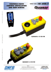
12-CHANNELS RADIO
CONTROL INSTALLATION
AND USER MANUAL
Codice foglio: 997-101-50326 Rev: AD
Data: Venerdì 10 giugno 2011
Codice fascicolo: 997-101-50330 Rev: AD
FAMILY CODE
pag.3
O.M.F.B. S.p.A. Hydraulic Components
We reserve the right to make any changes without notice.
Edition 2005.06 No reproduction, however partial, is permitted.
Via Cave, 7/9 25050 Provaglio d’Iseo (Brescia) Italy Tel.: +39.030.9830611
Fax: +39.030.9839207-208 Internet:www.omfb.it e-mail:[email protected]
101-050-7
USER MANUAL
101-050-7
1.1 Product Markings and certification .......................................................... pag. 5
1.2 New safety feature ................................................................................ pag. 7
1.3 OMFB QUASAR Radio remote control systems ........................................ pag. 7
1.4 QUASAR 12-channel receveir ................................................................. pag. 7
1.5 QUASAR transmitter .............................................................................. pag. 8
2. INSTALLATION AND MECHANICAL FASTENING OF THE RECEVEIR ...pag. 9
2.1 General comments ................................................................................ pag. 9
2.2 Positioning the receveir .......................................................................... pag. 9
2.3 Fastening the receveir ............................................................................ pag. 9
2.4 Insertion in additional housings .............................................................. pag. 10
2.5 Electric connection ................................................................................ pag. 10
2.6 Level of protection of receiver and important Notes for wiring assembly .... pag. 10
Codice fascicolo: 997-101-50330 Rev: AD
1. GENERAL COMMENTS .....................................................................pag. 5
3. TECHNICAL
4. ELECTRICAL
SPECIFICATIONS ..........................................................pag. 11
4.1. Electrical specification of the admissible loads ......................................... pag. 11
4.2 Connecting devices to the receiver ......................................................... pag. 12
5. EMERGENCY
STOP ..........................................................................pag. 13
5.1 Emergency Stop engaged by the Transmitter............................................ pag. 13
5.2 Emergency Stop engaged by the Receiver ............................................... pag. 13
Data: Venerdì 10 giugno 2011
SPECIFICATIONS ..........................................................pag. 11
3.1. QUASAR transmitter apparatus .............................................................. pag. 11
3.2. QUASAR Receveir apparatus ................................................................ pag. 11
THE SYSTEM ........................................................................pag. 13
6.1 Using the transmitter .............................................................................. pag. 13
6.2 Programming procedure ........................................................................ pag. 14
6.3 Reset after emergency ........................................................................... pag. 14
6.4 Motor auxiliary...................................................................................... pag. 14
7. FREQUENTLY
ASKED QUESTIONS ....................................................pag. 15
pag.4
O.M.F.B. S.p.A. Hydraulic Components
We reserve the right to make any changes without notice.
Edition 2005.06 No reproduction, however partial, is permitted.
Via Cave, 7/9 25050 Provaglio d’Iseo (Brescia) Italy Tel.: +39.030.9830611
Fax: +39.030.9839207-208 Internet:www.omfb.it e-mail:[email protected]
Codice foglio: 997-101-50326 Rev: AD
6. USING
USER MANUAL
1. GENERAL
101-050-7
COMMENTS
Codice fascicolo: 997-101-50330 Rev: AD
1.1 Product Markings and certification
QUASAR radio remote controls meets the rules set forth in the following harmonised
technical standards:
• EN 300 220 - 3:2000 for Effective Use of Spectrum;
• EN 301 489 - 3:2000 for Electromagnetic Compatibility;
• EN 60950:2000 (3rd EDITION) for the Protection of the health and the safety of
the user.
Compliance with the above technical standards, certified by test reports issued by the
competent European body IMQ S.p.A. (via Quintiliano, 43 I-20138 Milano), grants the
presumption of conformity to QUASAR radio remote controls with the essential
requirements and other provisions set forth in European Directives:
• RTTE n° 99/05/CE, D. Lgs. n° 269 del 09/05/01
• EMC n° 89/336/CE, articles 4, 10.1 and 10.2, annexes I and II
• Bassa Tensione n° 73/23/CE, article 2, annexes I, III part 8 and IV and subsequent
modifications.
Codice foglio: 997-101-50326 Rev: AD
Data: Venerdì 10 giugno 2011
Compliance with pertinent directives is certified by the presence of the CE Marking on the
product:
The compliance of QUASAR radio remote controls with essential requirements of
Directive 99/05/EC allows them to be placed on the market, put into service and
have the right to be connected in every European country, as well as all countries
belonging to CEPT, without the need for homologation by the relevant Postal and
Telecommunications Administration.
According to an indicative and non-exhaustive list of equipment that falls within the
classification established by European Commission Decision 2000/299/EC, QUASAR
radio remote controls are not subject to any restrictions for installation and connection,
since they belong to a class of S.R.D. (Short Range Devices) without specific uses and
operating within a radio frequency band (433.050 – 434.790 MHz) harmonized within the
European Community.
The QUASAR radio remote control receiver also complies with the essential
requirements and other provisions set forth in European Directive 95/54/EC
and in ECE/ONU Regulation No 10 Addendum 2, relating to “Suppression of radio
interference (Electromagnetic Compatibility) produced by spark-ignition engines fitted to
motor vehicles”.
Concerning to Electromagnetic Compatibility 95/54/EC is the reference directive
for every electrical/electronic system included in road vehicles because it constitutes a
“specific directive” for the purposes of Article 2, par. 2, of Council Directive 89/336/EC,
effective beginning 1 January 1996.
pag.5
O.M.F.B. S.p.A. Hydraulic Components
We reserve the right to make any changes without notice.
Edition 2005.06 No reproduction, however partial, is permitted.
Via Cave, 7/9 25050 Provaglio d’Iseo (Brescia) Italy Tel.: +39.030.9830611
Fax: +39.030.9839207-208 Internet:www.omfb.it e-mail:[email protected]
USER MANUAL
The provisions of 95/54/EC must be satisfied, concerning Electromagnetic Compatibility,
by all vehicles as defined in Directive 70/156/EC relating to the type-approval of motor
vehicles and their trailers, as emended by 92/53/EC, as well as their components or
separate technical units that are exempt from the compliance with the rules of 89/336/
EC.
Conformity tests prescribed by Directive 95/54/CE and ECE/ONU Reg. No 10 Add. 9 were
carried out at the laboratory IMQ S.p.A. (via Quintiliano, 43 I-20138 Milano).
Compliance of QUASAR radio remote controls with Dir. 95/54/EC requirements is certified
by the Notified Body NSAI by releasing the approval number for the product marking:
e24*72/245*95/54*1107*00.
Compliance is shown by product marking:
e24
Codice fascicolo: 997-101-50330 Rev: AD
101-050-7
021107
10R
02 0185
Codice foglio: 997-101-50326 Rev: AD
E24
Data: Venerdì 10 giugno 2011
Compliance of QUASAR radio remote controls with the ECE/ONU Reg. No 10 Add. 9
requirements is certified by the Notified Body NSAI by releasing the approval number
for the product marking:
E24 10R-020185.
Compliance is shown by product marking:
pag.6
O.M.F.B. S.p.A. Hydraulic Components
We reserve the right to make any changes without notice.
Edition 2005.06 No reproduction, however partial, is permitted.
Via Cave, 7/9 25050 Provaglio d’Iseo (Brescia) Italy Tel.: +39.030.9830611
Fax: +39.030.9839207-208 Internet:www.omfb.it e-mail:[email protected]
USER MANUAL
101-050-7
Codice fascicolo: 997-101-50330 Rev: AD
1.2 New safety feature
20 minutes after the last actuation the receiver automatically switch-off.
For restarting operations you may EITHER “press the recevier green button” OR
“press and maintaining pressed one of the transmitter button for at least 2 second
and release it”.
1.3 OMFB QUASAR Radio remote control systems
The radio remote control system consists of the following components:
• 1 receiver:
1. 12-channel receiver (12 CH)
• 1 transmitter:
1. QUASAR transmitter (to control 2- to 12-channel systems)
Data: Venerdì 10 giugno 2011
1.4 QUASAR 12-channel receveir
Emergency
Button
Start Button
Receiver status light
Codice foglio: 997-101-50326 Rev: AD
Acc/dec/control button
Buzzer 95 dB
pag.7
O.M.F.B. S.p.A. Hydraulic Components
We reserve the right to make any changes without notice.
Edition 2005.06 No reproduction, however partial, is permitted.
Via Cave, 7/9 25050 Provaglio d’Iseo (Brescia) Italy Tel.: +39.030.9830611
Fax: +39.030.9839207-208 Internet:www.omfb.it e-mail:[email protected]
USER MANUAL
101-050-7
1.5 QUASAR transmitter
Codice fascicolo: 997-101-50330 Rev: AD
To control configurations with 2, 2+2, 4, 6, 8, 10, and 12 channels.
Function buttons
Transmission active
Start and backlight
activation button
Battery charger
status
Data: Venerdì 10 giugno 2011
Battery charger
connection
Emergency button
pag.8
O.M.F.B. S.p.A. Hydraulic Components
We reserve the right to make any changes without notice.
Edition 2005.06 No reproduction, however partial, is permitted.
Via Cave, 7/9 25050 Provaglio d’Iseo (Brescia) Italy Tel.: +39.030.9830611
Fax: +39.030.9839207-208 Internet:www.omfb.it e-mail:[email protected]
Codice foglio: 997-101-50326 Rev: AD
Status signal 24/36
USER MANUAL
101-050-7
2. INSTALLATION AND MECHANICAL FASTENING OF THE RECEIVER
Codice fascicolo: 997-101-50330 Rev: AD
2.1 General comments
The receiver must be installed using the 2 screws already present on the receiver,
and must not be opened or drilled for any reason. For applications involving strong
vibrations, it is recommended to insert the appropriate anti-vibration material
between the external housing of the receiver and the support to which it is fastened.
Any opening, drilling or similar operations on the receiver not previously agreed
upon with OMFB will void the product warranty.
The following factors must be taken into consideration when choosing the receiver position
on the vehicle:
• The red mushroom-head Emergency Stop button must be easily accessible;
• The best reception capacity is obtained by placing the receiver as high as possible
off the ground;
• Whenever possible, the receiver should be clearly visible from the transmitter
work area.
• The field radiates concentrically from the antenna; in the case of receivers without
external antenna, the latter is aligned with the receiver box.
Codice foglio: 997-101-50326 Rev: AD
Data: Venerdì 10 giugno 2011
2.2 Positioning the receiver
Install the receiver with the cable input facing down, never upwards.
TOP
UPPER SIDE
2.3 Fastening the receiver
To fasten the receiver you must take advantage of the prigionieri already present on the
receiver box. Do not drill any holes in the box, under penalty of voiding the product
warranty.
pag.9
O.M.F.B. S.p.A. Hydraulic Components
We reserve the right to make any changes without notice.
Edition 2005.06 No reproduction, however partial, is permitted.
Via Cave, 7/9 25050 Provaglio d’Iseo (Brescia) Italy Tel.: +39.030.9830611
Fax: +39.030.9839207-208 Internet:www.omfb.it e-mail:[email protected]
USER MANUAL
101-050-7
The receiver may be inserted in an additional housing as long as it is made of plastic
and not metal.
Yes
No
Plastic
Metal
Codice fascicolo: 997-101-50330 Rev: AD
2.4 Insertion in additional housings
Insertion in a metal housing must absolutely be agreed upon and assessed with OMFB
staff to avoid unpleasant malfunctions.
The power supply line (+12/24V batt and ground) should lead to the receiver directly from
the main source (battery or stabilized power source), with cables adequately sized for the
load to be carried (cross-section of at least 1 mm^2), also using a safety fuse.
The power supply line to the receiver must be kept locked, or under a switch dedicated
specifically to the radio remote control system, or under an appropriately sized battery
disconnector.
It is essential that the radio remote control system never be powered while the
vehicle is running: the installer is responsible for informing the system end user
of this fact.
Data: Venerdì 10 giugno 2011
2.5 Electric connection
The product, as supplied by OMFB, is not to be considered IP65 as the product is equipped
with a metre of sheath and wires without tin ending.
The casing of the receiver and the buttons guarantee the IP65 level of protection if the
wiring is connected according to the rules of the trade.
It is the installer’s responsibility to connect the wiring taking all the necessary precautions,
according to the rules of the trade, using suitable derivation boxes and/or sufficiently
suitable isolation systems, in order to guarantee the IP65 level of the complete product.
An incorrect wiring assembly leads to the loss of the level of protection of the receiver.
OMFB categorically passes all responsibility for the wiring of the system onto the final
installer.
pag.10
O.M.F.B. S.p.A. Hydraulic Components
We reserve the right to make any changes without notice.
Edition 2005.06 No reproduction, however partial, is permitted.
Via Cave, 7/9 25050 Provaglio d’Iseo (Brescia) Italy Tel.: +39.030.9830611
Fax: +39.030.9839207-208 Internet:www.omfb.it e-mail:[email protected]
Codice foglio: 997-101-50326 Rev: AD
2.6 Level of protection of receiver and important Notes for wiring
assembly
USER MANUAL
3. TECHNICAL
101-050-7
SPECIFICATIONS
Codice fascicolo: 997-101-50330 Rev: AD
3.1 Transmitter apparatus QUASAR
•
•
•
•
•
Modulation FSK ±20 KHZ
Working frequency: 433,92 MHz+/-75KHz
Power RF E.R.P. a 433,92 MHz: 1÷3 mW
Battery 2x1,2V/NiMh/1,2Ah
Battery recharger 12/24V DC
3.2 Receiver apparatus
SUPPLY VOLTAGE
Codice foglio: 997-101-50326 Rev: AD
Data: Venerdì 10 giugno 2011
MAXIMUM CURRENT CONSUMPTION
MAXIMUM SWITCHABLE CURRENT
WORKING FREQUENCY
RF SENSITIVITY
PASS-BAND
INTERFERENCE REJECTION
RF EMISSION TO ANTENNA
min 9 V, max 28 V
370 mA a 10 V
563 mA a 28 V
8A
433,920 MHz
- 100 dBm
600kHz a - 3dB
- 120 dB
- 80 dBm
IP PROTECTION (EN 60529)
The box and buttons assure IP65
protection level of the wrapping. The
wiring is excluded: its protection level
is assured by the installer
OUTPUTS
CURRENT CARRYING CAPACITY
TEMPERATURA DI FUNZIONAMENTO
N° 12 MOSFET
max 8 A
- 30 / + 80 °C
4. ELECTRICAL
SPECIFICATIONS
4.1 Electrical specifications of the admissible loads
The output stage of radio remote controls uses unstable MOSFET.
The systems are sized for a maximum load of 8 A inductive simultaneously.
The MOSFET are sized to 16 A in any case, the mushroom-head emergency control, or
from the transmitter, cuts off power to the outputs and thus ensures the absolute safety of
the system.
pag.11
O.M.F.B. S.p.A. Hydraulic Components
We reserve the right to make any changes without notice.
Edition 2005.06 No reproduction, however partial, is permitted.
Via Cave, 7/9 25050 Provaglio d’Iseo (Brescia) Italy Tel.: +39.030.9830611
Fax: +39.030.9839207-208 Internet:www.omfb.it e-mail:[email protected]
USER MANUAL
101-050-7
A terminal board is used to connect devices (solenoid valves, remote switches) to the
electronic board of the receiver.
In standard versions the radio remote controls are supplied with 1,50 m of cable,
mounting one connector that is described: the cables used in the standard versions have
a cross-section of 1 mm^2, and the function/color pairing is as follows:
FUNCTION
CE Motor/Valve
1
2
3
4
5
6
7
8
FUNCTION
9
10
11
12
24
36
+12/24V
Earth
CABLE
Blue
Blue1
Blue2
Blue3
Blue4
Blue5
Blue6
Blue7
Blue8
CABLE
Blue9
Blue10
Blue11
Blue12
Yellow
Green
Red
Yellow/Green
Codice fascicolo: 997-101-50330 Rev: AD
4.2 Connecting devices to the receiver
Button DX
Yellow
Violet
Warning alarm
Output stage MOSFET
Yellow/Black
+ Battery 12/24V
Acoustic signal
Emergency button
release
Fuse 20A
Relay emergency
release
Data: Venerdì 10 giugno 2011
Button SX
Green
Pink
Blue 1
Codice foglio: 997-101-50326 Rev: AD
Blue 2
Blue 3
Blue 4
Blue 5
Blue 6
Blue 7
Blue 8
Blue 9
Blue 10
Blue 11
Blue 12
Blue
pag.12
O.M.F.B. S.p.A. Hydraulic Components
We reserve the right to make any changes without notice.
Edition 2005.06 No reproduction, however partial, is permitted.
Via Cave, 7/9 25050 Provaglio d’Iseo (Brescia) Italy Tel.: +39.030.9830611
Fax: +39.030.9839207-208 Internet:www.omfb.it e-mail:[email protected]
USER MANUAL
101-050-7
5. EMERGENCY STOP
Codice fascicolo: 997-101-50330 Rev: AD
5.1 Emergency Stop engaged by the Transmitter
The emergency stop command predominates over all other conditions, and thus may be
activated even if the key for another transmitter function is inserted due to a breakdown
or carelessness.
To deactivate the Emergency Stop function (signaled when the receiver status light goes on
steady) and restore system operation, press the green Reset button.
5.2 Emergency Stop engaged by the Receiver
To activate the Emergency Stop function from the receiver press the mushroom-head STOP
button. The receiver status light remains on steady, indicating receiver emergency status.
To restore system operation, release the push-button by turning it clockwise and press
the green Start button.
Codice foglio: 997-101-50326 Rev: AD
Data: Venerdì 10 giugno 2011
6. USING
THE SYSTEM
6.1 Using the transmitter
When supplied, the transmitter has a minimum battery charge. Therefore, the battery
must first be recharged for approximately 6 hours. This is done by connecting it to the
universal 12V/24V battery charger supplied. The “Bat” light on the transmitter goes on,
and remains on while the transmitter is being charged. It goes off when the unit is fully
charged. To activate the transmitter, press the Start button and check that the “Bat” light
blinks approximately once every 2 seconds, indicating that the transmitter is in Stand-by
mode. If no function is activated, the transmitter turns off automatically after 30 seconds
from the last use. Once the transmitter is ON, to activate the backlight, press the Start
button and keep it pressed for 2 seconds. The backlight turns off temporarily when any
function button is pressed, thus concentrating all available power on the radio emission
and optimizing its use. To disable backlighting, press the Start button once more and keep
it pressed for 2 seconds. Backlighting is also disabled when the transmitter turns off after
being idle for 30 seconds. An increase in the Bat light blink rate (e.g. if the frequency is
1 blink or more a second) means that the batteries are low and need to be recharged.
This is done by connecting the transmitter to the battery charger plugged into the vehicle
12V/24V outlet.
pag.13
O.M.F.B. S.p.A. Hydraulic Components
We reserve the right to make any changes without notice.
Edition 2005.06 No reproduction, however partial, is permitted.
Via Cave, 7/9 25050 Provaglio d’Iseo (Brescia) Italy Tel.: +39.030.9830611
Fax: +39.030.9839207-208 Internet:www.omfb.it e-mail:[email protected]
USER MANUAL
101-050-7
Normally the system is supplied pre-programmed. Therefore the following operations are
only necessary when the transmitter needs to be replaced. The programming procedure
enables the receiver to recognize the transmitter code. To enter the system programming
mode, press the green button on the receiver and keep it pressed for at least 10 seconds.
The status light starts blinking, indicating that you have entered the receiver programming
mode. Once the status light starts blinking, press the green button once more and keep
it pressed for 5 seconds to reset any previously saved codes. Once the receiver has been
set in programming mode (the red light blinking), press the transmitter Start button and
then press any of the function buttons. The light remains on steady for a few instants and
then it goes off, indicating that the transmitter code has been acquired. Once the receiver
has been set in programming mode, if it does not detect any valid code for more than 10
seconds, the system reverts to stand-by mode, keeping the current code.
Codice fascicolo: 997-101-50330 Rev: AD
6.2 Programming procedure:
Start Button
6.3 Reset after emergency:
After a transmitter emergency, the reset can only be performed by pressing the green reset
button on the receiver. The emergency mode is indicated with the receiver status light on
steady.
6.4 Motor Auxiliary:
The Motor Auxiliary output is activated in parallel with each output signal if its Dip-Switch
is set to ON.
pag.14
O.M.F.B. S.p.A. Hydraulic Components
We reserve the right to make any changes without notice.
Edition 2005.06 No reproduction, however partial, is permitted.
Via Cave, 7/9 25050 Provaglio d’Iseo (Brescia) Italy Tel.: +39.030.9830611
Fax: +39.030.9839207-208 Internet:www.omfb.it e-mail:[email protected]
Codice foglio: 997-101-50326 Rev: AD
Data: Venerdì 10 giugno 2011
Receiver
status light
USER MANUAL
101-050-7
Codice foglio: 997-101-50326 Rev: AD
Data: Venerdì 10 giugno 2011
Codice fascicolo: 997-101-50330 Rev: AD
7. FREQUENTLY ASKED QUESTIONS
THE TRANSMITTER
RECEIVER.
IS NOT WORKING, OR WORKS ONLY AT A SHORT DISTANCE FROM THE
THE TRANSMITTER
WAS DROPPED AND NOW IT DOESN’T WORK.
Make sure that:
• The receiver power supply is correct both in terms of voltage (9 - 28 V) and
polarity;
•The red emergency button of the receiver is not pressed, and that you have
pressed the green reset button;
• The receiver is not installed in a metal housing;
• The LED on the transmitter lights when any of the commands is pressed. If not,
make sure that the battery is present and charged, and replace it if necessary.
• The receiver has been programmed correctly. To be certain, repeat the steps
described in the section PROGRAMMING PROCEDURES;
• The controlled devices function correctly if powered directly, cutting out the radio
remote control, and if they have no short-circuits;
Make sure that:
• The transmitter battery is still in its compartment;
• The battery connection is intact and ensures electrical contact;
IS IT POSSIBLE TO OBTAIN CLEAN CONTACTS IN PLACE OF THOSE THAT REFLECT
THE SUPPLY VOLTAGE?
No, you must use additional controlled relays at the supply voltage, and take the desired
clean contact from these.
ONE OF THE LATEX SAFETY HOODS IS TORN.
Send the receiver to OMFB SpA Hydraulic Components to replace and repair it, since the
absence of these protections reduces the IP protection rating of the apparatus.
DOES THE QUASAR RADIO REMOTE CONTROL REQUIRE ANY MAINTENANCE?
The QUASAR radio remote control requires no maintenance aside. However, it is
recommended to keep the receiver clean, especially removing any deposits of mud or
other material that could degrade its performance in the long run. Do not use hydraulic
cleaners.
IS IT POSSIBLE TO INSERT THE RECEIVER INTO AN ADDITIONAL PLASTIC
HOUSING?
Yes, this is not subject to any particular limitations, as long as you are certain that the plastic
of the housing into which the receiver is inserted has a minimal (or no) lead content.
If the problem persists, contact OMFB SpA Hydraulic Components.
pag.15
O.M.F.B. S.p.A. Hydraulic Components
We reserve the right to make any changes without notice.
Edition 2005.06 No reproduction, however partial, is permitted.
Via Cave, 7/9 25050 Provaglio d’Iseo (Brescia) Italy Tel.: +39.030.9830611
Fax: +39.030.9839207-208 Internet:www.omfb.it e-mail:[email protected]