1
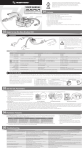
FAMILY CODE
Codice foglio: 997-010-12156 Rev: AE
Data: Mercoledì 13 ottobre 2010
MANUAL FOR
INSTALLATION AND USE
page 1
O.M.F.B. S.p.A. Hydraulic Components
We reserve the right to make any changes without notice.
Edition 2006.07 No reproduction, however partial, is permitted.
Via Cave, 7/9 25050 Provaglio d’Iseo (Brescia) Italy Tel.: +39.030.9830611
Fax: +39.030.9839207-208 Internet:www.omfb.it e-mail:[email protected]
121-053
USER MANUAL
1. INFORMATION PRIOR TO INSTALLATION
121-053
..........................................page 3
1.1 Information about SAFETY ...................................................................... page 3
1.2 Contents of package ............................................................................ page 3
1.3 Equipment for installation ....................................................................... page 4
1.4 Electric/Pneumatic specifications ............................................................ page 4
1.5 Product marking ................................................................................... page 5
1.6 Versions available.................................................................................. page 6
2.
INSTALLATION ..................................................................................page 8
2.1 Introduction........................................................................................... page 8
2.2 Mechanical installation .......................................................................... page 8
2.3 Pneumatic connections .......................................................................... page 10
2.4 Electric connections ............................................................................... page 12
3.1 Test of signals ....................................................................................... page 14
3.2 Test of controls ...................................................................................... page 14
3.3 P.T.O. ................................................................................................... page 14
3.4 Tip control ............................................................................................ page 15
3.5 Low control ........................................................................................... page 16
3.6 Control of tractor/crane selector ............................................................. page 17
3.7 Tipper’s manual control.......................................................................... page 17
3.8 Setting the speed of slow lowering (121-053-02008) ............................... page 18
3.9 Block of rear door (121-053-02017) ....................................................... page 19
3.10 Auxiliary side doors and tarpaulin system controls (121-053-02017) ........ page 20
3.11 Hydraulic unit remote switch (121-053-02017) ....................................... page 20
3.12 Firmware setup (121-053-02017) .......................................................... page 21
4.
TECHNICAL FEATURES OF PRODUCT .................................................page 22
4.1 Pneumatic diagram.............................................................................................page 22
4.2 Wiring diagram...................................................................................................page 23
page 2
O.M.F.B. S.p.A. Hydraulic Components
We reserve the right to make any changes without notice.
Edition 2006.07 No reproduction, however partial, is permitted.
Via Cave, 7/9 25050 Provaglio d’Iseo (Brescia) Italy Tel.: +39.030.9830611
Fax: +39.030.9839207-208 Internet:www.omfb.it e-mail:[email protected]
Data: Mercoledì 13 ottobre 2010
TESTING SYSTEM ...............................................................................page 14
Codice foglio: 997-010-12156 Rev: AE
3.
MANUAL FOR INSTALLATION AND USE
1.
121-053
INFORMATION PRIOR TO INSTALLATION
General information for the product installation.
1.1 Information about SAFETY
The installation should be made only by specialized personnel with adequate training.
During installation it must be taken all the necessary measures and precautions to ensure
the personal safety and that of the people around in the installation zone. In particular, if
the KipTronicEVO2 is installed on a vehicle with tilting platform already installed, a safety
pole must be used.
Electrical and pneumatic connections made during installation of the system must be carried
out in a workmanlike manner using equipment, consumable materials and procedures
that respect the necessary safety standards.
1.2 Content of the package
Codice foglio: 997-010-12156 Rev: AE
Data: Mercoledì 13 ottobre 2010
Before proceeding with installation, make sure the KipTronicEVO2 package contains the
following materials:
Control unit
holder for control unit
Female/female connector RJ54
Box
Instructions for installation and use
Instruction CD
page 3
O.M.F.B. S.p.A. Hydraulic Components
We reserve the right to make any changes without notice.
Edition 2006.07 No reproduction, however partial, is permitted.
Via Cave, 7/9 25050 Provaglio d’Iseo (Brescia) Italy Tel.: +39.030.9830611
Fax: +39.030.9839207-208 Internet:www.omfb.it e-mail:[email protected]
USER MANUAL
121-053
1.3 Equipment for installation
Before proceeding with installation make sure you have the following tools and
materials:
• 6 mm plastic hose
• Pipe cutter (NOTE: pipes for pneumatic uses must be cut with a special tool otherwise
the pneumatic circuit may lead due to the ovalization caused by cutting the pipes with
other tools)
• Fastening bracket
• Fastening screws
• Plastic clamps
Supply voltage
Current absorbed on Stand-by
Current Absorbed to energize
Input managed:
24V DC
0,5 A
1 solenoid/2 solenoids
12 keys per control unit
5 direct inputs on logic unit
5 solenoids in Box
• Outputs controlled:
3 accessory outputs with a capacity of 1 A
8 accessory outputs with a capacity of 0.5A
•
•
•
•
•
Working pressure
Temperature range
IP Protection (EN 60529)
Dimensions
Weight
MAX 12 bar treated air
-30 +50 (°C)
IP44
219x294 mm
page 4
O.M.F.B. S.p.A. Hydraulic Components
We reserve the right to make any changes without notice.
Edition 2006.07 No reproduction, however partial, is permitted.
Via Cave, 7/9 25050 Provaglio d’Iseo (Brescia) Italy Tel.: +39.030.9830611
Fax: +39.030.9839207-208 Internet:www.omfb.it e-mail:[email protected]
Codice foglio: 997-010-12156 Rev: AE
•
•
•
•
Data: Mercoledì 13 ottobre 2010
1.4 Electric/Pneumatic specifications
MANUAL FOR INSTALLATION AND USE
121-053
Data: Mercoledì 13 ottobre 2010
1.5 Product markings and certification
The electronic KipTronic EVO2 device complies with the essential requisites and other
pertinent provisions of European Directive 2006/28/CE (Ministry Decree of Feb.
20, 1996) and ECE/ONU regulation no. 10 Amendment 9, regarding “Elimination of
radioelectric disturbance (Electromagnetic Compatibility) caused by the controlled ignition
engines of motor vehicles”.
On the subject of Electromagnetic Compatibility, directive 2006/28/CE is the reference
directive for electric/electronic units installed on road vehicles as it is the specific directive
for the purposes of art. 2, para. 2, of directive 89/336/CE enacted as of January 1, 1996.
The requisites of directive 2006/28/CE must be satisfied on the subject of
Electromagnetic Compatibility by all vehicles defined in directive 70/156/CE as regards
approval of motor vehicles and trailers, as last amended by directive 92/53/CE, and
their components or technical parts, which are thus exempt from compliance with the
provisions of directive 89/336/CE.
The conformity tests required by directive 2006/28/CE and regulation ECE/ONU no. 10
Em. 9 were carried out in the PRIMA RICERCA & SVILUPPO (via Campagna,
58 - 22020 Gaggino Faloppio (CO)).
Approval of the electronic KipTronic EVO2 device with the requisites of Dir. 2006/28/CE
is certified by the NSAI (National Standards Authority of Ireland-Glasnevin, Dublin 9,
Ireland (+353-1-80703910)) which has issued the approval number for marking the
product, as follows:
e24*72/245*2006/28*1352
Approval is proven by marking the product:
Codice foglio: 997-010-12156 Rev: AE
e24
031352
Approval of the electronic KipTronic EVO2 device with the requisites of Regulation ECE/
ONU no. 10 Em.9 is certified by the NSAI (National Standards Authority of IrelandGlasnevin, Dublin 9, Ireland (+353-1-80703910)) which has issued the approval number
for marking the product, as follows:
E24 10R-020015
Approval is proven by marking the product:
E24
10R
02 0015
page 5
O.M.F.B. S.p.A. Hydraulic Components
We reserve the right to make any changes without notice.
Edition 2006.07 No reproduction, however partial, is permitted.
Via Cave, 7/9 25050 Provaglio d’Iseo (Brescia) Italy Tel.: +39.030.9830611
Fax: +39.030.9839207-208 Internet:www.omfb.it e-mail:[email protected]
USER MANUAL
121-053
1.6 Versions available
KipTronic EVO2 is available in the following configurations:
TIP AND LOW, SELECTOR FOR CRANE/TRAILER AND TARPAULIN SYSTEM
Codice foglio: 997-010-12156 Rev: AE
121.053.02044
Data: Mercoledì 13 ottobre 2010
121.053.02008
TIP AND LOW WITH LOWERING SPEED REGULATION
page 6
O.M.F.B. S.p.A. Hydraulic Components
We reserve the right to make any changes without notice.
Edition 2006.07 No reproduction, however partial, is permitted.
Via Cave, 7/9 25050 Provaglio d’Iseo (Brescia) Italy Tel.: +39.030.9830611
Fax: +39.030.9839207-208 Internet:www.omfb.it e-mail:[email protected]
MANUAL FOR INSTALLATION AND USE
121-053
121.053.02017
Data: Mercoledì 13 ottobre 2010
LIKE THE CODE 121.053.02008 + HYDRAULIC DOORS CONTROL THROUGH POWER PACK
Codice foglio: 997-010-12156 Rev: AE
121.053.02026/02035
121.053.02026: LIKE THE CODE 121.053.02008+HYDRAULIC DOORS CONTROL BY MEANS OF PNEUMATIC
121.053.02035: LIKE THE CODE 121.053.02008+HYDRAULIC DOORS CONTROL BY MEANS OF ELECTRIC
page 7
O.M.F.B. S.p.A. Hydraulic Components
We reserve the right to make any changes without notice.
Edition 2006.07 No reproduction, however partial, is permitted.
Via Cave, 7/9 25050 Provaglio d’Iseo (Brescia) Italy Tel.: +39.030.9830611
Fax: +39.030.9839207-208 Internet:www.omfb.it e-mail:[email protected]
USER MANUAL
121-053
2. INSTALLATION
This section describes the operations necessary for the installation of KipTronic
EVO2 system
2.1 Introduction
The KipTronicEVO2 system was designed to simplify operations of installation. The only
necessary operations are the fastening of the Box on the chassis, the connection of the
pneumatic circuit and connection of the electric power cable and control unit in the cab. In
this chapter we provide some indications as to how to perform each step.
IMPORTANT: In order to ensure the maximum safety of the installer during these
operations and to optimize the installation time, you should proceed in the
following order:
• Mechanical installation
• Pneumatic connection
• Electric connection
The procedure is described here below, step by step.
Codice foglio: 997-010-12156 Rev: AE
Mechanical installation consists of the following steps:
• installation of the Box on the vehicle’s chassis.
• positioning of wires including the control cable, the positive power cable (with fuse)
and the negative power cable.
Data: Mercoledì 13 ottobre 2010
2.2 Mechanical installation
page 8
O.M.F.B. S.p.A. Hydraulic Components
We reserve the right to make any changes without notice.
Edition 2006.07 No reproduction, however partial, is permitted.
Via Cave, 7/9 25050 Provaglio d’Iseo (Brescia) Italy Tel.: +39.030.9830611
Fax: +39.030.9839207-208 Internet:www.omfb.it e-mail:[email protected]
MANUAL FOR INSTALLATION AND USE
121-053
Installation of the Box on the vehicle chassis
You must secure the Box in a zone that satisfies all the following requisites:
•
•
•
•
•
REQUIRED orientation for assembly
safety during maintenance
simple use of the tipper’s manual controls
absolute protection from impacts and mechanical stresses
adequate air circulation around Box
Codice foglio: 997-010-12156 Rev: AE
Data: Mercoledì 13 ottobre 2010
Required orientation for assembly: in order to ensure to the Box the degree of protection for
which it was designed, it must be installed according to the given instructions. And only as
shown below. Installation in any other way could cause malfunctioning of the system that would
automatically invalidate the warranty.
Safety during maintenance: The chosen zone must make it easy and safe to perform the
maintenance on the internal parts of the Box. We therefore recommend a place that can be
reached from outside the vehicle, without raising the tipper for maintenance and without having
to remove the Box in order to open the cover and work on the parts inside.
Easy use of the manual platform raising and lowering controls: These controls are inside the
Box. The Box must be mounted as to allow that, in case of breakdown of the KipTronicEVO2, the
operator can easily open the Box and operate the tipper tip and low controls manually from a
safe position.
Absolute protection from impacts and mechanical stresses in general: The Box contains hightech
parts tested to bear the vibrations of the vehicle. However, these parts should be protected against
impacts and mechanical stresses as they could get critically damaged. Moreover, direct impacts
and mechanical stresses to the Box may case the loss of the level of protection with regard to
water and dust and this could cause malfunctioning in the long term of the KipTronicEVO2
control system.
Adequate circulation of air around the Box: The Box contains hightech parts designed and
tested to withstand the temperatures typically found in the zone of the chassis near the vehicle
transmission. It is necessary, however, that enough air circulates around the Box.
page 9
O.M.F.B. S.p.A. Hydraulic Components
We reserve the right to make any changes without notice.
Edition 2006.07 No reproduction, however partial, is permitted.
Via Cave, 7/9 25050 Provaglio d’Iseo (Brescia) Italy Tel.: +39.030.9830611
Fax: +39.030.9839207-208 Internet:www.omfb.it e-mail:[email protected]
USER MANUAL
121-053
Wiring installation
To install the wiring in side the cab, including the telephone cable and the positive and
negative power cables, use the passages provided from the outside to the inside of the cab
which the installer should know and identify.
The head of the wires (the side where the wires and cable protrude) should be handled
with care in order not to damage the cable and wires and especially not to damage the
telephone type plug on the end of the control cable. Once the wiring head is inside the
cab the installer should check that its passage along the chassis, under the cab and inside
the cab will not cause any critical situations (passage far from heat sources) and that the
wires are adequately protected, and not subject to repetitive movements that could cause
breakage or fatigue.
2.3 Pneumatic connection
When making the pneumatic connections use only suitable piping for automotive
applications and cut the pipes with the specific tool (NOTE: pipes for pneumatic uses must
be cut with a special tool otherwise the pneumatic circuit may lead due to the ovalization
caused by cutting the pipes with other tools)
First connect all the pipes to the outputs as shown in the picture and taking care
to use different colors or mark the pipes suitably:
in this way you will reduce the risk of creating risk conditions for the installer due to
improper connection to the outputs of the KipTronicEVO2 system.
The pneumatic outputs to be connected are:
•
•
•
•
power take-off (where controlled by the KipTronicEVO2 system)
tipping control
lowering control
tractor/crane diverter valve
page 10
O.M.F.B. S.p.A. Hydraulic Components
We reserve the right to make any changes without notice.
Edition 2006.07 No reproduction, however partial, is permitted.
Via Cave, 7/9 25050 Provaglio d’Iseo (Brescia) Italy Tel.: +39.030.9830611
Fax: +39.030.9839207-208 Internet:www.omfb.it e-mail:[email protected]
Codice foglio: 997-010-12156 Rev: AE
IMPORTANT: The pneumatic circuit of the KipTronicEVO2 system is designed
for a maximum working pressure of 12 bar. Higher working pressures can
damage the system, cause malfunctioning or create risks for persons and
property. Before connecting the KipTronicEVO2 to the pneumatic pressure
line, check with a pressure gauge that the pressure does not exceed 12 bar:
if so, the installer is responsible for installing a pressure reducer on the
pneumatic circuit.
Data: Mercoledì 13 ottobre 2010
IMPORTANT: The installer is responsible for ensuring safe working conditions
in this stage. In particular, before making the pneumatic connections, make
sure the safety pole has been properly installed under the platform.
MANUAL FOR INSTALLATION AND USE
121-053
C
A
C
D
E
Data: Mercoledì 13 ottobre 2010
AB
Codice foglio: 997-010-12156 Rev: AE
E
D
A
lowering control
C
tipping control
D
selector
E
power take-off socket
page 11
O.M.F.B. S.p.A. Hydraulic Components
We reserve the right to make any changes without notice.
Edition 2006.07 No reproduction, however partial, is permitted.
Via Cave, 7/9 25050 Provaglio d’Iseo (Brescia) Italy Tel.: +39.030.9830611
Fax: +39.030.9839207-208 Internet:www.omfb.it e-mail:[email protected]
USER MANUAL
121-053
When all the pipes are connected to the outputs, plug them to the air fittings of the Box
respecting the positions shown (see diagram and figure below).
After connecting all the outputs to the Box, connect the pipe on the pneumatic supply line
to the input on the Box and then to the pickup point from the vehicle line.
NOTE: This connection must always be the last one to ensure the maximum safety of the
installer.
A
lowering control
B
IN
C
tipping control
D
selector
E
power take-off socket
AB
C
D
E
IMPORTANT: Electrical installations on vehicles and the connection of external
devices to the original system must be made by expert personnel, under the absolute
and sole responsibility of the person in charge of the job.
IMPORTANT: The installer is responsible for taking all precautions to ensure safe
working conditions in this stage. In particular, before starting to make the electric
connections, make sure a safety support has been properly installed under the
tipper.
Data: Mercoledì 13 ottobre 2010
2.4 Electric connection
• Connection of the wire cableto the sensor that detects the “tipper raised” condition;
• Connection of the control unit to the wire cable in the cab;
• Connection of the electric power line of the locked KipTronicEVO2 system.
“Tipper raised” sensor cable
The KipTronicEVO2 system detects the “tipper raised” condition by closing to mass an input
of the logic unit inside the Box. This information is taken to the input of the logic unit by
the yellow/black wire in the IN “Platform raised sensor” wire.
page 12
O.M.F.B. S.p.A. Hydraulic Components
We reserve the right to make any changes without notice.
Edition 2006.07 No reproduction, however partial, is permitted.
Via Cave, 7/9 25050 Provaglio d’Iseo (Brescia) Italy Tel.: +39.030.9830611
Fax: +39.030.9839207-208 Internet:www.omfb.it e-mail:[email protected]
Codice foglio: 997-010-12156 Rev: AE
Once the pneumatic connection is done, it is possible to proceed with the electrical
connections of the KipTronicEVO2 system. This stage consists of the following steps:
MANUAL FOR INSTALLATION AND USE
121-053
The mass wire is supplied in the same wire, so the installer has to bring these two wires to
a clean contact (Normally closed or open depending on the type of sensor used and the
mode of use).
Control unit in cab
Codice foglio: 997-010-12156 Rev: AE
Data: Mercoledì 13 ottobre 2010
The installation of the control unit in the cab requires connection of the telephone type plug
(situated at the end of the wire cable of the control unit) to the telephone jack on the control cable
coming from the Box: to make this connection use the female/female adapter supplied with the
system.
When making this connection take particular care because any mechanical alteration of the plugs
or adapter could cause malfunctioning of the system or problems after installation.
In particular, after connecting the two plugs to the adapter it is important to prevent any mechanical
action of the crimping of the wire leading to the plugs: it is a good idea to use a wire clamp to
fasten together the coiled wire and the control wire coming from the Box, and a second clamp to
fasten them to the vehicle dashboard.
Connection to the electric power supply
IMPORTANT: The power supply of KipTronic EVO2 system should be taken from a dedicated line
with all following features:
- with a dedicated switch which should be unabled by users when the vehicle is moving on the
road
- protected by a fuse
- positiv under lock and key
It’s body builder’s own responsibility to make sure the respect of the above mentioned conditions,
in order not to lose the warranty on the product.
In case this rule is not respected, the body builder risks to cause damage to person or property and
by not respecting it he assumes the whole responsibility of his choice.
IMPORTANT: Connection of the power supply must be made with the vehicle off and the battery
disconnection switch must also be off, if possible.
The positive pole of the electric power supply must be connected by a fuse to a locked positive
pole of the vehicle: the connection must be made in a “workmanlike manner” using suitable
consumable materials for the application of the vehicle.
The negative pole must be connected to a mass point on the vehicle and not to the chassis or other
points where “connection to mass is only presumed or random”.
page 13
O.M.F.B. S.p.A. Hydraulic Components
We reserve the right to make any changes without notice.
Edition 2006.07 No reproduction, however partial, is permitted.
Via Cave, 7/9 25050 Provaglio d’Iseo (Brescia) Italy Tel.: +39.030.9830611
Fax: +39.030.9839207-208 Internet:www.omfb.it e-mail:[email protected]
USER MANUAL
121-053
3. TESTING OF THE SYSTEM
This chapter describes the procedures for testing the system after installation.
3.1 Testing signals
After the installation is complete, it is important to test, first of all, the function of the
signals: tipper raised, doors open...
To test the signals proceed as follows.
Platform raised: create the “tipper raised” condition on the sensor used (switching the limit
switch or causing overpressure on the pressure switch...) and check for the yellow light on
the control unit and the 95 dB acoustic signal on the Box.......
3.2 Test of controls
After testing the signals, check the operation of each control as follows.
When the red PTO led is on, and the PTO key is pressed and released (with the clutch
depressed) the red PTO light should be off and the Box should receive the command to
disengage the PTO and react by de-energizing the PTO control solenoid on the solenoid
panel in the Box and stop pressure to its output towards the power take-off.
page 14
O.M.F.B. S.p.A. Hydraulic Components
We reserve the right to make any changes without notice.
Edition 2006.07 No reproduction, however partial, is permitted.
Via Cave, 7/9 25050 Provaglio d’Iseo (Brescia) Italy Tel.: +39.030.9830611
Fax: +39.030.9839207-208 Internet:www.omfb.it e-mail:[email protected]
Codice foglio: 997-010-12156 Rev: AE
For vehicles on which the controls of the power takeoff is handled by the KipTronic EVO2 (it means only
where a pneumatic connection is installed between
the Box and the P.T.O., so that this function will not
be used, for example, on vehicles with original
P.T.O.) the engagement and disengagement are
activated by pressing the “PTO” key.
NOTE: Before pressing the “PTO” the operator
must press and hold the clutch; this is valid for to the
engagement stage, with the red LED off, and the disengagement
stage with the red LED
on. When the KipTronicEVO2 controls engagement of the PTO,
the condition of “PTO engagement control on” is signaled to the
operator by the red led which is “on” with steady light on the control
unit and marked “PTO”.
When the PTO button is pressed (with the clutch pressed) and the red
PTO light is off, the red “PTO” light should come “on” and the control
to engage the PTO is sent to the Box which reacts by energizing the
PTO control solenoid, present on the solenoid panel in the Box with
pressure from its output towards the PTO.
Data: Mercoledì 13 ottobre 2010
3.3 Power take-off control
MANUAL FOR INSTALLATION AND USE
121-053
3.4 Tip control
IMPORTANT: The operator is responsible for ascertaining that the tests do
not involve any risk for persons or property in the operations area.
In compliance with the regulations in force, the tip
control, like all the controls that move the tipper,
is configured as a “deadman” control: movement
starts when the operator presses the tip key and
continues as long as the key is pressed. The instant
the operator released the key the tip, or low, stops.
If not , the system should be checked to find the cause of the
malfunction (for example, error in electrical or pneumatic
connections): if the problem persists contact OMFB for further
instructions.
When the tipper is starts raising from the rest position, this is
signaled by the yellow LED on the Tipper control and by the 95 dB
acoustic signal on the Box.
If this does not happen, check the electric connection on the sensor that detects the raised
platform conditions (“rat-tail” limit switch, pressure switch...) by shortcircuiting the brown
and yellow/black wires, the yellow LED and 95 dB acoustic signal should witch on if they
are not present, contact OMFB.
IMPORTANT: It is also important to test the emergency function: with the
low control in use (the tipper is lowering), the turning off the ignition key
of the vehicle must stop the descent. If not, make sure the power supply
of the KipTronicEVO2 system is correctly taken from the locked system as
required. If not, there is no emergency stop control.
Codice foglio: 997-010-12156 Rev: AE
Data: Mercoledì 13 ottobre 2010
IMPORTANT: It is essential to verify that the ascent
movement stops immediately upon releasing the key.
page 15
O.M.F.B. S.p.A. Hydraulic Components
We reserve the right to make any changes without notice.
Edition 2006.07 No reproduction, however partial, is permitted.
Via Cave, 7/9 25050 Provaglio d’Iseo (Brescia) Italy Tel.: +39.030.9830611
Fax: +39.030.9839207-208 Internet:www.omfb.it e-mail:[email protected]
USER MANUAL
121-053
If not the system should be checked to find the cause of the malfunction (for example,
error in electrical or pneumatic connections): if the problem persists contact OMFB for
further instructions.
IMPORTANT: It is also important to test the emergency function: with the low
control in use (the tipper is lowering), the turning off the ignition key of the vehicle
must stop the descent. If not, make sure the power supply of the KipTronicEVO2
system is correctly taken from the locked system as required. If not, there is no
emergency stop control.
page 16
O.M.F.B. S.p.A. Hydraulic Components
We reserve the right to make any changes without notice.
Edition 2006.07 No reproduction, however partial, is permitted.
Via Cave, 7/9 25050 Provaglio d’Iseo (Brescia) Italy Tel.: +39.030.9830611
Fax: +39.030.9839207-208 Internet:www.omfb.it e-mail:[email protected]
Codice foglio: 997-010-12156 Rev: AE
The KipTronicEVO2 has two separate lowering controls: fast low
and slow low. The fast lowering control lowers the tipper at top
speed, opening the oil passage completely from the cylinder to
the drain. The slow lowering control causes descent at
slower speed by opening the passage only partially
for the oil from the cylinder to the drain: slow
descent speed varies depending on the weight of
the tipper (tipper with aluminum doors descent
more slowly than platforms in steel), depending on
the size of the hydraulic system (single front cylinder
systems descent more rapidly than those with double
cylinder..., systems with tipping valves with high
capacity such as 150-200 l/min, can partialize better
than valves with lower capacity,
such as 80 l/min); also, slow descent speed is affected by the
air line pressure of the vehicle (because the partialization of
the opening is achieved by controlling the opening times of the
descent control solenoids and not the pressure in the pneumatic cylinder of the tipping
valve).
IMPORTANT: The operator is responsible for ascertaining that the testing
operations do not cause risks for any persons or property in the area operations.
In compliance with the regulations in force, the rapid and slow lowering controls, like all
the controls that move the tipper, are configured as “deadman controls”: movement starts
when the operator presses the key and continues only as long as the key is pressed and
only stops when it is released.
IMPORTANT: It is essential to verify that the descent movement stops immediately
upon releasing the key.
Data: Mercoledì 13 ottobre 2010
3.5 Descent control
MANUAL FOR INSTALLATION AND USE
121-053
3.6 Control of tractor/crane selector
When it is prearranged in the hydraulic and pneumatic
system, the tractor/crane selector is controlled by
pressing and releasing the AUX key.
The confirmation of “Switch command sent” is given
by the green LED marked Trailer, which lights up on
the control panel. Pressing and releasing the AUX button
with the green LED “off” send the switch command to the control
and energizes the specific solenoid in the Box so that air pressure is
sent to the selector: with the increase in the pressure of the air line
the switch changes position and changes the direction of the oil from
the main channel to the secondary channel. Pressing and releasing
the AUX key with the green led “on” cancels the switch command,
de-energizes the solenoidin the Box and stop air pressure to the
switch.
Codice foglio: 997-010-12156 Rev: AE
Data: Mercoledì 13 ottobre 2010
3.7 Tipper’s manual movement controls
The KipTronicEVO2 system is also equipped with
manual controls for the following actions: PTO
engagement (if this is controlled by the KipTronic
EVO2), tip control, low control and Auxiliary
control (tractor/trailer selector or other).
The use of the tipper’s manual movement
controls is restricted to skilled operators: the
installer is responsible for training the end
user in their use. The operator is responsible
for checking that these controls are not used
accidentally by extraneous persons. The use of
the manual controls for movement of the tipper should be limited to emergency situations
when the electronic control system is out of order: they enable the operator to complete
maneuvers in progress (tip and empty the tipper, lower the tipper after raising it). To ensure
the necessary safety, in case of any malfunction the operator should use the manual
controls to restore safe conditions for travelling on the road and should then have the
vehicle checked by specialized personnel.
To use these controls it is necessary to open the cover on the Box, identify the solenoid
panel and turn the knobs on the panel to energize them manually.
Every solenoid can be turned to the limit to enable or disable the output connected to it.
page 17
O.M.F.B. S.p.A. Hydraulic Components
We reserve the right to make any changes without notice.
Edition 2006.07 No reproduction, however partial, is permitted.
Via Cave, 7/9 25050 Provaglio d’Iseo (Brescia) Italy Tel.: +39.030.9830611
Fax: +39.030.9839207-208 Internet:www.omfb.it e-mail:[email protected]
USER MANUAL
121-053
IMPORTANT: All manual controls are active only when held. When enabled, they
must be disabled by the operator otherwise the function remains enabled
The installer is responsible for installing the Box in a position where it can be easily
and safely used by the operator. The installer is also responsible for instructing the user
adequately on the use of these controls. The manual controls for moving the tipper only
apply air pressure to the outputs (PTO engagement, tip/low tipping valve, tractor/trailer
selector): the manual controls serve only in case of malfunctions of the KipTronicEVO2
control system and do not permit movement when the problem is relative to the outputs
(for example, it will not be possible to move the tipper with the manual controls if the
tipping valve stem is blocked...).
Special functions
“NOTE: The functions indicated and described here are implemented only
on the codes indicated alongside each.”
The KipTronic EVO 2 system can be configured in part by the installer.
“In particular, as the lowering speed of the tipper depends on the construction features
of the truck and hydraulic system, the speed of slow lowering is generally calibrated at a
moderate speed which can be set by the installer. Small tipper’s or lightweight materials,
or low capacity valves may require an increase in the settings with respect to the standard,
while heavy tipper’s with high capacity valves require a reduction of the settings. To make
these settings, it is necessary to access the firmware settings as described below”.
page 18
O.M.F.B. S.p.A. Hydraulic Components
We reserve the right to make any changes without notice.
Edition 2006.07 No reproduction, however partial, is permitted.
Via Cave, 7/9 25050 Provaglio d’Iseo (Brescia) Italy Tel.: +39.030.9830611
Fax: +39.030.9839207-208 Internet:www.omfb.it e-mail:[email protected]
Codice foglio: 997-010-12156 Rev: AE
Data: Mercoledì 13 ottobre 2010
3.8 Setting the speed of slow lowering (121.053.02008)
MANUAL FOR INSTALLATION AND USE
121-053
To access the firmware configuration mode press the red ENABLE key with the KipTronic off, and
hold it pressed while switching on.
Configuration mode is signaled by the 3 leds lighting up: the red PTO led, the yellow
tipper led and the green trailer led.
To increase by 1 unit the number of impulses of slow low, press the tip key: the led AUX1 will
blink twice. To decrease by 1unit the number of impulses of slow descent, press the slow
low key: the LED AUX1 will immediately blink four times. To increase or decrease further
the number of impulses press the tip or low key and wait every time for the LED AUX1 to
blink 2 or 4 times. NOTE: the system is supplied with a medium number of impulses: 5; for
very light tipper we recommend increasing by 2-3 to a total of 7-8 impulses and for very
heavy tipper we recommend reducing by 1-2 to 3-4 impulses. After making the necessary
settings to exit the configuration mode press the PTO key, and the 3 leds will go out, then
all 5 leds will light up for 1 sec and the system is ready to operate
Codice foglio: 997-010-12156 Rev: AE
Data: Mercoledì 13 ottobre 2010
3.9 Block of rear door (121.053.02017)
The Intentional block of the rear door is possible with
the fixed discharge of the distributor. This can only be
enabled after the two following conditions have been
satisfied:
• the tipper must be in the rest position, or the end of
stroke must detect that the tipper is down
• the operator must hold the red Enable key pressed
for at least 1 second.
When the rear door block is enabled, this is signaled
to the operator by the two red LEDS AUX 1 and AUX
2 blinking.
The installer is responsible for explaining to the
user that the vehicle can travel on the roads only
when these LEDs are enabled and blinking
The operator can move the tipper only after releasing the rear door, by pressing the red key
again for at least 1 sec.
When the operator stops the vehicle, the system memorizes the status in which the operator
left the system with regard to the rear door block, so that when the vehicle is started again
the system returns automatically to the off condition, or to the on condition if the block was
left on, or disabled if it was left disabled.
page 19
O.M.F.B. S.p.A. Hydraulic Components
We reserve the right to make any changes without notice.
Edition 2006.07 No reproduction, however partial, is permitted.
Via Cave, 7/9 25050 Provaglio d’Iseo (Brescia) Italy Tel.: +39.030.9830611
Fax: +39.030.9839207-208 Internet:www.omfb.it e-mail:[email protected]
USER MANUAL
121-053
3.10 Auxiliary side doors and tarpaulin system controls (121.053.02017)
3.11 Hydraulic unit remote switch (121.053.02017)
Codice foglio: 997-010-12156 Rev: AE
This unit is in function when the red LED marked AUX2 is on: when on, it means that the
hydraulic motor is working.
The red LED marked AUX2 should light up only when the operator holds one of the side
doors control keys pressed.
Data: Mercoledì 13 ottobre 2010
The auxiliary controls must be enabled by the
operator by pressing the AUX key: when enabled this
is signaled to the operator by the green “TRAILER”
LED lighting up. As long as the green “TRAILER”
LED is on, the operator can control the two side
doors and the tarpaulin system of the tipper.
The installer is responsible for explaining to the
user that when the green “TRAILER” led is on,
pressing any key relative to control of the side
doors and movement of the tarpaulin will enable
these functions.
The user is solely responsible for ascertaining that
there are no persons or property in the area of
movement of the sidewalls.
Opening at least one of the two side doors is
signaled by the red LED marked AUX1.
page 20
O.M.F.B. S.p.A. Hydraulic Components
We reserve the right to make any changes without notice.
Edition 2006.07 No reproduction, however partial, is permitted.
Via Cave, 7/9 25050 Provaglio d’Iseo (Brescia) Italy Tel.: +39.030.9830611
Fax: +39.030.9839207-208 Internet:www.omfb.it e-mail:[email protected]
MANUAL FOR INSTALLATION AND USE
121-053
Codice foglio: 997-010-12156 Rev: AE
Data: Mercoledì 13 ottobre 2010
3.12 Firmware settings(121.053.02017)
The KipTronic EVO 2 system is partly configurable by the installer.
Configuration mode is signaled by the 3 leds lighting up: the red PTO led, the yellow tipper
led and the green trailer led. When in “configuration mode”, press the tip control so that
the LED AUX1 blinks twice to indicate that use of the keys for control of the rear door has
been enabled to control the rear bike safety device while pressing the slow descent key
will be followed by the red AUX1 key blinking 4 times to indicate control of the tarpaulin
system. After making the necessary settings, exit the configuration mode by pressing the
PTO key. At this point the 3 leds will go off, and all 5 leds will light up for 1 sec and the
system is ready to operate.
In the configuration for control of the rear bike safety door, the two keys serve to raise and
lower the part, controlling in ON/OFF mode (one key for “on” and the other for “off”) one
of the two wires of the roof control cable.
For the regulation of slow lowering speed, once entered in the programming, to increase
of 1 unit the number of slow lowering impulses, press the slow lowering button: the LED
AUX1 will flash twice.
Proceed in this way, to increase the number of impulses from 1 until a maximum of 10.
Once reached the number of 10, a further pression of slow lowering button, will make the
impulse count start again from 1 on.
page 21
O.M.F.B. S.p.A. Hydraulic Components
We reserve the right to make any changes without notice.
Edition 2006.07 No reproduction, however partial, is permitted.
Via Cave, 7/9 25050 Provaglio d’Iseo (Brescia) Italy Tel.: +39.030.9830611
Fax: +39.030.9839207-208 Internet:www.omfb.it e-mail:[email protected]
USER MANUAL
121-053
4. TECHNICAL FEATURES OF PRODUCT
This section analyzes the main technical features of the product with particular reference
to the pneumatic and electric diagrams.
page 22
O.M.F.B. S.p.A. Hydraulic Components
We reserve the right to make any changes without notice.
Edition 2006.07 No reproduction, however partial, is permitted.
Via Cave, 7/9 25050 Provaglio d’Iseo (Brescia) Italy Tel.: +39.030.9830611
Fax: +39.030.9839207-208 Internet:www.omfb.it e-mail:[email protected]
Data: Mercoledì 13 ottobre 2010
Codice foglio: 997-010-12156 Rev: AE
!IRLINE
0-AXBAR
04/%NGAGEMENT
4RUCK#RAVE
4RUCK4RAILER
3ELECTOR
0NEUMATICTIPPINGVALVE
4.1Pneumatic diagram
MANUAL FOR INSTALLATION AND USE
121-053
4.2 Wiring diagram
121-053-02008/02044
"LACK
2ED
"ROWN
&USE!
2ED
&USE!
2ED
&USE!
2ED
"ROWN
9ELLOW"LACK
h4IPPERRAISEDv
3ENSOR
"ATTERY
-ASS
&USE!
h$OORBLOKEDvSIGNAL
Codice foglio: 997-010-12156 Rev: AE
Data: Mercoledì 13 ottobre 2010
4RUCK4RAILER
04/
4IP
,OW
,OW
"LUE"LACK
0INK
3KYBLUE
6IOLET
'REEN
'REEN
6IOLET
3KYBLUE
0INK
"LUE"LACK
9ELLOW"LACK
page 23
O.M.F.B. S.p.A. Hydraulic Components
We reserve the right to make any changes without notice.
Edition 2006.07 No reproduction, however partial, is permitted.
Via Cave, 7/9 25050 Provaglio d’Iseo (Brescia) Italy Tel.: +39.030.9830611
Fax: +39.030.9839207-208 Internet:www.omfb.it e-mail:[email protected]
We reserve the right to make any changes without notice.
Edition 2006.07 No reproduction, however partial, is permitted.
Via Cave, 7/9 25050 Provaglio d’Iseo (Brescia) Italy Tel.: +39.030.9830611
Fax: +39.030.9839207-208 Internet:www.omfb.it e-mail:[email protected]
"ROWN
2ED
"LACK
'REEN
6IOLET
3KY"LUE
0INK
"LUE"LACK
9ELLOW"LACK
7HITE'REEN
"LUE"LACK
0INK
3KYBLUE
6IOLET
'REEN
4RUCK4RAIL
0INK
3KYBLUE
6IOLET
'REEN
page 24
&USE!
2ED &USE!
"LUE
Codice foglio: 997-010-12156 Rev: AE
h$OOR"LOCKEDv3ENSOR
7HITE
7HITE
7HITE
7HITE
7HITE
7HITE
7HITE
&USE!
2ED
/RANGE7HITE
"ROWN
9ELLO"LACK
h4IPPERRAISEDv
3ENSOR
&USE!
2ED
-ASS
O.M.F.B. S.p.A. Hydraulic Components
"ATTERY
7HITE
7HITE
7HITE
7HITE
7HITE
7HITE
7HITE
"ROWN
/PEN4ARPAULIN
&USE!
"LUE
#LOSE4ARPAULIN
2ELAYPROTECTION
2ED
/RANGE
Data: Mercoledì 13 ottobre 2010
,EFTDOORENDOFSTROKE
2IGHTDOORENDOFSTROKE
"ROWN
/RANGE7HITE
7HITE'REEN
"LUE
"LUE
"LUE
"LUE
3OLENOID
2IGHTDOOR
50,EFT2EAR
$7,EFT2EAR
502IGHT
$72IGHT
-ASS
h!CTIVATEDMOTORv3ENSOR
3OLENOID
LEFTDOOR
#ENTRALUNIT
ROCKERSWITCH
USER MANUAL
121-053
121-053-02017