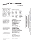
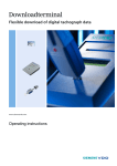
1
2400 User Manual
1
Copyright © 2004 Stoneridge Electronics Ltd
USER HANDBOOK
IMPORTANT
INFORMATION
Dirt ingress can lead to premature failure of the tachograph. Ensure that the device is closed at all times, except when fitting or removing
charts. Do not leave the same paper charts in the tachograph for extended periods of time. There is a probability that eventually the styli
will cut through the paper chart, causing irreparable damage to the tachograph if the vehicle is driven in this condition. Irrespective of the
dangers of causing damage to the tachograph, there is also a legal obligation to remove the charts after 24 hours of use.
Disconnect the electrical supply to the tachograph if:
•
Electrical welding is carried out on the vehicle.
•
Prolonged boost starting is anticipated.
High-level transient voltage can cause permanent damage to the tachograph electronic circuits. Similarly, failure of other electrical
components on the vehicle, for example the alternator regulator, may result in damage to the tachograph, which is permanently connected
to the battery.
The tachograph drawer is not capable of supporting loads in the open position.
The EMC performance of the Veeder-Root 2400 tachograph unit complies with the requirements of EU Commission Directive
95/54/EC.
2400 User Manual
2
Copyright © 2004 Stoneridge Electronics Ltd
CONTENTS
I M P O R T A N T I N F O R M A T I O N .........................................................................................................2
CONTENTS .........................................................................................................................................................3
1.0 2400 SERIES TACHOGRAPH (WITH DISPLAY).........................................................................................5
1.1 2400 Tachograph With Remote Display......................................................................................................................5
2.0 DESCRIPTION OF THE CONTROLS...........................................................................................................7
2.1
2.2
2.3
2.4
2.5
2.6
Driver Duty Push-buttons ............................................................................................................................................7
LEDs ..............................................................................................................................................................................7
Mode Change Push-button ..........................................................................................................................................8
Advance Push-button...................................................................................................................................................8
Eject Push-button .........................................................................................................................................................8
Display ...........................................................................................................................................................................9
3.0 ADJUSTING THE TIME SETTING .............................................................................................................10
3.1 Clock Setting For Units Without Real Time Clock (RTC).........................................................................................10
3.2 Clock Setting For Units With Battery Backed Real Time Clock (RTC) ...................................................................10
4.0 MODE SETTING.........................................................................................................................................11
4.1 Normal and Trip Modes ..............................................................................................................................................11
4.2 DTC Value Display Mode...........................................................................................................................................11
4.3 DTC Time and Date Display Mode.............................................................................................................................12
5.0 INSERTION AND REMOVAL OF THE TACHOGRAPH CHART ...............................................................12
5.1 Crew Chart Insertion ..................................................................................................................................................13
5.2 Driver Chart Insertion .................................................................................................................................................13
5.3 Chart Removal ............................................................................................................................................................14
6.0 STATUS SETTING .....................................................................................................................................14
6.1 Setting the Driver Duty ...............................................................................................................................................14
6.2 Setting the Crew Duty.................................................................................................................................................14
7.0 CHART RECORDING WITH THE VEHICLE STATIONARY AND THE IGNITION OFF.............................14
8.0 FILLING IN TACHOGRAPH CHARTS .......................................................................................................15
2400 User Manual
3
Copyright © 2004 Stoneridge Electronics Ltd
8.1 Driver and Crew Chart Centre Fields ........................................................................................................................15
8.2 Manual Trace Indication .............................................................................................................................................15
8.3 Recording Vehicle Changes ......................................................................................................................................16
9.0 ‘POWER DOWN’ FEATURES ....................................................................................................................16
10.0 CARE AND MAINTENANCE OF THE TACHOGRAPH............................................................................16
10.1 Cleanliness................................................................................................................................................................16
10.2 Protecting the Tachograph from Damage ..............................................................................................................16
11.0 WARNING CODES...................................................................................................................................17
12.0 DIAGNOSTIC TROUBLE CODES (DTC) .................................................................................................17
LIST OF FIGURES
Figure 1 Illustration of the Controls .....................................................................................................................................6
Figure 2 LED Sequence When Tachograph Carrying Out Automatic Functions ...........................................................19
Figure 3 LED Sequence When Operator Action Required ...............................................................................................19
Figure 4 Drawer Ejection, Position of the Safe ‘Push’ Position.......................................................................................20
Figure 5 Opening of the Tachograph Drawer ....................................................................................................................20
Figure 6 Display in NORMAL Mode....................................................................................................................................21
Figure 7 Display in TRIP Mode ...........................................................................................................................................21
Figure 8 Display in Clock Adjust Mode..............................................................................................................................21
Figure 9 Display in DTC Value Mode..................................................................................................................................21
Figure 10 Display in DTC Time and Date Mode.................................................................................................................22
Figure 11 Status of LEDs When Driver Chart Missing (Alternating On and Off) ............................................................22
Figure 12 Method of Crew Chart Insertion ........................................................................................................................23
Figure 13 Method of Driver Chart Insertion .......................................................................................................................24
Figure 14 Fields to be Completed at the Start of a Shift ..................................................................................................25
Figure 15 Fields to be Completed at the End of a Shift ....................................................................................................26
Figure 16 View of the Reverse Side of the Tachograph Chart .........................................................................................27
Veeder-Root Service Network..............................................................................................................................................28
2400 User Manual
4
Copyright © 2004 Stoneridge Electronics Ltd
1.0 2400 SERIES TACHOGRAPH (WITH DISPLAY)
The 2400 series automatic electronic tachograph detailed within this user manual comprises an electronically controlled chart recorder
within a drawer, which in turn locates in an ISO standard radio enclosure. This enables mounting in a variety of locations, ensuring that
insertion and removal of the charts and operation of the controls can be easily achieved by the operator. The tachograph has been
designed to comply with EC Regulations and thus displays and records speed and distance in metric units (kilometres per hour and
kilometres respectively). In addition to displaying and recording the speed of the vehicle and the distance travelled, the tachograph
incorporates an electronic real time clock, which controls the mechanism that rotates the charts and indicates the current time on the
Tachograph’s display.
The tachograph charts, upon which the speed, duty and distance travelled are recorded, are circular sheets of wax-covered paper, each of
which features a pear-shaped central hole that is used to accurately locate it over the drive spindle of the electronic drive. Styli within the
tachograph bear against the charts in order to mark them with indelible ‘traces’. Normally there are three trace types representing speed,
duty and distance. However, if requested by the customer, the tachograph can be enabled to produce a fourth trace to record events such
as off-road driving or engine revolution recording.
The drawer, which contains the charts, the display and the controls, is electro-mechanically held in the locked closed position
while the vehicle is being driven, and can only be opened, (in order to facilitate access for inserting or removing charts) when the
vehicle is stationary and the ignition is switched on.
The upper right hand area of the display (the ‘odometer’) identifies the distance travelled to the nearest 1/10 km as a seven-digit figure. The
current time is displayed in the lower right hand area of the display as a four-digit figure (24-hour clock). The current speed of the vehicle is
displayed on the left-hand side of the display.
The tachograph is designed for use by up to two drivers, and thus two identical sets of driver-specific controls are provided adjacent to the
display, each of which comprise a Driver Duty push-button and three Light Emitting Diodes (LEDs) that indicate the various work modes.
Three further control push-buttons are provided on the tachograph, immediately below the display. The left-hand control is a Mode Change
push-button, the centre control is an Advance push-button and the right hand control is an Eject push-button. The controls are identified on
Figure 1 (overleaf).
1.1 2400 Tachograph With Remote Display
The 2400 series tachograph may be installed as a component of a wider system, for example an instrument cluster. The information that is
shown on the tachograph’s display, that is speed, odometer and time would thus also be displayed elsewhere on the vehicle’s instrument
cluster.
2400 User Manual
5
Copyright © 2004 Stoneridge Electronics Ltd
Driver 1
Duty
Button
Driving
‘Other Work’
LED (see
Page 7)
Driver 2
Duty
Button
LCD
Display
Non-driving
‘Other Work’
LED (see
page 7)
Rest
LED
Mode
Change
Button
Advance
Button
PUSH here
for Drawer
Latch/Unlatch
Drawer
Eject
Button
Figure 1 Illustration of the Controls
2400 User Manual
6
Copyright © 2004 Stoneridge Electronics Ltd
2.0 DESCRIPTION OF THE CONTROLS
2.1 Driver Duty Push-buttons
Two individual push-buttons are provided, respectively for the Duty and Off-Duty driver (if two drivers are present), for initiating a period of
recorded duty. Within this manual, the Duty driver is referred to as the Driver and is allocated the left hand Driver Duty push-button (“1”),
while the Off-Duty driver is referred to as the Crew and is allocated the right hand Driver Duty push-button (“2”). The mode of duty (as
described below) for the Driver or the Crew is selected by the appropriate Driver Duty push-button and displayed by LEDs immediately
below the relevant push-button. In order to change a mode of activity the Driver or Crew member will press their respective Driver Duty
push-button a number of times, until the LED indicating the forthcoming mode of duty is illuminated.
2.2 LEDs
Three LEDs are located below each Driver Duty push-button, with the respective legends 4, 1 and 2. In normal operation a single LED
will be illuminated. This indicates that the Driver/Crew member is in one of the following activity modes, which correspond with the activities
defined in the Council Regulation (EEC) 3821/85:
4 indicates working – used to record non-driving active work (such as loading a vehicle etc.)
1 indicates available – used to record time when a driver is waiting to start driving (such as waiting for passengers to arrive or for
paperwork to be completed etc.) and to record time spent travelling as Crew in a moving vehicle.
2 identifies break or rest.
Note: As an alternative, Council Regulation (EEC) 3821/85 allows all non-driving activities to be recorded under the single symbol 1. In
this case, the symbol 4 is then not used for legal records. This alternative use is common in the UK, where the symbol 4 is used for
convenience to indicate ‘out-of-scope’ or ‘off-road’ driving.
There is no requirement for an LED to indicate normal driving activities, because the tachograph automatically switches to Driving mode
when the vehicle begins to move.
The LEDs can also be used to indicate when the tachograph is carrying out activities other than chart recording and to indicate problems
that the device has identified. In some circumstances, the LEDs will flash in a distinguishable pattern to indicate that the tachograph is
performing actions other than chart recording (for example aligning the chart or charts within the unit) as shown in Figure 2.
2400 User Manual
7
Copyright © 2004 Stoneridge Electronics Ltd
Figure 2 LED Sequence When Tachograph Carrying Out Automatic Functions (page 19)
If the tachograph has identified that an action is required, pushing the drawer in to unlock it for example, the three Driver LEDs and the
three Crew LEDs will flash alternately, changing from Driver LEDs illuminated/Crew LEDs extinguished to Crew LEDs illuminated/Driver
LEDs extinguished, as shown in Figure 3.
Figure 3 LED Sequence When Operator Action Required (page 19)
The LEDs are also used to indicate fault conditions, which are detailed in the WARNING CODES Section of this handbook (section 11.0).
2.3 Mode Change Push-button
The Mode Change push-button, which is identified by a circular white dot (O), is used to select whether the display indicates the odometer
reading (total recorded distance since the tachograph was installed) or the trip reading (recorded distance since the trip reading was last
reset), and to adjust the time. Determining whether the odometer or trip reading is displayed is described in the MODE SETTING Section
while the clock adjustments are described in the ADJUSTING THE TIME SETTING Section.
2.4 Advance Push-button
The Advance push-button, which is identified by a white plus sign (), is used to reset the trip value to zero and to alter individual field
settings of the digital clock. Setting the trip value to zero is detailed in the MODE SETTING Section while the clock adjustments are
described in the ADJUSTING THE TIME SETTING Section.
2.5 Eject Push-button
•
The Eject push-button, which is identified by the white legend ©, is pressed prior to opening the drawer. When the Eject pushbutton is pressed, a 3 mm radial line is drawn on the Driver chart between the Duty and Distance traces (to record that the drawer
is being opened), then the styli are withdrawn from the charts.
•
While the styli are retracting, the LED mode changes to the automatic sequence shown on Figure 2 (indicating that the
tachograph is carrying out internal functions – in this case stylus retraction). Once the styli are fully retracted, the LED mode
reverts back to the flashing sequence shown on Figure 3, indicating that the drawer can now be opened by the operator.
•
This is achieved by pushing the drawer at the oval emboss as shown on Figure 4 and then opening the drawer as shown on
Figure 5. After the drawer has been opened, the LEDs revert to their previously selected status indicating the current driver duty
(or duties if the tachograph is arranged for two driver operation).
2400 User Manual
8
Copyright © 2004 Stoneridge Electronics Ltd
Notes:
1. DO NOT push any other part of the drawer fascia when ejecting it.
2. The Eject push-button is only active when the ignition is on and the vehicle is stationary. It is not possible to open the drawer when the
vehicle is in motion or when the vehicle ignition is off.
3. The Eject push-button is not active when the electrical supply to the tachograph is interrupted. If it is not possible to restore the power,
the drawer will require to be released by an approved service engineer using procedures and special tools, which are outside the scope
of this manual.
Figure 4 Drawer Ejection, Position of the Safe ‘Push’ Position (page 20)
Figure 5 Opening of the Tachograph Drawer (page 20)
2.6 Display
The display area of the fascia provides a continuous digital (liquid crystal) indication of all information that the operator will require during a
trip. Four distinct modes of display are available, NORMAL, TRIP, DTC VALUE DISPLAY MODE and DTC TIME AND DATE DISPLAY
MODE.
Note: For the 12V version, only Normal and Trip Modes are available.
The digital display features the following three distinct information areas:
• The upper right hand area of the display alternatively indicates the odometer reading (the total [cumulative] distance in kilometres
[km] travelled) or the trip reading (the total distance travelled [km] since the trip figure was last reset), depending on which display
mode has been selected (NORMAL or TRIP respectively). In order to identify the display mode that is active, the trip distance is
prefixed with the letters ‘Tr’. Mode selection is described in the MODE SETTING Section.
• The lower right hand area of the display indicates the time in 24-hour clock format as a four-figure number, with a flashing colon
separating the hours from the minutes. The clock adjustments are described in the ADJUSTING THE TIME SETTING Section.
• The left-hand side of the display indicates the current speed of the vehicle, expressed in kilometres per hour (km/h).
Figure 6 Display in NORMAL Mode (page 21)
Figure 7 Display in TRIP Mode (page 21)
2400 User Manual
9
Copyright © 2004 Stoneridge Electronics Ltd
3.0 ADJUSTING THE TIME SETTING
3.1 Clock Setting For Units Without Real Time Clock (RTC)
Changing the displayed time, which corresponds with the real time internal clock setting of the tachograph, can only be carried out with the
drawer in the OPEN position. The tachograph must then be switched to a Time Adjust mode, which is achieved by pressing the Mode
Change push-button (O) for more than 3 seconds. In this mode, the Mode Change push-button (O) is used to switch between the various
time fields while the Advance push-button () is used to increase the displayed value in the current field. When Time Adjust mode is first
selected the hours (left-hand) field flashes and can be adjusted by momentarily pressing the Advance push-button () [for an individual
increment] or continuously pressing the Advance push-button () [for larger alterations] until the required value is shown in the field. This
procedure is repeated for the other five fields, which alternate between left hand and right hand until all six fields are set, at which time the
current set time is displayed. This setting procedure is shown in tabular form below.
Time Field
Hours (left hand field)
Action 1
Press the Mode Change Push-button (O)
Minutes (right hand
field)
Month (right hand
field)
Press the Mode Change Push-button (O)
Day (left hand field)
Press the Mode Change Push-button (O)
Second two digits of
the year (right hand
field)
First two digits of the
year (left hand field)
Press the Mode Change Push-button (O)
Press the Mode Change Push-button (O)
Press the Mode Change Push-button (O)
Action 2
When the left hand field is flashing press the Advance pushbutton () repeatedly until the correct hour time is flashing
When the right hand field is flashing press the Advance pushbutton () repeatedly until the correct minute time is flashing
When the right hand field is flashing press the Advance pushbutton () repeatedly until the correct month number is
flashing
When the left hand field is flashing press the Advance pushbutton () repeatedly until the correct day number is flashing
When the right hand field is flashing press the Advance pushbutton () repeatedly until the figure for the second two year
digits is flashing.
When the left hand field is flashing press the Advance pushbutton () repeatedly until the figure for the first two year digits
is flashing
Press the Mode push-button again on completion.
3.2 Clock Setting For Units With Battery Backed Real Time Clock (RTC)
In a unit with a battery-backed clock the universal time is stored by the unit when power is removed. The driver can only adjust an OFFSET
around that time. The ranges of the offsets are –23h 59m to +23h 59m.
2400 User Manual
10
Copyright © 2004 Stoneridge Electronics Ltd
To adjust the time Offset, press the Mode Change push-button (O) for more than 3 seconds (with the drawer open) and then adjust as
follows:
Time field
Action 1
Hours (left hand field)
Press the Mode Change push-button (O)
Minutes (right hand field)
Press the Mode Change push-button (O)
Action 2
When the left-hand field is flashing, press the Advance
push-button () repeatedly until the correct hour time is
flashing.
When the right hand field is flashing, press the Advance
push-button () repeatedly until the correct minute time is
flashing.
When the clock adjust mode is entered both the time and date will be shown on the screen.
Figure 8 Display in Clock Adjust Mode (page 21)
The time stops flashing if no button is pressed after 10 seconds.
4.0 MODE SETTING
4.1 Normal and Trip Modes
Two display modes are available by pressing the Mode Change push-button (O) only. In both modes the display shows the current set
time. In the NORMAL mode the upper right hand area of the display shows the odometer, which is the cumulative record of distance
travelled in kilometres (km). In the TRIP mode the upper right hand area of the display shows the distance travelled, in kilometres (km)
since the trip value was last reset. Repeated pressing of the Mode Change push-button (O), for less than 3 seconds each time, will switch
the display between Normal and Trip modes. In order to reset the trip display to zero, ensure that the display is in the Trip mode (Note: the
trip distance is prefixed with the letters ‘Tr’) then press the Advance push-button () for more than 3 seconds.
4.2 DTC Value Display Mode
The DTC display must be enabled in the 2400 tachograph for this mode to be possible. To enter the DTC Value Display Mode, press the
(O) and () buttons simultaneously. The screen of the tachograph would appear as shown in Figure 9.
Figure 9 Display in DTC Value Mode (page 21)
2400 User Manual
11
Copyright © 2004 Stoneridge Electronics Ltd
The DTC Value Display shows the DTC list position index, occurrence count and DTC number. Press the () repeatedly to browse through
the DTCs. If there are no errors stored, all values are replaced with ‘-‘ and the unit returns to normal mode after 5 seconds. Otherwise press
the © button to exit this mode.
4.3 DTC Time and Date Display Mode
The DTC display must be enabled in the 2400 tachograph for this mode to be possible. To enter the DTC Time and Date Display Mode,
press the (O) and () buttons simultaneously and release, then press the (O) button once. The screen of the tachograph would appear as
shown in Figure 10.
Figure 10 Display in DTC Time and Date Mode (page 22)
The DTC Time and Date Display shows the DTC list position index, date and time. If there are no errors stored all values are replaced with
‘-‘ and the unit returns to normal mode after 5 seconds. Otherwise press the © button to exit this mode.
5.0 INSERTION AND REMOVAL OF THE TACHOGRAPH CHART
The Driver and Crew charts are both located within the tachograph drawer when in use. Each chart has a central location aperture, which
is ‘pear-shaped’. When the drawer is in the OPEN position, the drive mechanism can be rotated easily by hand. When the drawer is
closed, the drive mechanism is automatically driven to a position corresponding with the current time setting.
During normal operation, if the tachograph detects that the Driver chart is missing, the driver LEDs will alternately all light simultaneously
and all extinguish simultaneously a number of times (for 10-15 seconds), after which they will remain extinguished, as shown on Figure 11.
Similarly for the Crew, under normal operation, if the tachograph detects that the Crew chart is missing and the duty mode is NOT rest, the
Crew LEDs will alternately all light simultaneously and all extinguish simultaneously a number of times then remain extinguished (Note: if
the crew duty mode is rest the Crew LEDs will switch off without flashing).
Figure 11 Status of LEDs When Driver Chart Missing (Alternating On and Off) (page 22)
The chart insertion method for the Driver differs slightly from the insertion method for the Crew and thus the two procedures are individually
described below. It should also be noted that if Driver and Crew charts are both required, the Crew chart must be fitted first.
It is not necessary to fit the Crew chart when the tachograph is being used for single Driver operation. However, after the Driver chart is
installed and the drawer is closed, the Crew LEDs may indicate that a chart is missing (as described above).
2400 User Manual
12
Copyright © 2004 Stoneridge Electronics Ltd
5.1 Crew Chart Insertion
• If the tachograph drawer is closed, press the Eject push-button (see section 2.5). Note: the drawer can only be opened when the
vehicle is stationary with the ignition switched on.
• Observe the LEDs as their mode changes to individually illuminating in turn, as shown on Figure 2 (which indicates that the styli are
being withdrawn), and then to alternately flashing (Driver LEDs and Crew LEDs), as shown on Figure 3 (which indicates that the
drawer can be opened).
• Push the front of the drawer in the position shown on Figure 4, which will cause the drawer to unlatch and spring forward to the
partly open position. The LEDs then revert to reflect the currently selected Duty status.
• The drawer can now be carefully pulled out to its fully extended position, as shown on Figure 5. The chart table, upon which the
chart locates, is now exposed to facilitate easy insertion of the chart.
• With the face of the chart uppermost, insert the edge of the chart through the transverse slot between the front and rear chart
platens, as shown in Figure 12. Locate the chart such that the pear-shaped hole in the centre of the chart locates over the
corresponding pear-shaped drive spindle.
Figure 12 Method of Crew Chart Insertion (page 23)
The Driver chart can now be inserted as described below.
5.2 Driver Chart Insertion
• If the tachograph drawer is closed, press the Eject push-button (see section 2.5). Note: the drawer can only be opened when the
vehicle is stationary with the ignition switched on.
• Observe the LEDs as their mode changes to individually illuminating in turn, as shown on Figure 2 (which indicates that the styli are
being withdrawn), and then to alternately flashing (Driver LEDs and Crew LEDs), as shown on Figure 3 (which indicates that the
drawer can be opened).
• Push the front of the drawer in the position shown on Figure 4, which will cause the drawer to unlatch and spring forward to the
partly open position. The LEDs then revert to reflect the currently selected Duty status.
• The drawer can now be carefully pulled out to its fully extended position, as shown on Figure 5. The chart table, upon which the
chart locates, is now exposed to facilitate easy insertion of the chart.
• With the face of the chart uppermost, insert the edge of the chart such that its edge locates under the two location fingers at the
rear of the chart table, as shown in Figure 13. Locate the chart such that the pear-shaped hole in the centre of the chart locates
over the corresponding pear-shaped drive spindle.
Figure 13 Method of Driver Chart Insertion (page 24)
2400 User Manual
13
Copyright © 2004 Stoneridge Electronics Ltd
After the chart (or charts for 2-driver operation) is inserted, close the drawer by pushing it forward in the position shown on Figure 4 until it is
mechanically latched. The tachograph will now carry out internal procedures to align the charts to correspond with the correct time and to
deploy the styli (as indicated on Figure 2). These procedures, which are automatic operations, are completed after a short time.
5.3 Chart Removal
• Press the Eject push-button (see section 2.5). Note: the drawer can only be opened when the vehicle is stationary with the ignition
switched on.
• Observe the LEDs as their mode changes to individually illuminating in turn, as shown on Figure 2 (which indicates that the styli are
being withdrawn), and then to alternately flashing (Driver LEDs and Crew LEDs), as shown on Figure 3 (which indicates that the
drawer can be opened).
• Push the front of the drawer in the position indicated on Figure 4, which will unlatch the drawer and cause it to spring forward to the
partly open position. The LEDs then revert to the most recently selected Duty mode status.
• The drawer can now be carefully pulled out to its fully extended position, as shown on Figure 5. The chart table, upon which the
charts locate, is now exposed to facilitate easy removal of the chart (or charts).
6.0 STATUS SETTING
6.1 Setting the Driver Duty
Observe the LEDs below the Driver 1 Duty push-button. If the LED corresponding with the required duty is not illuminated, press the Driver
1 Duty push-button once or twice until the required duty LED is illuminated.
NOTE: The driver status automatically reverts to DRIVE when the vehicle begins to move, reflected by a Drive trace on the Driver
1 Chart, although the LEDs will continue to reflect the most recently selected mode for Driver 1.
6.2 Setting the Crew Duty
Observe the LEDs below the Driver 2 Duty push-button. If the LED corresponding with the required duty is not illuminated, press the Driver
2 Duty push-button once or twice until the required duty LED is illuminated.
7.0 CHART RECORDING WITH THE VEHICLE STATIONARY AND THE IGNITION OFF
If all of the following conditions are present,
•
Driver duty (and if appropriate, Crew duty) set to Rest.
•
Zero speed.
2400 User Manual
14
Copyright © 2004 Stoneridge Electronics Ltd
•
•
Ignition Off.
Fourth trace Off (i.e., no events and/or zero engine speed).
then the speed rack will remain positioned at the zero speed mark and the duty rack will position itself in the Duty Rest position. The chart
table will continue to move and this will cause minimal speed and duty traces to be drawn, but NO distance trace will be recorded.
8.0 FILLING IN TACHOGRAPH CHARTS
Note: This is a legal requirement – see Council Regulation (EEC) No. 3821/85 Article 15 for full a description.
8.1 Driver and Crew Chart Centre Fields
Each driver and crew member must have their own chart, which is fitted into the tachograph as described in section 5.0, ‘Insertion and
Removal of Tachograph Charts’. At shift changes, the charts must be exchanged in order to ensure that the chart for the current driver is
always in the top operating position and the chart for the current crew member (if there is one) is fitted in the lower operating position. At
the beginning of a shift, a blank chart is provided to the driver (and to the crew member in the case of two-person operation). A chart
requires the fields identified on the diagram shown in Figure 14 to be manually filled in.
Note: For single driver operation, the operation of the tachograph with only a Driver chart inserted is acceptable. However,
NEVER insert only a crew chart into the tachograph as no Driver 1 details will be recorded and this is against the law.
Figure 14 Fields to be Completed at the Start of a Shift (page 25)
At the end of the shift, the fields indicated in Figure 15 must be filled in.
Figure 15 Fields to be Completed at the End of a Shift (page 26)
8.2 Manual Trace Indication
In the event that a chart has to be filled in manually, for example carrying out activities or resting when the chart holder is not allocated to a
vehicle or in the event of a tachograph failure, the reverse side of the chart must be filled in with a hand drawn duty trace showing the
various duty modes during the shift.
Note: Do not press too hard when drawing a manual trace, in order to avoid marking the front of the chart. The manual trace runs
anti-clockwise with respect to time, which is the reverse of the direction that the automatic trace runs.
2400 User Manual
15
Copyright © 2004 Stoneridge Electronics Ltd
8.3 Recording Vehicle Changes
In the event that a driver has to transfer between vehicles during a shift, there is space, on the reverse centre of a chart, to record trip
details of up to three additional vehicles. For each additional vehicle, the details required are: the registration number of the vehicle, the
time at which duty commences, the start and finish odometer readings for the vehicle and the trip distance (the difference between the start
odometer reading and the finish odometer reading). The three areas for recording the additional vehicle details are identified by the
numbers 2, 3 and 4 respectively within the centre of the chart, as shown in Figure 16.
Figure 16 View of the Reverse Side of the Tachograph Chart (page 27)
9.0 ‘POWER DOWN’ FEATURES
In order to protect the tachograph and avoid unnecessary draining of the vehicle battery, the tachograph will enter a ‘Power Down’ mode if it
detects a lack of activity. This condition occurs immediately if the ignition is switched off and the tachograph does not contain a chart. If the
ignition is off and a chart is present the ‘power down’ condition occurs after 24 hours of non-activity.
Note: Power-down will not occur if the drawer is open.
10.0 CARE AND MAINTENANCE OF THE TACHOGRAPH
10.1 Cleanliness
Ensure that the tachograph drawer is CLOSED AND LATCHED AT ALL TIMES – except when fitting and removing charts. This will
prevent the ingress of contaminants which could lead to premature failure of the tachograph. If it is necessary to clean the outside of the
tachograph use a mild detergent solution ONLY. Avoid the use of solvents that could permanently damage the plastic fascia.
10.2 Protecting the Tachograph from Damage
• DO NOT leave charts in the tachograph for extended periods of time. In addition to the legal obligation to remove charts after 24
hours, the 2400 tachograph stops recording on the chart after 24 hours.
• Disconnect the tachograph from its electrical supply if electrical welding is carried out on the vehicle or if prolonged boost starting
of the vehicle is anticipated or if high-level transient voltages are anticipated.
Note: Failure of other electrical components on the vehicle, for example the alternator regulator, could damage the
tachograph, as it is permanently connected to the battery.
• The tachograph drawer is NOT designed to support weight when in the open position.
• When opening the Tachograph, the ONLY acceptable place to push the drawer is identified on Figure 4.
2400 User Manual
16
Copyright © 2004 Stoneridge Electronics Ltd
11.0 WARNING CODES
Three possible types of fault condition are indicated by the LEDs and identified in the table below.
WARNING CODE
Driver
Crew
Driver or Crew
Driver and Crew
LED INDICATION
All three Driver LEDs alternate between all illuminated for a
short period and all extinguished for a slightly longer period.
All three Crew LEDs alternate between all illuminated for a
short period and all extinguished for a slightly longer period.
All three Driver LEDs and all three Crew LEDs flash
alternately.
All three Driver LEDs and all three Crew LEDs flash
simultaneously.
REASON
No Driver Chart (See Driver Chart
insertion section).
No Crew Chart (See Crew Chart
insertion section).
Driver or Crew required to press front
of drawer to open.
No Driver or Crew chart detected.
The conditions in which the LEDs cycle (automatic functions) and alternately flash (indicating that operator intervention is required),
previously detailed in the ‘Description of the Controls’ section, override any of the Warning codes.
12.0 DIAGNOSTIC TROUBLE CODES (DTC)
DTC
A00C
9010
Description
Internal Error
LCD Error
A400
9060
9061
Tachograph Power Supply
Drawer Error
Speed Rack Error
Yes
Yes
Yes
Power interruption.
Drawer catch failure.
Speed rack motor or opto failure.
9062
Duty Rack Error
Yes
Duty rack motor or opto failure.
9063
9064
Cam Error
Chart Table Error
Yes
Yes
Cam motor or opto failure.
Chart table motor or opto failure.
2400 User Manual
Stored
Yes
Yes
Remarks
Internal device error.
Fascia communications.
17
Suggested Action
Reset tachograph and re-test.
Check fascia functions (keypress, display,
etc.)
Check power supply and connections.
Check drawer function.
Check charts inserted correctly.
Reset tachograph and re-test.
Check charts inserted correctly.
Reset tachograph and retest
Reset tachograph and retest.
Check charts inserted correctly.
Reset tachograph and retest.
Copyright © 2004 Stoneridge Electronics Ltd
Sender-Tachograph
Key/Serial Number Mismatch
Sender-Tachograph
Communications Problem
Yes
Encrypted data errors.
Yes
Yes
900B
CANbus Communication
Error With Instrument Cluster
CANbus Off
Yes
Encrypted communications errors
(encrypted sender) or
complimentary signal failure (4 wire
sender) or sender disconnection.
“Cluster present” message not
being received.
CANbus error.
900A
CANbus Error
Yes
CANbus in passive error mode.
9430
V-pulse Output Error
Yes
Monitoring of V-Pulse output.
900F
Keyboard Error
Yes
A00E
Calibration Error
Yes
Key jammed or held for excessive
period.
Requires configuration
A050
Driving without Chart
No
9051
No Driver Chart Present
No
9052
No Crew Chart Present
No
A822
A423
A411
2400 User Manual
Speed pulses detected with drawer
open, driver chart missing or chart
recording complete.
Drawer closed with no driver chart
present.
Drawer closed with no crew chart
present.
18
Re-pair tachograph to Sender. Check wiring
to B-socket.
Check tachograph settings – Sender Type.
Re-pair sender if necessary.
Check wiring to B-socket.
Check if instrument cluster matches
tachograph display. Check wiring.
Check tachograph settings – CANbus
enabled and Customer Type. Possibly no
CANbus present in vehicle
Check tachograph settings - possibly no
CANbus present in vehicle.
Disconnect all V-pulse supported
equipment. Retest tachograph. If DTC does
not reappear, suspect V-pulse driven
equipment.
Check all keys/buttons on tachograph.
Retest tachograph.
Check tachograph settings – Install Date
and Service Delay. Retest tachograph. The
service delay applies to tachographs fitted
with a Real-time clock only.
Ensure driver chart present and drawer
properly closed.
Insert driver chart
Insert crew chart if required.
Copyright © 2004 Stoneridge Electronics Ltd
Figure 3: LED Sequence When Operator Action
Required.
Figure 2: LED Sequence When Tachograph Carrying
out Automatic Functions.
2400 User Manual
19
Copyright © 2004 Stoneridge Electronics Ltd
Figure 5: Opening of the Tachograph Drawer.
Figure 4: Drawer Ejection, Position of the Safe ‘Push’
Position.
2400 User Manual
20
Copyright © 2004 Stoneridge Electronics Ltd
Figure 8: Display in Clock Adjust Mode.
Figure 6: Display in NORMAL Mode.
Figure 9: Display in DTC Value Mode.
Figure 7: Display in TRIP Mode.
2400 User Manual
21
Copyright © 2004 Stoneridge Electronics Ltd
Figure 11: Status of LEDs When Driver Chart Missing
(Alternating On and Off).
Figure 10: Display in DTC Time and Date Mode.
2400 User Manual
22
Copyright © 2004 Stoneridge Electronics Ltd
Drawer Slot.
Figure 12: Method of Crew Chart Insertion.
2400 User Manual
23
Copyright © 2004 Stoneridge Electronics Ltd
Driver chart location.
Figure 13: Method of Driver Chart Insertion.
2400 User Manual
24
Copyright © 2004 Stoneridge Electronics Ltd
Driver’s name.
Place of Departure.
Vehicle Registration.
Departure date.
Departure odometer reading.
Figure 14: Fields to be Completed at the Start of a Shift.
2400 User Manual
25
Copyright © 2004 Stoneridge Electronics Ltd
Location at Shift End.
Date at Shift End.
Odometer reading at Shift End.
Distance travelled (difference between
odometer readings).
Figure 15: Fields to be Completed at the End of a Shift.
2400 User Manual
26
Copyright © 2004 Stoneridge Electronics Ltd
Vehicle Registration.
Start Time at New vehicle.
End Odometer Reading.
Start Odometer Reading.
Trip Distance.
Figure 16: View of the Reverse Side of the Tachograph Chart.
2400 User Manual
27
Copyright © 2004 Stoneridge Electronics Ltd
Stoneridge Electronics Ltd
VEEDER-ROOT:
SERVICE NETWORK
www.stoneridge-electronics.com/“AFTERMARKET DIVISION” -> /vrservice.html
TACHOGRAPH INSTALLATION, REPAIR, SERVICING AND CALIBRATION
In the European Union, tachograph installation and calibration is subject to laws which are enforced by the National Authorities. It is
imperative that any tachograph servicing or repair is carried out ONLY at government approved centres. This complies with the law (see
Council Regulation (EEC) No. 3821/85 Article 16) and ensures that any work done is carried out only by properly trained specialist staff.
A full list of Stoneridge Electronics/Veeder-Root International Distributors and Service Centres is included from page 120 in the Main 2400
Tachograph User Manual (part number 5973-020 Rev 4.0)
2400 User Manual
28
Copyright © 2004 Stoneridge Electronics Ltd