1
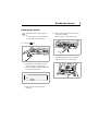
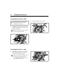
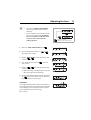
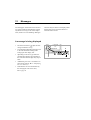
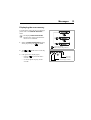
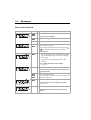
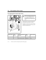
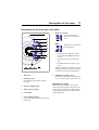
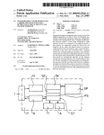
Operating Instructions
Tachograph 1324
Contents
System overview ..................................................................................................................... 1
General information .............................................................................................................. 2
Operating controls ................................................................................................................. 3
Enable the device ................................................................................................................... 5
Opening the drawer .............................................................................................................. 5
Inserting the driver 2 chart ................................................................................................... 6
Inserting the driver 1 chart ................................................................................................... 6
Setting the time groups ........................................................................................................ 8
Removing the charts .............................................................................................................. 9
Driver change ....................................................................................................................... 10
Adjusting the time ................................................................................................................ 11
Messages ............................................................................................................................... 12
A message is being displayed ............................................................................................ 12
Displaying the error memory ............................................................................................. 13
Error code Overview .......................................................................................................... 14
Troubleshooting ................................................................................................................. 15
Updating the chart carrier .................................................................................................. 15
Description of the chart ....................................................................................................... 16
The appropriate chart for the device .................................................................................. 16
Recordings on the front part of the chart ........................................................................... 17
Entries in the centre field ................................................................................................... 18
The rear side of the chart .................................................................................................... 19
Recording of failures ........................................................................................................... 20
Appendix ............................................................................................................................... 21
Compulsory inspection of tachographs .............................................................................. 21
Maintenance and cleaning .................................................................................................. 21
Definitions contained in these operating instructions
Driver 1
=
The person who is driving the vehicle at the moment or who will be
driving the vehicle.
Driver 2
=
The person who is not driving the vehicle.
System overview
1
Tachograph 1324
Indicating instrument
Charts
Sensor 2170
The new tachograph 1324 sets new standards in performance, technology, and design
due to its modular design with separate display and recording. The tachograph 1324,
which is in DIN radio compartment format, is
an innovative system component.
Within the immediate field of view of the
driver, there is an approved indicating
instrument with analogous vehicle speed
pointer, digital distance counter, time and
trip odometer. The function monitor
refers to messages of the tachograph 1324.
Driver 1 and driver 2 conveniently select the
respective working time groups via the control keys.
Together with the intelligent sensor 2170,
the system forms a reliable unit. The sensor
provides real-time pulses and encoded data
for recording the distance travelled and the
vehicle speed.
Besides the date, time and distance travelled,
the selected working time groups and the
symbols of the inserted charts are clearly
shown in the display. Failures at the device or
of a system component will be signalled
automatically.
Like before, the vehicle speed and the distance travelled as well as the driver specific
driving, working and break times are recorded on the tachograph chart.
May all your journeys be pleasant!
2
General information
The symbols in these operating instructions
have the following meanings:
ATTENTION!
The text next to this symbol contains
important information, which has to
be observed to prevent the device
from being damaged.
NOTES
or additional information, which, if
not observed, may lead to failures,
are marked by this symbol.
•
❒ Notes for the handling of the charts
•
The chart is driver-specific and may
thus not be transferred to other
persons!
•
Use charts provided by the manufacturer.
Make sure that the full-scale value and
the approval mark correspond to those
on the tachograph 1324, ➥ see page 16.
•
Only insert perfect charts, they may
neither be folded, nor be torn at the
perimeter and / or at the opening, nor be
wavy or damaged in any other way!
•
The recorded charts must be safely
stored and protected against damage, see
also Section 15 of the CR (EEC) No.
3821/85.
Please observe the notes listed
below!
❒ Notes for the operation of the
tachograph 1324
•
Only open the drawer for inserting or
removing the charts. Otherwise, keep it
shut at all times to avoid damages and to
prevent it from being contaminated.
•
Do not use the drawer as a kind of support, like for example, for writing on the
charts.
•
Do not use any abrasive detergents for
cleaning the device, nor any solvents like
diluent or naphtha.
The tachograph 1324 will be installed
and sealed by authorised persons.
Please do not intervene at the device
or at the supply lines.
❒ Reference to legal provisions
•
Those who modify the settings of the
controlling device or at the signal feed
line, which influence the record issued
by the controlling device, especially
when intending to deceive, may violate
official penal provisions or administrative regulations!
Operating controls
3
3
1
2
4
5
6
8
Tachograph 1324
7
4
Operating controls (see figure page 3)
1 Left-hand keypad
Key for unlocking the drawer.
Key for adjusting the time group
for driver 1.
2 Right-hand keypad
Key for adjusting the time group
for driver 2.
Key for selecting the following
functions:
• "Time Adjustment",
➥ see page 11.
•
Display "Error Memory",
➥ see page 13.
Keys for adjusting the time and for
displaying the current error messages.
3 Display
(lit up if the ignition is switched on)
• The basic display is shown permanently.
• Messages / notes are displayed
automatically, ➥ see page 12.
Date + time
Chart + time group
symbol, driver 2
Error symbol
Total kilometre reading
Chart + time group
symbol, driver 1
4 Checkpoint marking
for checking the temporally correct position of the chart carrier.
5 "Pear-shaped" chart carrier
6 Separating plate
between driver 1 and driver 2 chart.
7 Nameplate
The manufacturer, device type, inspection mark and serial number are indicated
here.
8 Hinged drawer
Enable the device
Opening the drawer
The drawer may only be opened,
if ...
• the vehicle is at a standstill and
•
2. Pull out the hinged drawer to the limit
stop and tip it down.
Remove driver 1 chart if necessary.
the ignition is switched on.
1. Press the
key.
3. Tilt separating plate entirely upwards.
Remove driver 2 chart if necessary.
½ In the display, the "Ejection active"
symbol is shown. Additionally, a
process indicator shows that this process may take some time.
½ Wait until the drawer has been
unlocked.
5
6
Enable the device
Inserting the driver 2 chart
Before starting to drive, the centre
field of the chart has to be duly
recorded, ➥ see page 18.
5. Tilt separating plate downwards.
4. The driver 2 inserts the recorded chart
with the front side facing up in the "pearshaped" chart carrier.
Make sure that the chart is located below the spring element (a).
a
Inserting the driver 1 chart
6. The driver 1 inserts the recorded chart
on the separating plate in the chart carrier with the front side facing up.
Make sure that the tachograph chart is
located under the holding-down
device (b) and the latches (c) of the
pear-shaped chart carrier.
b
c
Enable the device
Comment on 1 driver operation
In the 1 driver operation, only the chart for
driver 1 is to be inserted on the separating
plate.
7. Make sure that the position of the chart
carrier is temporally correct. The time
scale of the chart has to be adjusted to
the current time of the display at the
respective marker (d).
7
9. The basic display is shown:
½ including date, time, and the total
number of kilometres,
½ additionally, the symbols for the inserted charts, and current position of
the time groups, on the left for driver 1
and on the right for driver 2, are displayed.
d
½ If this is not the case, please start the
chart carrier settings update,
➥ see page 15.
8. Bring the hinged drawer into a horizontal
position and push it in until it latches.
Notes on the basic display
• The time of the tachograph 1324 is adjusted to the legal time of the country
where the vehicle has been registered.
The start and the end of the daylight
saving time are deposited within the
device and will be updated automatically.
➥ See also page 14 "Error code
overview".
• In case an exclamation mark appears
next to the total kilometre reading, there
has been a failure. ➥ See also page 14
"Error code overview".
8
Enable the device
Setting the time groups
2 driver operation
10. Driver 1 presses the
key.
½ Press the key several times, until the
desired time group is shown in the display.
11. Driver 2 presses the
key.
½ Press the key several times, until the
desired time group is shown in the display.
1 driver operation
• Only insert the chart for driver 1 on the
separating plate during 1 driver operation.
• Set the time group for driver 2 to break
time " ", otherwise there will be an error message.
Time group distribution
= driving times
= other working times
= availability
(waiting times, co-driver times,
times in sleeping cabin during ride)
= break times and resting periods
Driver 1
Driver 2
As soon as the vehicle starts to drive, the
tachograph 1324 will automatically record
• " " for driver 1
•
"
" for driver 2
and the corresponding symbols will appear in
the display.
Removing the charts
Remove your chart from the tachograph 1324
• in case of a change of driver or vehicle,
•
at the end of the working time
•
or after 24 hours at the latest.
The drawer may only be opened,
if ...
• the vehicle is at a standstill and
•
1. Press
the ignition is switched on.
key.
9
Comment
In case you have, however, switched off the
ignition, it is possible that the drawer does
not properly lock after closing. In this case,
please proceed as follows:
1. Switch on the ignition.
½ Wait until the ejection procedure has
been finished.
2. Then push in the drawer until it locks
into place.
3. Switch off the ignition again.
½ The "Ejection active"symbol is shown
in the display. A process indicator signals that the records on the charts are
being completed by the Tachograph 1324.
½ Wait until the drawer has been
unlocked.
Please do not switch off the ignition
while the "Ejection active" symbol is
shown on the display!
2. Pull out the hinged drawer to the limit
stop and tip it down.
3. Remove the charts and complete the
inscription in the centre field,
➥ see page 18.
4. Bring the hinged drawer into a horizontal
position and push it in until it latches.
Automatic switching off of the time
group and the distance recording
In case the drawer remains closed with the
charts inserted for more than 25 hours, the
tachograph 1324 automatically records the
time group " " for driver 1 and 2. The
tachograph 1324 thus goes easy on the vehicle batteries.
Notes on a standstill of the vehicle
If the vehicle will not be used for a
long time, please make sure that
there is no chart in the tachograph 1324; e.g. in case of maintenance or repair work or immobilisation of the vehicle.
10
Driver change
Chart
driver 2
Chart
driver 1
Case 1:
The crew changes among themselves, driver 2 becomes driver 1:
1. Exchange the charts.
½ Driver 1 (now driver 2) places his
chart below the separating plate and
driver 2 (now driver 1) on the separating plate.
2. Select the desired time groups.
½ The new driver 1 presses the key
,
the driver 2 the key
.
Case 2:
Driver 1 or driver 2 leaves the vehicle:
1. The respective driver takes his chart with
him.
Record as
driver 2
Driver change
Record as
driver 1
In case the driver changes the vehicle during
his daily working time, he has to take the
chart with him and note the vehicle change
on the rear of the chart.
2. The new driver 2 places his chart below
the separating plate.
or:
The new driver 1 places his chart on the
separating plate.
Comment
In case there is no new driver 2, the time
group has to be switched to break time " ",
otherwise an error message will be displayed.
Case 3:
Driver 1 and driver 2 both leave the
vehicle:
1. Both drivers remove their charts from
the device.
2. The new crew inserts the chart according
to their respective functions
(driver 1 or driver 2) in the device.
Adjusting the time
•
The function TIME ADJUSTMENT
may only be selected if the vehicle is
stationary.
•
For an automatic synchronisation of the
chart carrier and the time, the ignition
has to be switched on and there must
not be any chart inserted in the
tachograph 1324.
1. Select the TIME ADJUSTMENT via
2. Activate the minutes counter via
the minutes start to flash.
3. Depress
or
is being displayed.
or
.
,
key until the desired value
4. Activate the hours counter via
start to flash.
, the hours
5. Depress
or
key until the desired value
is being displayed.
½ When exceeding or undershooting 00:00, the
date will be adjusted automatically.
6. Acknowledge the time adjustment by depressing
the
key for more than 2 seconds. The basic
display will then be shown again.
Comment
If you adjust the time while a chart is inserted, the error symbol will be shown in the display and the time
will be flashing. The tachograph 1324 will remind
you to update the chart carrier settings;
➥ see page 15.
= Depress key shortly
= Depress key for a longer interval
11
12
Messages
The tachograph 1324 monitors the functioning of the system and automatically signals
any failure occurring in one of the components, the device or the handling. Messages
and notes may be shown in the display immediately after having closed the drawer or
when the failure occurs.
A message is being displayed
•
The function monitor
(1) at the indicating instrument is lit up,
•
an exclamation mark (2) will appear next
to the total kilometre reading in the
tachograph 1324 display and ...
•
depending on the error type either the
complete time display (3) is flashing or
the colon between the digits may stop to
flash.
•
Additionally, the error is recorded in an
electronical memory, ➥ see "Displaying
the error memory".
•
Some failures are also documented by
the tachograph 1324 on the chart,
➥ see page 20.
3
1
2
Messages
Displaying the error memory
To find out the reason for the error message
please refer to the ERROR MEMORY
menu.
The display ERROR MEMORY
function may only be selected if the
vehicle is at a standstill!
1. Select the ERROR MEMORY menu by
shortly depressing the
key twice.
= Depress key shortly
= Depress key for a longer interval
2. Via
or
be displayed.
, other active errors may
3. Call up the basic display again,
– Depress
key for more than 2
seconds
– or do not depress any key for 20
seconds.
Error start
Symbol with error code
Other error messages available
13
14
Messages
Error code Overview
Displayed message
Code
Meaning / measure
9 0 0 A = Error during CAN transmission
900B
Contact Volvo workshop.
9 0 0 F = Keypad error, key pressed too long or blocked
9 0 1 0 = LCD error (display)
9 0 5 1 = Driver 1 chart is missing
9 0 5 2 = Driver 2 chart is missing
(This message will appear when switching from
to , for example, while the chart is missing.)
Insert chart(s).
9053 =
(Time is flashing)
•
The tachograph 1324 has automatically changed
over to the beginning or the end of the daylight
saving time,
•
or the time has been adjusted with the chart
inserted.
Note: update the chart carrier settings,
➥ see page 15.
9 0 6 0 = Error at the drawer
Start the ejection procedure and close the drawer
again afterwards.
9 0 6 1 = Error in recording system
9062
(The tachograph 1324 will record these errors on the
9063
chart, ➥ see page 20.)
9 0 6 4 = Error during chart carrier settings update
(Time is flashing)
Update the chart carrier settings once again,
➥ see page 15.
9 0 6 4 = Error in the driving mechanism of the chart carrier
(Colon is not flashing)
Check whether the charts have been correctly
inserted.
Messages
Displayed messages
Code
15
Meaning / measure
9 4 30 = Error at "B7" v-pulse output
A 0 0C = Internal error
A 0 50 = Trip without driver 1 chart
(Error code cannot be found in the error memory.)
Insert driver 1 chart.
A 4 00 = Power loss
(Error code cannot be found in the error memory.
The tachograph 1324 will record a power loss on the
chart, ➥ see page 20.)
A423 = Error during sensor 2170 communication
A 8 22 = Error in sensor 2170 key / serial number / signal
(The tachograph 1324 will record these errors on the
chart, ➥ see page 20.)
Troubleshooting
After having remedied the error cause, e.g. in
case of an operating error, the message will
automatically be deleted.
In case one of the messages is shown
repeatedly, consult a authorized service workshop!
Updating the chart carrier
1. Open the drawer and remove both charts.
2. Close the drawer again.
½ The tachograph 1324 will automatically update the time of the chart carrier, and the error symbol and the time
will then stop to flash.
3. Open the drawer and insert new charts if
necessary. The tachograph 1324 will be
ready for use again.
16
Description of the chart
The appropriate chart for the device
When using (ordering) charts, always
ensure that the full-scale value (1)
and the approval mark (2) of the
tachograph 1324 correspond to the
details (3) or (4) on the chart respectively.
1
2
Outside the EU, the respective national approval marks and provisions are valid.
Depending on the full-scale value and the device design, you may use the following charts
within the tachograph 1324:
3
4
Standard chart
Volvo
part no.
Chart for electronical
evaluation
Volvo
part no.
Approval mark
125-24 EC 4K
3985719
125-24/2 EC 4B
20400028
e1-83
125-3300-24/2 EC 4B
20400029
e1-85
=
Chart for versions with engine speed recording (rpm).
Description of the chart
17
Recordings on the front part of the chart
1
2
7 Distance travelled
An up- or downward
movement corresponds to
5 km.
= 5km
3
Note
4
The distance recording will
be interrupted if ...
5
6
•
the time group switches have been
set to break time " " for both drivers and
•
the ignition has been switched off
and
•
the additional record (option) is not
active.
7
8
When the ignition is switched on, the recording of the distance will be continued
correctly in terms of time and position.
1 Time scale
2 Opening marker
Each opening of the drawer is being
recorded.
3 Speed recording in kph
4 Time group recording
5 Centre field
6 "Pear-shaped opening"
Ensures the temporally exact positioning
of the chart.
8 Additional recording (option)
Recording of additional working groups,
e.g.: use of blue light, a police siren, etc.
Evaluation of charts
Besides the direct reading of the records,
there is also the possibility of a precise evaluation of the recorded data. Further details
will be readily provided by a Siemens VDO
distributing centre.
18
Description of the chart
Entries in the centre field
a) ... before trip
name and first name of the driver
place of departure
date of insertion (upper line)
a)
vehicle registration number
beginning odometer reading
b) ... after trip
place of arrival
date of chart retrieval (bottom line)
ending odometer reading
distance travelled (may be entered)
b)
Comment
The entering of the name and first name as
well as statements on the beginning and the
end of the use is required by law and forms
the basis of a later evaluation of the chart.
Description of the chart
19
The rear side of the chart
c)
3
1
2
d)
2
3
1 Entry field for the time groups
This entry field is used for manual entries
of the time groups. Manual entries are
required if, for example, the crew
members work away from the vehicle
and therefore are not able to operate the
tachograph 1324 or else in case of a failure of the time group recording mechanism.
2 Centre field
In the centre field, up to three vehicle
changes may be entered manually.
The following data is required:
time of vehicle change
4
the registration number of the new
vehicle
4a
odometer reading at start of
journey
odometer reading at end of journey
distance travelled (may be entered)
The tachograph 1324 has two basic chart
types:
c) without rpm recording
d) with rpm recording
3 Approval mark field
This part of the rear side contains
information on the approval numbers of
the chart and the devices for which the
chart is approved.
4 RPM recording
The temporally exact recording (in rpm)
is carried out on the rear side of the chart
for driver 1.
Note
The markers (4a) will be displayed for
ignition on / off.
20
Recording of failures
1
2
Power loss
In case there is power available again, the tachograph 1324
will draw a line (1) on the chart shortly after the vehicle has
started to move.
Sensor 2170 disconnection
Failure of the transmission link between sensor 2170 Ø
tachograph 1324:
• As soon as the vehicle stands still, the marker (2) is
shown.
or
•
The marker (3) is displayed immediately after the failure and remains there,
until the cause of the failure has been remedied.
3
4
Device failures
Failures in the recording mechanism may
cause the following recording errors:
• Marker (4), defect within the v-recording mechanism.
•
5
6
Marker (5) and (6), defect within the recording mechanism for the time group and distance record.
Appendix
21
Compulsory inspection of tachographs
The vehicle owner is obliged to have the
installed tachograph 1324 inspected at
regular intervals.
At least once every two years, the proper operation of the tachograph 1324 has to be test-
ed, e.g. in conjunction with the technical
inspection of your vehicle.
Please ensure that the installation plate is
replaced at each inspection and contains the
information required.
Maintenance and cleaning
The tachograph 1324 is equipped with
modern, maintenance-free technology. For
this reason, preventive maintenance work is
not required.
In case they are dirty, you may clean the
housing, the display and the function keys by
means of a slightly moistened cloth. In case
this proves insufficient, special cleaning or
preservative agents for plastics may also be
used.
© 10.01 by Siemens VDO Automotive AG
Responsible for the contents:
Siemens VDO Automotive AG
Information Systems Commercial Vehicles
P.O. Box 1640
D-78006 Villingen-Schwenningen
All modifications of technical details compared to the
description, data and figures of these operating
instructions are reserved.
Volvo Truck Corporation
Göteborg, Sweden
20 151946
Printed in Sweden