1
Section 3 • Scheduled Maintenance Procedures
CHECKLIST B
PROCEDURES
REV K
3 Connect an appropriate power tool to the
inverter. Activate the tool.
B-15
Inspect the Voltage Inverter
(if equipped)
Result: The power tool should operate. There
may be a brief (0.5 second) delay if the power
tool has not been used in the previous 10
minutes.
Genie requires that this procedure be performed
every 250 hours or quarterly, whichever comes
first.
1 Inspect the inverter plug and pigtail for damage
or excessive insulation wear. Replace as
required.
2 Turn the key switch to the on position and pull
out the red Emergency Stop button to the on
position at both the ground and platform
controls.
b
a
FAUL
T
OUT
PUT
c
25V
POW
ER IN
VERT
ER
24V-2
2V
21V
d
PART
NUM
BER
XXX
a
b
c
d
February 2012
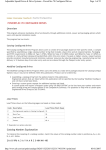
right fault LED
left fault LED
25V LED
21V LED
If the left fault LED (REV_POL) is illuminated,
the inverter is connected to batteries with the
incorrect polarity. Correct the polarity issue with
the red wire to battery positive and the black
wire to battery negative. The inverter will then
operate correctly and begin supplying AC
power.
If the right fault LED (123) blinks one time, the
power draw is too high. The tool being used
requires too much power to operate or is being
used at or near the limit of the inverter for an
extended period of time. Reduce the power
draw. The inverter will then operate correctly
and begin supplying AC power.
If the right fault LED (123) blinks two times, the
Ground Fault Interrupt (GFI) has been
activated. A short circuit or partial short exists
between the AC hot and ground in the tool or
outlet. Check the tool for burnt, chafed,
corroded and loose wires, and inspect the tool
for internal moisture. Correct the short circuit or
moisture issue OR inspect the wiring in the
power-to-platform box. The inverter will then
operate correctly and begin supplying AC
power.
If right fault LED (123) blinks three times, the
inverter is overheated. Allow the inverter to
cool. The inverter will then operate correctly
and begin supplying AC power.
If the battery 25 volt fault LED (25V) blinks one
time, the battery voltage is over 30V. Operate
the machine to lower the voltage level. The
inverter will then operate correctly and begin
supplying AC power.
If the battery 21 volt fault LED (21V) blinks one
time, the battery voltage is less than 20V DC.
The inverter will continue to operate until the
battery voltage falls to 17.8V DC.
3 - 24
GS-30 • GS-32 • GS-46
Part No. 97385