1
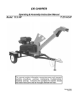
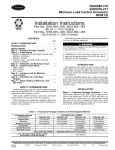
CHAPTER 7 FINAL DRIVE Final Drive Torque Specifications . . . . . . . . . . . . . . . AWD Operation Overview . . . . . . . . . . . . . . . . . . . . . . AWD Front Hub Disassembly . . . . . . . . . . . . . . . . . . AWD Hub/Bearing Installation . . . . . . . . . . . . . . . . . . AWD Front Hub Bearing Adjustment . . . . . . . . . . . . AWD Front Hub Exploded View . . . . . . . . . . . . . . . . AWD Hub Seal Replacement . . . . . . . . . . . . . . . . . . . AWD Magnetic Coil Service . . . . . . . . . . . . . . . . . . . . AWD Hilliard Clutch Disassembly/Inspection . . . . . AWD Armature Plate Inspection . . . . . . . . . . . . . . . . AWD Front Drive Axle Removal . . . . . . . . . . . . . . . . AWD Front Drive Axle Installation . . . . . . . . . . . . . . . AWD Front CV Joint Boot Replacement . . . . . . . . . AWD Front Drive Axle Exploded View . . . . . . . . . . . AWD Strut Casting Seal Replacement . . . . . . . . . . . AWD Strut Seal Sleeve Replacement . . . . . . . . . . . U-Joint Disassembly . . . . . . . . . . . . . . . . . . . . . . . . . . U-Joint Assembly . . . . . . . . . . . . . . . . . . . . . . . . . . . . . Front Eccentric Housing Service . . . . . . . . . . . . . . . . Center Eccentric Housing Service . . . . . . . . . . . . . . Center/Front Chain Tightner Exploded View . . . . . . Rear Drive Axle Service . . . . . . . . . . . . . . . . . . . . . . . Rear Axle Removal . . . . . . . . . . . . . . . . . . . . . . . . . . . Rear Axle Installation . . . . . . . . . . . . . . . . . . . . . . . . . 7.1 7.2 7.3 7.4 7.5 7.6 7.7 7.8 7.9 7.10 7.11-7.12 7.12 7.13-7.14 7.15 7.16 7.17 7.18-7.19 7.19-7.20 7.21 7.22 7.23 7.24 7.25 7.25 7 FINAL DRIVE WHEEL AND HUB TORQUE TABLE¡ ¡ Item Specification Front Wheel Nuts 20 Ft. Lbs. Rear Wheel Nuts 50 Ft. Lbs. Front Hub Nut Refer to text for procedure (Pg 7.5) Rear Hub Retaining Nut 80 Ft. Lbs. Refer to exploded views and text for torque values of other fasteners CAUTION: Locking nuts, and bolts with preapplied locking agent should be replaced if removed. The self-locking properties of the nut or bolt are reduced or destroyed during removal. 7.1 FINAL DRIVE AWD OPERATION OVERVIEW With the Polaris All Wheel Drive System activated (AWD selected), the machine operates as a 2 wheel drive vehicle until the rear wheels lose traction. If the rear wheels lose traction the front wheel rotational speed will decrease, causing the front drive axle speed to exceed front wheel speed. Restricting the rotation of the drive clutch roller cage (2) (see Electric Hub Operation) will cause the rollers (3) to climb the ramps of the cam (5), and become squeezed between the ramps and the ring in the hub. See Ill. 1. When the hub clutch assembly, wheel hub, and drive axle are engaged, the front wheels will drive and stay engaged until rear wheel traction is regained. When traction is regained, the front wheels will overdrive the hub clutch, pushing the clutch rollers (3) toward the lower part of the cam (5), disengaging the clutch. The rollers are held in place by the spring (4). See Ill. 2. The tension of this spring is critical to AWD hub operation. Always use the correct spring (refer to appropriate parts manual) and use installation tool PN 2870888. Ramps Hub Cage (2) Axle Roller (3) Cam (5) WARNING It is important that the front and rear axle drive ratio and tire size are not changed. Changing this ratio will cause erratic engagement, which could result in a loss of vehicle control and serious injury or death. Ill. 1 ELECTRIC HUB ENGAGEMENT (AWD) When AWD is selected in a forward gear, current flows through a coil of wire located in the strut housing, creating a magnetic field. An armature plate (1) coupled to the roller cage (2) is attracted to the magnetic field, and resists rotation, creating drag on the drive roller cage assembly. This causes the roller to climb the ramps of the cam, engaging the hub. NOTE: In reverse gear the override button must be pushed to deliver power to the wheel coil. Electric hub engagement offers an advantage over mechanical systems. When the AWD button is switched off, the machine will have the steering ease of a 2 wheel drive unit; and with the switch turned on, All wheel drive will be engaged whenever the rear wheels lose traction. 1. 2. 3. 4. 5. Spacer Tabs must engage the slots 3 A 1 Ill. 2 7.2 Armature Plate Roller Cage Roller Garter Spring Cam 2 4 5 FINAL DRIVE FRONT HUB REMOVAL (AWD) If an AWD problem is encountered, thoroughly inspect the electrical portion of the system as well as the front hub mechanism. Refer to the electrical chapter. 1. Carefully lift and support the front end of the machine as shown with the jack stands under the front end of the foot rests. CAUTION: Make sure the machine is solidly supported before proceeding. Serious injury could occur if the machine tips or falls. 2. Remove the front wheels and thoroughly clean the area around the hub, strut casting, brake caliper and brake disc. 3. Remove the two brake caliper attaching bolts. CAUTION: Do not hang the caliper by the brake hose. Use wire to hang the caliper to prevent possible damage to the brake line. 4. Place a catch pan beneath the front hub and remove the hub cap. 5. Remove cotter pin and nut. 6. Remove front hub and bearings. 7.3 FINAL DRIVE HUB/WHEEL BEARING INSTALLATION 1. Thoroughly inspect the hub internally. If the hub bearing sleeve is damaged or shows signs of movement, the hub assembly must be replaced. When the sleeve is pressed into the hub it should be flush with the outside surface of the hub. 2. Grease hub seal to allow it to slide over roller clutch components. 3. Install wheel hub inner bearing. NOTE: All bearings must slide freely onto the spindle. If bearings do not slide freely, wheel bearing torque will be affected. 4. Install wheel hub, outer bearing, washer, and attaching nut. NOTE: It is very important that the hub is not moved outward once installed, or the seal on the hub will disengage the armature plate. 7.4 FINAL DRIVE AWD FRONT HUB BEARING ADJUSTMENT WARNING The following bearing adjustments are very important. Incorrect adjustment will increase bearing wear, reduce braking action, and may affect front drive hub engagement, which could result in serious personal injury or death. 1. Torque spindle nut to 160-170 inch lbs. while rotating hub continuously. 2. Back off nut 1/2 turn. 3. Rotate axle several revolutions by raising rear of machine and rotating rear wheels with the machine in gear. 4. Re-torque hub nut to 108-144 inch lbs. Front Spindle Nut Torque: 108-144 in. lbs. Brake Caliper Retaining Bolt Torque: 18 ft. lbs. (25 Nm) 5. Install cotter pin. Bend each leg of cotter pin around castle nut in different directions. NOTE: If cotter pin hole does not align, tighten slightly to align and install pin. Do not exceed 144 in. lbs. 6. Reinstall hub cap. 7. Remove fill check plug and rotate hole to either 4:00 or 8:00 position. 8. Fill with Polaris Premium Demand Drive Hub Fluid or Type F Automatic Transmission Fluid until fluid trickles out. NOTE: Do not force the oil into the hub under pressure. This can cause seal damage and leaks. Premium Demand Drive Hub Fluid PN 2871654 (8 oz.) PN 2872277 (2.5 gal.) 9. Reinstall plug. 10. Reinstall brake caliper assembly. Torque retaining bolts to 18 ft. lbs. (25 Nm). 11. Reinstall front wheels. Torque retaining nuts to 15 ft. lbs. (21 Nm). 12. Carefully lower vehicle. 13. Field test vehicle for proper operation of brake system and AWD operation. 7.5 FINAL DRIVE AWD FRONT HUB EXPLODED VIEW Garter Spring Brake Disc Seal Armature Plate Detail Bearing (1.000 I.D.) A DETAIL A Front Hub Clutch Bearing Race Spacer Front Hub Clutch Bearing (1.000 I.D.) Castle Nut¡ Cotter Pin (Use new cotter pin) O-Ring Bearing Race Washer Wheel Nut ¡Refer to text on page 7.5 for more information. 7.6 FINAL DRIVE AWD HUB SEAL REPLACEMENT 1. Remove and disassemble front hub. Refer to page 7.3. 2. Remove brake disc attaching bolts and brake disc. NOTE: If the attaching bolts are difficult to remove, it may be helpful to heat the outer surfaces of the hub in the area of the disc mounting bolts, to soften the locking agent. 3. Apply heat to the hub seal area. When the hub becomes too hot to touch, pry out the old seal as shown. Do not damage the surface of the seal cavity. Clean the hub in the seal mating area. 4. With spring side of new seal facing toward hub casting, press it in until flush with brake disc mating surface. CAUTION: Do not use a hammer as damage to the seal will result. 5. Thoroughly clean the brake disc with brake cleaner. It is very important that the brake disc be free of any oil or solvents. 6. Reinstall the brake disc using genuine Polaris OEM bolts that have a pre-applied locking agent. Do not substitute bolts or use old ones. 7. Install attaching bolts and torque to 18 ft. lbs. (25 Nm). 7.7 FINAL DRIVE MAGNETIC COIL REMOVAL 1. Remove the front drive axle as described later in this chapter. 2. Remove the seal sleeve from the strut casting using a drift punch and hammer, tapping evenly on each side until the sleeve slides off. 3. Remove the existing coil and clean the coil wire channel, coil mount area, and the seal sleeve mounting area of all silicone and foreign matter. 4. Disconnect the coil wires at the connector or terminal board. Strut Ribs MAGNETIC COIL INSTALLATION Coil Wire Channel 1. Apply 1/4I (.6 cm) bead of silicone in the coil wire channel. 2. Install the coil to the coil mount surface and press the coil wires into the silicone in the coil wire channel. 3. Apply 1/4I (.6 cm) bead of Loctite Ultra Blue silicone around the seal sleeve mounting area. NOTE: This includes applying silicone over the coil lead wires again. Always allow 12 hours’ cure time for silicone. 4. Press on the seal sleeve until even with the inner pole. See page 7.17 for additional information. Once the seal sleeve is properly positioned, a 1/16I (.16 cm) bead of silicone should remain around the inner edge. Clean off all excess silicone. The seal sleeve area must be free of silicone or the hub seal may leak. NOTE: - Always install a new seal sleeve when replacing the coil. Use tool PN 2871199. - It may be necessary to apply more silicone (or an equivalent fast drying glue) to the wire channel area to properly secure and protect the coil wires. 5. Apply 401 Loctitet to the inside of the strut ribs and press the foam block to contain the coil wires. Make sure the foam block is bonded well to protect the coil wires. NOTE: Coil wires must be contained in the brake line clip on the back side of the upper strut casting and the wires must be snug against the casting. 6. Route the wires smoothly and away from any moving parts and secure in place with tie straps. 7. Assemble front axle and connect hub wires. 7.8 Brake Line Clip Location Seal Sleeve Mounting Area Coil Mounting Surface (Inner Magnet Pole) (Fixed) Electromagnet Coil Seal Sleeve (Outer Magnet Pole) (Adjustable) Must use tool PN 2871199 FINAL DRIVE HILLIARD CLUTCH DISASSEMBLY/INSPECTION 1. Remove front hub. See page 7.3. 2. Remove Hilliard clutch assembly. 3. Disassemble the roller clutch and thoroughly clean all parts. CAUTION: Do not remove the garter spring. If the spring is removed, it will become over stressed and will require replacement. 4. Inspect roll cage sliding surface (A). This surface must be clean and free of nicks, burrs or scratches. Inspect roller cage (2) carefully for cracks. 5. Inspect rollers (3). The rollers must slide up and down freely within the roller cage sliding surfaces A. 6. Without removing the garter spring, 1. Armature Plate NOTE: Armature plate is positioned with inspect the coils for consistency. If tabs in round holes of cage. coils are distorted or uneven, cut the 2. Roller Cage old spring with a side cutter to remove 3. Roller it, and replace it. 4. Garter Spring Inspect for cracks 5. Cam Spacer Engage tabs in the slots 3 5 A 1 7. If garter spring replacement is necessary, it is very important that the correct installation procedure and special tool be used. Hold rollers in place on roller cage with a light film of grease. Gently and evenly roll the spring down the tapered tool (PN 2870888) and into the groove of the rollers and cage. WARNING: If this procedure is not followed the spring will be over stressed and lose its tension. Springs with incorrect tension may allow rollers to move outward at high vehicle speeds. If the rollers move outward, the front hub(s) will engage and cause vehicle instability, which could result in serious injury or death. WARNING: Be sure to use correct garter spring. These springs are very similar in appearance to those used on earlier models. If the old, lighter springs were installed on a machine requiring the heavier spring, the front wheels may engage at high speed, possibly resulting in serious injury or death. Check springs before installation. Always verify the correct replacement spring part number by referring to the appropriate parts manual. Current electro-mechanical spring, PN 3250032; wire diameter .018 (.46 mm); spring free length end to end inside hooks 6.968 (177 mm). 2 4 Must use tool to install garter spring PN 2870888 Measure wire diameter Measure free length to inside of loops as shown 7.9 FINAL DRIVE AWD ARMATURE PLATE INSPECTION 1. As the armature plate is engaged, it should contact the outer magnet pole (seal sleeve) and the inner magnet pole. Also, the armature plate must be flat when placed on a flat surface. Bent armature plates should be replaced. NOTE: It is not unusual to see a double wear ring on the armature plate; however, the wear rings should be even. 2. Install the roller clutch (Hilliard Clutch) assembly and be sure the armature plate (A) is positioned properly. Also, when installing the hub assembly, be sure the armature plate tabs remain engaged with the roller clutch cage. Seal Sleeve CAUTION: After the hub is installed, the slightest movement outward with the hub may cause the armature plate tabs to disengage from the roller clutch cage. If the unit is driven with the armature plate out of position, it will cause roller clutch damage. Armature Plate Tabs 7.10 FINAL DRIVE AWD FRONT DRIVE AXLE REMOVAL 1. Loosen front wheel nuts slightly. 2. Elevate and support machine under footrest/frame area with front wheels elevated. CAUTION: Serious injury may result if machine tips or falls. Be sure machine is secure before beginning this service procedure. Wear eye protection when removing and installing drive axles or component parts. 3. Remove wheel nuts and wheels. 4. Remove hub cap. 5. Remove the two brake caliper attaching bolts. CAUTION: Do not hang the caliper by the brake hose. Use wire to hang the caliper to prevent possible damage to the brake line. 6. Place a catch pan beneath the front hub and remove the hub cap. 7. Remove cotter pin and nut. 8. Remove hub, bearings, hilliard assembly, and armature plate. 7.11 FINAL DRIVE AWD FRONT DRIVE AXLE REMOVAL, CONT. 9. Remove cotter pin and nut from lower A-arm ball joint. Remove lower A-arm from ball joint. 10. Using roll pin remover P/N 2872608, remove roll pin at front housing. Roll Pin Remover Tool P/N 2872608 11. Remove the spindle and axle assembly from the strut casting bearing by pulling the strut outward as shown. Drive out the old seal, taking care not to damage the tapered roller bearing. Install the new seal until it bottoms against the shoulder in the strut casting. AWD FRONT DRIVE AXLE INSTALLATION 1. Install spring washer and drive shaft. Align hole in U-joint yoke with hole in eccentric shaft, and install new roll pin. 2. Install new seal in strut casting. Refer to page 7.16. 3. Install drive shaft in strut. 4. Install lower ball joint, torque nut to 25 ft. lbs. (34.5 Nm) and install new cotter pin. 5. Follow procedure to install hilliard clutch components and hub as outlined on page 7.9. 6. Tighten hub nut following procedure on 7.5. 7.12 FINAL DRIVE DRIVESHAFT AND CV JOINT HANDLING TIPS Care should be exercised during driveshaft removal or when servicing CV joints. Driveshaft components are precision parts. Cleanliness and following these instructions is very important to ensure proper shaft function and a normal service life. S The complete driveshaft and joint should be handled by getting hold of the interconnecting shaft to avoid disassembly or potential damage to the driveshaft joints. S Over-angling of joints beyond their capacity could result in boot or joint damage. S Make sure surface-ground areas and splines of shaft are protected during handling to avoid damage. S Do not allow boots to come into contact with sharp edges or hot engine and exhaust components. S The driveshaft is not to be used as a lever arm to position other suspension components. S Never use a hammer or sharp tools to remove or to install boot clamps. S Be sure joints are thoroughly clean and that the proper amount and type of grease is used to refill when joint boots are replaced and when joints are cleaned. Refer to text for grease capacity of CV joints and CV joint boots. FRONT DRIVE SHAFT CV JOINT BOOT REPLACEMENT 1. Remove wheel, brake caliper and wheel hub. Refer to front hub disassembly page 7.3 for procedure. 2. Remove cotter pin and castle nut from A-arm ball joint. 3. Disconnect A-arm from ball joint using a tie rod fork. 4. Slide strut off end of drive shaft and tie it up out of the way of the shaft. NOTE: Be careful not to damage the wheel coil wires when positioning the strut. Front Drive Shaft CV Joint Boot Replacement Cont. 7.13 FINAL DRIVE FRONT DRIVE SHAFT CV JOINT BOOT REPLACEMENT, CONT. 5. Remove clamps from rubber boot using the proper boot clamp pliers. Retaining ring 6. Remove the large end of the boot from the CV joint, slide the boot back and separate the wheel spindle and CV joint assembly from the axle shaft by pulling the shaft sharply outward, away from the CV joint. It may be necessary to tap the CV joint assembly outward with a soft faced hammer. 7. Remove small clamp and boot from driveshaft. Pull shaft to remove from CV joint If the ATV has been operated with a damaged boot, the CV joint grease may be contaminated. Inspect the grease carefully for contamination, and clean the joint thoroughly if necessary. Front drive axle CV boot replacement requires 30g of grease. If CV joint is cleaned, an additional 30g of grease is required. Refer to information below. 8. Before installing the new boot, remove all grease from the boot area and shaft. NOTE: It is very important to use the correct type and quantity of grease by using the grease contained in the boot kit. DO NOT use a substitute grease and DO NOT overfill or underfill the CV joint. 9. Slide the new clamp and boot (small end first) over the splined shaft, then slide (tap) the CV joint into the splines of the axle. Install small boot clamp. 10. Add grease through large end of boot. 11. Position large end of boot on CV joint, purge excess air by partially compressing axle into CV bell, lift one edge of boot to let out excess air Secure with clamp. Joint Capacity 30 Grams CV Joint Grease - 30g PN 1350046 CV Boot Clamp Pliers: Earless Type 8700226 Boot Replacement requires 30g Boot replacement with complete CV joint cleaning requires an additional 30g. (Total 60g) FRONT SHAFT Boot Capacity 30 Grams Front outboard joint capacity: 30g if boot is replaced only. Another 30g (60g total) if joint is cleaned. 7.14 FINAL DRIVE AWD FRONT DRIVE AXLE EXPLODED VIEW Front Drive Axle Components Boot CV Joint Assy Clamps Drive Axle Circlip Yoke U--Joint Assy 7.15 FINAL DRIVE AWD STRUT CASTING FRONT DRIVE AXLE SEAL REPLACEMENT 1. Disassemble front hub. Refer to page 7.3. 2. Remove the cotter pin and castle nut from the Aarm ball joint. Separate A-arm from ball joint. 3. Remove the spindle and axle assembly from the strut casting bearing by pulling the strut outward as shown. Drive out the old seal, taking care not to damage the tapered roller bearing. Install the new seal until it bottoms against the shoulder in the strut casting. Pull strut off drive shaft 4. Apply grease to the seal inner lip, reinstall the spindle and axle assembly. 5. Reinstall the A-arm to the ball joint. Torque to 25 ft. lbs. (35 Nm). NOTE: If the cotter pin hole does not align at the above torque, tighten slightly until the cotter pin hole aligns and install the pin with open ends toward rear of machine. BEARING REPLACEMENT NOTE FOR FRONT DRIVE AXLE AND FRONT HUB NOTE: The front axle bearings have a larger I.D. (1.0625) than the hub bearings (1.000). Be sure to install the bearings with the larger I.D. in the strut housing, and the bearings with the smaller I.D. in the hub. 7.16 FINAL DRIVE SEAL SLEEVE REPLACEMENT Front Drive Axle Seal Sleeve 1. If front axle sleeves become damaged and leak fluid they are replaceable. Using a hammer and drift punch, remove the seal sleeve by driving it off evenly being careful not to nick or damage the sleeve mounting area (A). 2. Coat the sleeve mounting area (A) with silicone and using extreme care, press the new seal sleeve onto area (A) until it bottoms. Allow 12 hours for silicone to cure. NOTE: New front drive axle CV joint assemblies and drive axle assemblies have the seal sleeve installed from the factory. Seal Sleeve A Hub Seal Sleeve Replacement 3. The hub seal sleeve must be driven onto the strut casting until flush with the inner magnet pole. Use the flat side (no step) of tool PN 2871199. 4. To check the gap between the inner and outer poles place a straight edge on the outer pole so that it just intersects with the inner pole. The gap between the straight edge and inner pole should be 0 to .001I (0-.025mm). This measurement should be checked in three different positions around the pole assemblies. The three measurements must be within .0005I (.013 mm) of each other. If the gap is excessive, the hub may not engage. Pole Gap: .000-.001 (.00-.025mm) Not Unusual To See Two Wear Rings Inner Magnet Pole (Fixed) Coil Max. .001 (.025mm) Measure at 3 places 120_ apart Seal Sleeve (Outer Magnet Pole) (Adjustable) Seal Sleeve Installation Tool Set PN 2871199 Seal Sleeve Tool Use flat side to install seal sleeve Step Seal Sleeve (Outer Magnet Pole) Inner Pole Shoe 7.17 FINAL DRIVE U-JOINT DISASSEMBLY CAUTION: Always wear eye protection. 1. Remove internal or external snap ring from all bearing caps. NOTE:If yoke or bearing is removed, cross bearing must be replaced. Note orientation of grease fitting and mark inner and outer yoke for correct re-positioning during installation. 2. Support inner yoke as shown and drive outer yoke down (bearing cap out) with a soft face hammer. 3. Support U-joint in vise as shown and drive inner yoke down to remove remaining bearing caps. 7.18 FINAL DRIVE U-JOINT DISASSEMBLY CONT. 4. Force U-joint cross to one side and lift out of inner yoke. U-JOINT ASSEMBLY 1. Install new bearing caps in yoke by hand. Carefully install U-joint cross with grease fitting properly positioned inward toward center of shaft. Take care not to dislodge needle bearings upon installation of cross joint. Tighten vise to force bearing caps in. 2. Using a suitable arbor, fully seat bearing cap in one side. Continually check for free movement of bearing cross as bearing caps are assembled. 3. Install snap ring to contain bearing cap just installed. Repeat procedure for other side. 7.19 FINAL DRIVE U-JOINT ASSEMBLY, CONT. 4. Install outer yoke, aligning marks made before disassembly. 5. Repeat steps 1-3 to install bearing caps on outer yoke. 6. Seat all bearing caps against snap rings by supporting cross shaft and tapping on each corner as shown. 7. When installation is complete, Yokes must pivot freely in all directions without binding. If the joint is stiff or binding, tap the yoke lightly to center the joint until it pivots freely in all directions. 7.20 FINAL DRIVE FRONT ECCENTRIC HOUSING SERVICE Grease Fitting Spacer Eccentric Housing Shaft Bearing Seal O-Ring Front Eccentric Removal / Installation Procedure S Remove front drive axles from eccentric as outlined on page 7.11. NOTE: It is not necessary to disassemble the front wheel hub. S Pull strut and axle off eccentric shaft. S REMOVE front eccentric housing pinch bolt. S Rotate eccentric housing until opening in eccentric casting aligns with stop bracket. S Remove housing out left side of vehicle. Note location of foam spacer. S Reverse removal procedure to install. S Refer to Maintenance Chapter 2 to adjust chain. Front Eccentric Disassembly / Assembly Procedure Remove spacers and O-rings from both ends of shaft. Tap on end of shaft with a soft faced hammer to drive seal and bearing out opposite end of housing. Remove bearing from shaft and re-install shaft to drive other bearing and seal from housing. Inspect shaft for wear in the bearing area. Inspect housing for wear, cracks, or damage. Warm the housing and place bearings in freezer to ease assembly. Install a new bearing, pressing on the outer race only, until bearing is fully seated in left end of housing (left side has grease fitting). Outer race of bearings must fit tightly in housing. S Turn housing over and support inner race of bearing installed in previous step. S Install shaft. S S S S S S S 7.21 FINAL DRIVE CENTER ECCENTRIC HOUSING SERVICE Tapered Bearing Center Eccentric Assembly Procedure S S S S S S S S S S S S S S Press bearing races into housing. Lubricate and install bearings and seals. Install shaft. Install O-ring, spacer, sprocket, and washer on outer end of shaft. Loosely install nut on outer end of shaft. Loosen front eccentric pich bolt and rotate eccentric to provide maximum chain slack. Install front drive sprocket (inner), washer, and lock washer on inner end of shaft. Install eccentric assembly in frame. Tighten outer sprocket nut to 10 inch pounds. Loosen nut one full turn. Tighten nut to final torque of 15-20 inch pounds. Install cotter pin. Lubricate housing. Install and adjust chains (refer to maintenance section for adjustment procedure. NOTE: The outer sprocket castle nut sets bearing preload and is tightened to a very low torque - 5-10 inch pounds initially, and then finally 15-20 inch pounds. Be sure to tighten properly following procedure above. Inner Sprocket Bolt Torque: 30 ft. lbs. (41 Nm) Sprocket Lock Washer Washer Seal Front of vehicle Shaft Bearing Bearing Race Housing Bearing Race Cotter Pin O-Ring Spacer Nut 7.22 Washer Sprocket Seal Bearing Grease Fitting FINAL DRIVE CENTER / FRONT CHAIN TIGHTENER EXPLODED VIEW 7.23 FINAL DRIVE REAR DRIVE AXLE SERVICE 150 ft. lbs. (207 Nm) Apply Loctitet 242 Hub 50 ft. lbs. (69 Nm) Retainer Spacer O-ring Seal Grease 80 ft. lbs. (110 Nm) Bearing Spacer Bearing O-ring Bearing Seal 80 ft. lbs. (110 Nm) Flat Washer Cone washer tapered to outside Out Cone Washer 35 ft. lbs. (48 Nm) Lubricate hub splines with light film of grease. Replace all cotter pins if removed. Rear Axle Bend The rear axle shaft is hardened to approximately 3 to 4 (7.6 to 10 cm) from the outer ends. This allows the shaft to bend in case of impact or accident. Small amounts of axle runout can be straightened using V blocks, a hydraulic press, and a dial indicator. CAUTION: Do not use heat on any part of the axle. Heat will destroy the temper and cause the shaft to become brittle. 7.24 FINAL DRIVE REAR AXLE REMOVAL REFER TO EXPLODED VIEW ON PAGE 7.24 1. Elevate and safely support machine under footrest/frame area. CAUTION: Serious injury may result if machine tips or falls. Be sure machine is secure before beginning this service procedure. Wear eye protection when removing and installing bearings and seals. 2. Remove wheels and hubs. 3. Hold inner axle nut and remove outer axle nut. 4. Remove axle nut and washer. 5. Place a block of wood on end of axle or use a soft face hammer, and drive axle out from right to left. 1 3/4 Axle Nut Wrench PN 2870772 6. Tap locating collar on left side of axle toward the right enough to expose the circlip retainer. Remove retainer and locating collar. 7. Inspect locating collar on left side of axle and replace if worn or damaged. A worn collar will allow dirt to enter axle bearing area. REAR AXLE INSTALLATION 1. Slide locating collar on left end of axle with recess facing outward. 2. Install a new circlip. 3. Tap locating collar back towards left end of axle until it captivates circlip. 4. Apply a light coat of grease to axle and install a new O-Ring. 5. Insert axle from left to right. 6. Install O-Ring, sprocket hub, and washer. 7. Clean axle nut threads with a wire brush. Apply Loctite 242 to threads and install axle nut. Torque to 150 ft. lbs. (207 Nm). Rotate axle and check for smooth operation. 8. Install lock nut and torque to 150 ft. lbs. 9. Lightly grease splines of axle and install wheel hubs, flat washers, and cone washers with concave side facing flat washer. 10. Torque hub nuts to 80 ft. lbs. (110 Nm) and install new cotter pin, bending one leg of cotter pin inward and one outward against end of axle. 11. Install hub cap. Rear Axle Retaining Nut: 150 ft. lbs. (207 Nm) Rear Hub Retaining Nut: 80 ft. lbs. (110 Nm) Rear Wheel Nuts: 50 ft. lbs. (69 Nm) 12. Place wheels on hubs and install wheel nuts with tapered side facing in. Torque evenly to specifications. 7.25 NOTES