1
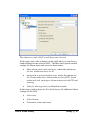
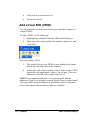
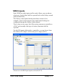
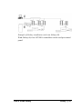
User’s Guide Galaxy
ASSA ABLOY
© Copyright 2003-2008, ASSA ABLOY
ASSA ABLOY
Förmansvägen 11
SE-117 43 Stockholm
Phone: +46 (0)8-775 16 00
Fax: +46 (0)8-775 16 20
UG 559 012 921F
Contents
Galaxy
3
About Galaxy alarm
Prerequisites
Hardware
License
Communication line 1
Installation
Galaxy in the installation tree
Add Galaxy control panel
Connect controller to Galaxy control panel
Galaxy in the alarm tree
Add Galaxy zone
Add DAC
Add virtual RIO (VRIO)
VRIO inputs
VRIO outputs
Galaxy Planning Guide (basics)
Alarm Operations
Activate Alarm (ON)
Activate alarm with forced start
Inactivate Alarm (OFF)
Disarm after Triggered Alarm
Summary Galaxy Alarm Operations
3
4
4
4
4
5
6
6
8
10
10
14
16
17
20
21
24
24
24
25
26
27
Glossary of Terms
29
Index
31
User's Guide Galaxy
Contents • iii
iv • Contents
User's Guide Galaxy
User's Guide Galaxy
Galaxy • 1
Galaxy
About Galaxy alarm
As an additional feature ARX ACCESS can be integrated with the
Galaxy intruder alarm system. If these two systems are integrated
you will get an overall solution which covers both access control
and intruder alarm monitoring.
A complete Galaxy system consists of a number of modules, which
controls the alarm systems different settings and functions. The
main modules are:
•
Control panel (central unit)
•
Key pad
•
RIO (Remote Input/Output) expansion module
(For more information about the Galaxy intruder alarm, please see
the Galaxy system manuals.)
User's Guide Galaxy
Galaxy • 3
Prerequisites
This section describes the prerequisites that must be met in order
for the Galaxy system to fully function together with ARX
ACCESS.
Hardware
The controllers must be equipped with communication cards of the
type “9014 II” or later. This in order to have access to the sixth
terminal block which enables connection to Galaxy.
License
To make the Galaxy functions accessible in the ARX ACCESS
client you are required to have a license that covers these Galaxy
features. Without such a license the Galaxy functions are not visible
to the user, but all the standard ARX ACCESS features will work.
Communication line 1
The controller that is assigned a serial interface (RS232, Tele
module, ISDN or TCP/IP) must be connected to the first
communication line of the Galaxy control panel, communication
line 1.
Units that not are assigned a serial interface can be connected to
any of the communication lines.
NOTE! Only one controller per installation can be assigned a serial
interface. Therefore for the other controllers the option Serial
interface must be set to “None” in ARX ACCESS.
4 • Galaxy
User's Guide Galaxy
Installation
To connect a LCU9016 controller to a Galaxy control panel (central
unit), follow these steps:
1.
Connect the outgoing lines A and B from the control panel
(Galaxy) to the connections marked “A” and “B” on the
terminal block in the lower right corner of the 9014 card in
the controller cabinet.
2
3
4
FREE A
1
B
0V
RS-485
Diagram of the terminal block in the lower right corner of the 9014
card
The first from the left on the terminal block is labelled FREE and
can be used to join any additional wires. The FREE connection is
not electrically connected to the 9014 card.
For additional information regarding the LCU9016 controller
please study the “ARX ACCESS Installation Manual”. For further
information about the Galaxy units, see the Galaxy system manual.
User's Guide Galaxy
Galaxy • 5
Galaxy in the installation tree
In the ARX ACCESS client the specific Galaxy functions are
managed through two windows: Installation tree and Alarm tree.
In the installation tree you add the Galaxy control panels (central
units) that are available, and specify which ARX controllers that
will be connected.
Add Galaxy control panel
To add a Galaxy control panel, do the following:
1.
Highlight the level in the installation tree where the control
panel shall be located under.
2.
Then select the option Add in the window menu bar, and
click Galaxy control panel.
Menu for adding Galaxy control panel
3.
The symbol for the new control panel is now added to the
installation tree on the left hand side of the window.
4.
In the right side of the window, enter a name for the new
control panel in the field Name, and add a brief description.
6 • Galaxy
User's Guide Galaxy
Installation tree window with a Galaxy control panel selected
5.
Click OK if you want to save the changes and close the
window. Click Cancel if you want to close the window and
not save the changes. Click Apply if you want to save the
changes and at the same time keep the window open.
User's Guide Galaxy
Galaxy • 7
Connect controller to Galaxy control
panel
To add a controller to a Galaxy control panel, do the following:
1.
Highlight the Galaxy control panel that the controller shall
be connected to.
2.
Then select the option Add in the windows menu bar, and
click Controller to serial line.
Menu for adding controller to serial line
3.
8 • Galaxy
The symbol for the controller is now added to the
installation tree on the left hand side of the window.
User's Guide Galaxy
The installation tree with a controller connected to Galaxy
4.
For each controller connected to a Galaxy control panel,
enter the correct Line number and choose type of Serial
interface for the connection.
NOTE! Only one controller per installation can be assigned a serial
interface. Therefore for the other controllers the option Serial
interface must be set to “None”.
NOTE! If there already is one unit in the Galaxy installation that is
communicating with the control panel through to a certain serial
interface, it is not possible to use the same interface for the
connected controller.
For example, you can not select the option “RS232” as serial
interface for the connected controller if there already is an external
PC communicating with the Galaxy control panel via the RS232
interface.
User's Guide Galaxy
Galaxy • 9
Additionally, it is possible to replace the serial interface RS232 by
tunnelling the traffic between a PC with the Galaxy Gold software
and the Galaxy control panel over a local area network (LAN) via
the connected controller. In such cases you should in Galaxy Gold
create a TCP/IP-connection with the controllers IP address and port
number 4900.
Galaxy in the alarm tree
If Galaxy control panels and connected controllers have been added
in the Installation tree window, these units will automatically
appear in the Alarm tree view. In the alarm tree it is then possible to
add Galaxy alarm zones and set alarm group settings for that zone.
In ARX ACCESS it is possible to choose if a controller shall act as
a virtual RIO, or VRIO. In such cases the controller communicates
with the Galaxy system in the same way as a traditional Galaxy
RIO.
Add Galaxy zone
To add a Galaxy zone, do the following:
1.
Highlight the Galaxy control panel that the zone shall
belong to.
2.
Then select the option Add in the windows menu bar, and
click Galaxy zone.
Menu for adding Galaxy zone
3.
The symbol for the zone is now added to the alarm tree on
the left hand side of the window.
10 • Galaxy
User's Guide Galaxy
Galaxy zone selected and the tab Settings active
4.
In the right side of the window under the Settings tab, enter
a Name for the new zone and add a brief Description. You
must also select a Group (Galaxy alarm group) for the zone
and choose settings for Alarm bypass by schedule and Time
limited disarming.
5.
In the same window, under the Access categories tab you
can enter the access categories that shall be valid for this
zone. Add categories by clicking the Add button, select a
category and then click OK
User's Guide Galaxy
Galaxy • 11
Galaxy zone selected and the tab Access categories active
6.
On the third tab, Pre alarm config, the operator can set the
Time in seconds before the alarm goes on and also connect
to a number of relay outputs to the zone.
NOTE! No pre alarm will sound if you turn on the alarm
via a Galaxy key pad (MAP).
12 • Galaxy
User's Guide Galaxy
Galaxy zone selected and the tab Pre alarm config active
7.
Select the Add button to choose which relay output and unit
(controller or DAC) that shall be added. Highlight a unit,
select relay output and click OK.
8.
In the Alarm tree window, click OK if you want to save the
changes and close the window. Click Cancel if you want to
close the window and not save the changes. Click Apply if
you want to save the changes and at the same time keep the
window open.
User's Guide Galaxy
Galaxy • 13
Add DAC
To add a DAC to a Galaxy zone, do the following:
1.
Highlight the Galaxy zone that the DAC shall belong to.
2.
Then select the option Add in the windows menu bar, and
click DAC.
Menu for adding DAC
3.
In the window that now opens, choose the DAC to add
from the list over Available DACs.
NOTE #1! A DAC can not belong to a Galaxy zone and a
standard alarm zone at the same time.
NOTE #2! If you have an elevator in your Galaxy
installation, each DAC can only belong to one Galaxy zone.
4.
The symbol for the DAC is now added to the alarm tree.
14 • Galaxy
User's Guide Galaxy
The alarm tree with a DAC in a Galaxy zone selected
In the upper part of the window (on the right side) you can choose
alarm settings for the selected DAC. The three first options control
settings for alarm status and access to alarm zones:
•
Show alarm status when alarm for, where the options are
No one, Authorized users or All.
•
Authorized to activated alarm zone, where the options are
No, Alarm authorized, Alarm authorized with PIN, Alarm
authorized with warning or Alarm authorized with PIN and
warning.
•
Time for showing status, is defined in seconds.
In the same window there are five check-boxes for additional alarm
settings for the DAC:
•
Allow arm
•
Allow disarm
•
Permanent alarm indication
User's Guide Galaxy
Galaxy • 15
•
Unlock door at disarmed area
•
Do not block door
Add virtual RIO (VRIO)
To each controller connected to Galaxy you can add a number of
virtual VRIO's.
To add a VRIO, do the following:
1.
Highlight the controller that the VRIO shall belong to.
2.
Then select the option Add in the windows menu bar, and
click VRio.
Menu for adding VRIO
3.
The symbol for the new VRIO is now added to the alarm
tree on the left hand side of the window.
4.
In the right side of the window, enter a Name for the VRIO,
and choose the appropriate Address for the unit. There are
addresses available in the range from 0 to 15.
NOTE! On communication line 1 it is quite normal that the
addresses 0 and 1 are already occupied by the Galaxy control panel.
This may differ from installation to installation and it is therefore
best to first check which addresses that are available.
16 • Galaxy
User's Guide Galaxy
VRIO inputs
Each VRIO has eight inputs and for each of these you can choose
what type of action that shall be reported back to the Galaxy control
panel (central unit).
The Galaxy control panel decides the alarm reaction if, for
example, a door is forced open. The control panel settings are
configured through the Galaxy Gold software.
This is done in two steps, first if the action concerns a controller or
a DAC and secondly what type of action (function) shall be
reported
For the RIO inputs dedicated to a controller, you can choose from
the actions LCU tamper or External power supply failure.
Alarm tree with RIO input option selected (LCU)
User's Guide Galaxy
Galaxy • 17
For the RIO inputs dedicated to a DAC, you can choose from the
actions:
•
Door forced open, initiates alarm if the door is forced open,
no information sent at valid passage.
•
Door open o long, initiates alarm if the door stays open to
long after a valid passage.
•
Door forced open or door open to long (same as the two
options above)
•
Assault alarm, sends alarm when the PIN code is raised by
1000 (Example: ordinary PIN “1234” – assault PIN
“2234”)
•
Invalid PIN, initiates alarm if an invalid PIN is entered
•
Free indication input (unbalanced input for logical
functions by the Galaxy control panel)
•
Day/Night input, same function as above but only acts if a
motorised lock is installed.
•
Door open/closed, sends status to the Galaxy control panel
regardless of if the passage is valid or not.
18 • Galaxy
User's Guide Galaxy
Alarm tree with RIO input option selected (DAC)
User's Guide Galaxy
Galaxy • 19
VRIO outputs
For the four RIO outputs available for each VRIO you choose type
of output (DAC or Controller) and then which relay that shall be
connected to this output.
For a DAC output there are four relays too choose from, and for a
Controller output there are three relays too choose from.
Alarm tree with RIO output option selected
20 • Galaxy
User's Guide Galaxy
Galaxy Planning Guide (basics)
With a control panel of type Galaxy 60 all communication units can
be simulated by one controller of type SOLICARD ARX
LCU9016. The different Galaxy communication units are: TCP/IP,
ISDN, RS232 and Tele module.
The communication units can work together with the controller
SOLICARD ARX LCU9016 if the units are not occupied by an
existing (physical) unit in the installation. The communication unit
are used for alarm operations (On/Off) via the Galaxy central unit.
Example of Galaxy installation (Galaxy 60)
In the example above (see figure), one controller simulates the
serial interface TCP/P, ISDN or RS232. All readers connected to
this units can be used for alarm operations (On/Off).
If doors connected to the controller 4 and 5 in the example are
included in an alarm zone, the units can be used for alarm
operations (On/Off).
A real Tele module is present in the installation and therefore can
this unit not be simulated. Controller 4 and 5 acts as virtual RIO
units (or VRIOs). These door units can handle alarm signals from
for example an intruder alarm. In the case of a valid passage the
alarm is turned off “gently” so that no alarm is triggered. If the door
User's Guide Galaxy
Galaxy • 21
is forced open the alarm is triggered and the communication is
performed via the RS485 bus.
Note that control panels of type 128, 500 and 512 can not be
configured to have ISDN or Tele module on Line 1. Such units
must be connected to the control panels S3 terminal block. For
more information regarding RIO addresses and communication
units, please see the Galaxy system manuals.
Example of Galaxy installation (Galaxy 128/500/512)
In order to increase the number of sections and groups in an
installation several Galaxy 60 control panels can be used. All
connected control panels can be administered and configured from
ARX ACCESS via the LCU9016 controller and with the Galaxy
Gold software. The communication between Galaxy Gold and the
control panel Galaxy 60 is handled by the LCU9016, mo additional
modems or other connections are necessary.
22 • Galaxy
User's Guide Galaxy
Example of Galaxy installation (with two Galaxy 60)
With Galaxy 60, four LCU9016 controllers can be used per control
panel.
User's Guide Galaxy
Galaxy • 23
Alarm Operations
This section describes how to activate the alarm (i.e. alarm ON) and
the procedure for inactivating the alarm (alarm OFF).
Activate Alarm (ON)
Press B – Swipe card – Enter PIN
Steps:
When B is pressed and the card swiped, the green status LED is lit.
When the PIN is entered, the green status LED first flashes and
then turns to a constant red light. This indicates that the alarm is
activated.
Note! If the readers status LED first flash with a green light, then
changes to red and then changes back to green means that there is a
section in the installation that is open. In such case, check doors
and windows and make sure that no person is present.
Activate alarm with forced start
Sometimes used for systems with glass break detectors.
Press 9B – Swipe card – Enter PIN
Steps:
When 9B is pressed and the card swiped, the green status LED is
lit.
When the PIN is entered, the green status LED first flashes and
then turns to a constant red light. This indicates that the alarm is
activated.
Note! If the reader’s status LED flashes with a red light without
changing into a constant red t, the alarm will not be activated until
the concerned section is reset.
Check the alarm status by pressing B, swipe card.
Constant red light = Alarm ON
24 • Galaxy
User's Guide Galaxy
Flashing red light = The alarm is waiting for the incorrect section to
be restored before the alarm is turned on.
Inactivate Alarm (OFF)
Press A – Swipe card – Enter PIN
Steps:
When A is pressed and the card swiped, the red status LED is lit.
When the PIN is entered, the red status LED turns to a constant red
light. This indicates that the alarm is turned off.
User's Guide Galaxy
Galaxy • 25
Disarm after Triggered Alarm
When you arrive to a site after an alarm has been set off and try to
inactivate the alarm the normal way (with A + Card + PIN) the
readers status LED will not change to a green light. In this case the
LED will stay red and the buzzer will sound. This indicates that the
alarm has been set off, and there are two ways of opening the door:
by using the 7A- or 9A-method.
The 7A-method can not be used if there are additional detectors
between the door and along the path to the MAP. Because the alarm
is still activated these detectors will set off the alarm once more
when you enter the door. In these cases the 9A-method must be
used.
Inactivate Alarm (Method 7A)
The 7A method will pulse open the door but does not turn off the
alarm. The alarm is turned off with the MAP unit and the alarm
event is stored in the MAP.
To enter the door and confirm/read the alarm event on the MAP:
Press 7A – Swipe card – Enter PIN
Enter the door and approach the MAP to confirm and study what
section that set off the alarm.
Inactivate Alarm (Method 9A)
The 9A method will turn off the alarm directly and the alarm event
is stored in the history menu on the MAP.
To enter the door and confirm the alarm:
Press 9A – Swipe card – Enter PIN
Approach the MAP to study what section that set off the alarm.
26 • Galaxy
User's Guide Galaxy
Summary Galaxy Alarm
Operations
Tip: Cut out and copy this page and
distribute it to users of the system.
Alarm OFF:
Press A – Swipe card – Enter PIN
Alarm ON:
Press B – Swipe card – Enter PIN
Alarm ON (forced): Press 9B – Swipe card – Enter PIN
(May be required for systems with glass break detectors.)
Disarm after triggered alarm:
For a regular door - enter and then confirm the event on the MAP.
Press 7A – Swipe card – Enter PIN
For elevator - go to floor and and confirm the event on the MAP.
Press 7A – Enter floor no. – Swipe card – Enter PIN
For a regular door - enter and confirm the alarm.
Press 9A – Swipe card – Enter PIN
For elevator - go to floor and confirm alarm event
Press 9A – Enter floor no. – Swipe card – Enter PIN
Several alarm groups (or floors):
If several groups (or floors) are controlled from the same reader,
the groups (or floors) ID-number is entered after A or B
Alarm OFF group 2:
Alarm ON group 2:
Press A2 – Swipe card – Enter PIN
Press B2 – Swipe card – Enter PIN
Alarm ON (forced) group 2: Press 9B2 – Swipe card – Enter PIN
User's Guide Galaxy
Galaxy • 27
28 • Galaxy
User's Guide Galaxy
Glossary of Terms
DAC
Door Access Controller
DHCP
Dynamic Host Configuration Protocol
DNS
Domain Name System
I/O
Input/Output
LCU
Logical Control Unit
MDU
Magnetic Door Unit
PIN
Personal Identification Number.
User's Guide Galaxy
Glossary of Terms • 29
Reader
Reader for checking access cards
Security group
A group of persons with a common level of security. A person can
belong to several security classes.
SNMP
Simple Network Management Protocol
TFTP
Trivial File Transfer Protocol
30 • Glossary of Terms
User's Guide Galaxy
Index
A
Activate Alarm (ON) 24
Activate alarm with forced start
24
Alarm Operations 24
G
Galaxy 3
Galaxy Planning Guide 21
I
Inactivate Alarm (OFF) 25
Installation 5
P
Prerequisites 4
Hardware 4
License 4
Line 1 4
User's Guide Galaxy
Index • 31