1
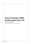
PicoScope 2000 Series
PC Oscilloscopes
User guide
Copyright 2005 Pico Technology Limited. All rights reserved.
PS2000044-1.0
I
PicoScope 2000 Series User Guide
Table of Contents
1 Introduction
.............................................................................................2
1 Overview ...................................................................................................2
...................................................................................................2
2 Safety symbols
...................................................................................................3
3 Safety warning
4 FCC notice...................................................................................................3
5 CE notice ...................................................................................................4
...................................................................................................4
6 Licence conditions
...................................................................................................4
7 Trademarks
8 Warranty ...................................................................................................5
9 Company ...................................................................................................5
details
.............................................................................................6
2 Product information
1 Minimum ...................................................................................................6
system requirements
...................................................................................................7
2 Installation
instructions
...................................................................................................8
3 Specifications
4 Sampling ...................................................................................................8
modes
3 Glossary
Index
.............................................................................................9
......................................................................................................11
Copyright 2005 Pico Technology Limited. All rights reserved.
Introduction
1
Introduction
1.1
Overview
2
The PicoScope 2000 series is a range of low-cost, high-performance PC Oscilloscopes,
fully USB 2.0 capable and backwards compatible with USB 1.1. There is no need for an
additional power supply as power input is from the USB port, so these oscilloscopes are
highly portable.
With the PicoScope software, you can use PicoScope 2000 series oscilloscopes as PC
Oscilloscopes and spectrum analysers; with the PicoLog software, you can use them as
data loggers.
A PicoScope 2000 PC Oscilloscope is supplied with the following items:
USB cable, for use with both types of USB port
Software CD
Quick start guide
Please read the important information in this introductory section and then proceed to the
Installation instructions.
1.2
Safety symbols
Symbol 1: Warning Triangle
This symbol indicates that a safety hazard exists on the indicated connections if
correct precautions are not taken. Ensure that you read all safety documentation
associated with the product before using it.
Symbol 2: Equipotential
This symbol indicates that the outer shells of the indicated BNC connectors are all at
the same potential (shorted together). You must therefore take necessary precautions
to avoid applying a potential across the return connections of the indicated BNC
terminals, as this may result in a large current flow causing damage to the product
and/or connected equipment.
Copyright 2005 Pico Technology Limited. All rights reserved.
PS2000044-1.0
3
1.3
PicoScope 2000 Series User Guide
Safety warning
We strongly recommend that you read the general safety information below before using
your oscilloscope for the first time. Safety protection built in to the equipment may cease
to function if the equipment is used incorrectly. This could cause damage to your
computer, or lead to injury to yourself and others.
Maximum input range
PicoScope 2000 Series PC Oscilloscopes are designed to measure voltages in the range
-20 V to +20 V. Any voltages in excess of ±100 V may cause physical damage.
Mains voltages
Pico Technology products are not designed for use with mains voltages. To measure
mains, use a differential isolating probe specifically designed for a high source voltage.
Safety grounding
PicoScope 2000 Series PC Oscilloscopes connect directly to the ground of a computer
through the interconnecting cable provided. This method minimises interference.
As with most oscilloscopes, avoid connecting the ground input to any source other than
ground. If in doubt, use a meter to check that there is no significant AC or DC voltage
between the ground input of the oscilloscope and the point to which you intend to connect
it. Failure to check may cause damage to your computer, or lead to injury to yourself and
others.
You should assume that the product does not have a protective safety earth.
Repairs
The oscilloscope contains no serviceable parts. Repair or calibration of the oscilloscope
requires specialised test equipment and must be performed only by Pico Technology.
1.4
FCC notice
This equipment has been tested and found to comply with the limits for a Class A digital
device, pursuant to Part 15 of the FCC Rules. These limits are designed to provide
reasonable protection against harmful interference when the equipment is operated in a
commercial environment. This equipment generates, uses, and can radiate radio
frequency energy and, if not installed and used in accordance with the instruction manual,
may cause harmful interference to radio communications. Operation of this equipment in
a residential area is likely to cause harmful interference in which case the user will be
required to correct the interference at his own expense.
For safety and maintenance information see the safety warning.
PS2000044-1.0
Copyright 2005 Pico Technology Limited. All rights reserved.
Introduction
1.5
4
CE notice
The PicoScope 2000 Series of PC Oscilloscopes meets the intent of the EMC directive
89/336/EEC and has been designed to EN61326-1 (1997) Class B Emissions and
Immunity standard.
Products from the PicoScope 2000 series also meet the intent of the Low Voltage
Directive and have been designed to meet the BS EN 61010-1:2001 IEC 61010-1:2001
(safety requirements for electrical equipment, control, and laboratory use) standard.
1.6
Licence conditions
The material contained in this release is licensed, not sold. Pico Technology Limited
grants a licence to the person who installs this software, subject to the conditions listed
below.
Access
The licensee agrees to allow access to this software only to persons who have been
informed of these conditions and agree to abide by them.
Usage
The software in this release is for use only with Pico products or with data collected using
Pico products.
Copyright
Pico Technology Limited claims the copyright of, and retains the rights to, all material
(software, documents etc.) contained in this release. You may copy and distribute the
entire release in its original state, but must not copy individual items within the release
other than for backup purposes.
Liability
Pico Technology and its agents shall not be liable for any loss, damage or injury,
howsoever caused, related to the use of Pico Technology equipment or software, unless
excluded by statute.
Fitness for purpose
Because no two applications are the same, Pico Technology cannot guarantee that its
equipment or software is suitable for a given application. It is your responsibility,
therefore, to ensure that the product is suitable for your application.
Mission-critical applications
This software is intended for use on a computer that may be running other software
products. For this reason, one of the conditions of the licence is that it excludes usage in
mission-critical applications; for example, life-support systems.
1.7
Trademarks
Windows and Excel are registered trademarks or trademarks of Microsoft Corporation in
the USA and other countries.
Pico Technology Limited, PicoLog and PicoScope are trademarks of Pico Technology
Limited, registered in the United Kingdom and other countries.
Copyright 2005 Pico Technology Limited. All rights reserved.
PS2000044-1.0
5
1.8
PicoScope 2000 Series User Guide
Warranty
Pico Technology warrants upon delivery, and for a period of 24 months unless otherwise
stated from the date of delivery, that the Goods will be free from defects in material and
workmanship.
Pico Technology shall not be liable for a breach of the warranty if the defect has been
caused by fair wear and tear, wilful damage, negligence, abnormal working conditions or
failure to follow Pico Technology's spoken or written advice on the storage, installation,
commissioning, use or maintenance of the Goods or (if no advice has been given) good
trade practice; or if the Customer alters or repairs such Goods without the written consent
of Pico Technology.
1.9
Company details
Address:
Pico Technology Limited
The Mill House
Cambridge Street
St Neots
Cambridgeshire
PE19 1QB
United Kingdom
Phone: +44 (0) 1480 396 395
Fax: +44 (0) 1480 396 296
Email:
Technical Support
[email protected]
Sales
[email protected]
Web site:
www.picotech.com
PS2000044-1.0
Copyright 2005 Pico Technology Limited. All rights reserved.
Product information
2
Product information
2.1
Minimum system requirements
6
For PicoScope 2000 series PC Oscilloscopes to operate, a computer with the minimum
system requirements to run Windows or the following (whichever is the higher
specification) is required:
Processor
Pentium class processor or equivalent minimum.
Memory
32 MB minimum.
Disk space
10 MB minimum.
Operating system
Microsoft Windows 98 SE, ME, Microsoft Windows 2000, XP
or later.
Ports
USB 1.1 compliant port minimum. USB 2.0 compliant port
recommended. Must be connected direct to the port or a
powered USB hub. Will not work on a passive hub.
Copyright 2005 Pico Technology Limited. All rights reserved.
PS2000044-1.0
PicoScope 2000 Series User Guide
7
2.2
Installation instructions
Important
Do not connect a PicoScope 2000 series PC Oscilloscope to the PC until you have
installed the software.
Install the software by following the steps in the installation guide supplied with your
oscilloscope.
Connect your oscilloscope to the PC with the USB cable supplied.
There is no need for an additional power supply as power is drawn from the USB port.
Checking the installation
Once the software has been installed, ensure that the oscilloscope is connected to the PC
and start the PicoScope or PicoLog software. The software should now display the
voltage that you have connected. If you are using a scope probe and PicoScope, you
should see a small 50 Hz or 60 Hz mains signal in the oscilloscope window when you
touch the scope probe tip with your finger.
Standard oscilloscope connectors
PicoScope 2000 series PC Oscilloscopes have standard oscilloscope connectors. The
input impedance is also standard, so the x10 function on scope probes works correctly.
Connector diagram
1
2
A
B
USB port connector.
LED. When lit, indicates the oscilloscope is sampling data.
Channel A input.
Channel B input.
PS2000044-1.0
Copyright 2005 Pico Technology Limited. All rights reserved.
Product information
2.3
8
Specifications
PicoScope 2202
Vertical Resolution
8 bits
Analog Bandwidth
2 MHz
Maximum Sampling Rate
Single-channel
Dual-channel
Buffer Size
Single-channel
Dual-channel
Inputs
Voltage Ranges
Accuracy
Operating Environment
Temperature range
Humidity
20 MS/s
10 MS/s
32 ksamples
16 ksamples
2 channels with BNC sockets
1 MW impedance
AC/DC coupling
20 pF input capacitance
± 50 mV to ± 20 V ranges in 1, 2, 5 steps
3 % (voltage)
100 ppm (time)
0°C to 70°C
(20°C to 30°C for quoted accuracy)
25% to 75% RH
± 100 V
Overload Protection
2.4
PC Connection
USB 2.0
Compatible with USB 1.1
Power Supply
From USB port: 4.6 to 5.25 V; 500 mA
External power supply is not required
Maximum Dimensions
140 mm x 190 mm x 45 mm
Compliance
CE standard; FCC standard
Sampling modes
PicoScope 2000 series PC Oscilloscopes can run in various sampling modes. At high
sampling rates, the oscilloscope collects data much faster than a PC can read it. To
compensate for this, the oscilloscope stores a block of data in an internal memory buffer,
delaying transfer to the PC until a preset number of data points has been sampled. This is
called block mode. At very low sampling rates, you may want to switch to streaming
mode. This allows accurately timed data to be transferred back to the PC in short blocks,
without gaps. Real time continuous mode is also provided for use at low sampling
rates, when immediate data transfer without gaps is required but timing accuracy is not
critical.
Copyright 2005 Pico Technology Limited. All rights reserved.
PS2000044-1.0
9
3
PicoScope 2000 Series User Guide
Glossary
AC/DC switch
To switch from alternating current to direct current, or vice versa, select AC or DC from
the control on the oscilloscope toolbar of the PicoScope software application. The setting
should be adjusted to suit the characteristics of the input signal.
Analog bandwidth
The input frequency at which the signal amplitude has fallen by 3 dB from its nominal
value.
Block mode
A sampling mode in which the computer prompts the oscilloscope to collect a block of
data into its internal memory before stopping the oscilloscope and transferring the whole
block into computer memory. This mode of operation is suitable when the input signal
being sampled contains high frequencies. Note: To avoid aliasing effects, the sampling
rate must be greater than twice the maximum input frequency.
Buffer size
The size of the oscilloscope buffer memory. The buffer memory is used by the
oscilloscope to store data temporarily. This allows the oscilloscope to sample data
independently of the speed at which it can transfer data to the computer.
Device Manager
Device Manager is a Windows applet that displays the current hardware configuration of
your computer. On Windows 98 or Windows ME, right click on 'My Computer' and choose
the 'Device Manager' tab. On Windows 2000 or Windows XP, right click on 'My
Computer,' choose the 'Hardware' tab and select 'Device Manager'.
Driver
A software application that controls a piece of hardware. The driver for the PicoScope
2000 series PC Oscilloscopes is supplied in the form of a 32 bit Windows DLL. This is
used by the PicoScope and PicoLog software to control the oscilloscopes.
Maximum sampling rate
A figure indicating the maximum number of samples the oscilloscope is capable of
acquiring per second. Maximum sample rates are usually given in MS/s (megasamples
per second) or GS/s (gigasamples per second.) The higher the sampling speed of the
oscilloscope, the more accurate the representation of the high-frequency details in a fast
signal.
PC Oscilloscope
An instrument consisting of a PicoScope 2000 series PC Oscilloscope and the PicoScope
software application.
PicoLog software
This is a software product that accompanies all our oscilloscopes. It turns your PC into a
data logger and chart recorder.
PicoScope 2000 series
A PC Oscilloscope range that includes the PicoScope 2202 PC Oscilloscope.
PicoScope software
This is a software product that accompanies all our oscilloscopes. It turns your PC into an
oscilloscope, spectrum analyser, and meter display.
PS2000044-1.0
Copyright 2005 Pico Technology Limited. All rights reserved.
Glossary
10
Real time continuous mode
A sampling mode in which the software repeatedly requests single samples from the
oscilloscope. This mode is suitable for low sampling rates when you require the latest
sample to be displayed as soon as it is captured.
Streaming mode
A sampling mode in which the oscilloscope samples data and returns it to the computer in
an unbroken stream. This mode of operation is suitable when the input signal being
sampled contains only low frequencies.
Timebase
The timebase controls the time interval that the width of the scope display represents. If
you select Timebase is time per division in the Preferences dialog box in the PicoScope
application, it works like a traditional bench top scope. There are ten divisions across the
screen, so the total time interval is ten times the timebase.
USB 1.1
Universal Serial Bus (Full Speed). This is a standard port that enables you to connect
external devices to PCs. A typical USB 1.1 port supports a data transfer rate of 12 Mbps
(12 megabits per second), and is much faster than a serial port.
USB 2.0
Universal Serial Bus (High Speed). This is a standard port that enables you to connect
external devices to PCs. A typical USB 2.0 port supports a data transfer rate that is 40
times faster than that supported by USB 1.1. An additional feature of USB 2.0 is that it is
backwards compatible with USB 1.1.
Vertical resolution
A value, in bits, related to the number of distinct input voltage levels that the oscilloscope
can convert to digital values. Calculation techniques can improve the effective resolution.
Voltage range
The range of input voltages that the oscilloscope will measure in a given mode.
Copyright 2005 Pico Technology Limited. All rights reserved.
PS2000044-1.0
11
PicoScope 2000 Series User Guide
PicoScope 2000 series 2, 3, 4, 6, 7
PicoScope software 2, 7
Power supply 8
Probe (oscilloscope) 7
Index
A
Accuracy 8
Analog bandwidth
R
Repair
8
S
B
BNC connector
Buffer size 8
Safety symbols 2
Safety warning 3
Sampling rate (maximum)
Scope probe 7
Spectrum analyser 2
System requirements 6
7
C
Calibration 3
Contact details
5
Data logger
Dimensions
8
T
D
Temperature 8
Test equipment 3
2
8
U
H
Humidity
3
USB 2, 6
USB 1.1 6
USB 2.0 6
8
I
V
Input range (maximum)
Inputs 8
8
Vertical resolution 8
Voltage ranges 8
M
Maximum input range
3
O
Operating environment
Oscilloscope probe 7
Overload protection 8
8
P
PC connection 8
PC oscilloscopes 2, 4
PicoLog software 2
Copyright 2005 Pico Technology Limited. All rights reserved.
Pico Technology Ltd
The Mill House
Cambridge Street
St Neots PE19 1QB
United Kingdom
Tel: +44 (0) 1480 396 395
Fax: +44 (0) 1480 396 296
Web: www.picotech.com
PS2000044-1.0 7.6.05