1
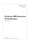
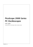
PicoScope 6407
Digitizer
User's Guide
ps6407.en-1
Copyright © 2011 Pico Technology Ltd. All rights reserved.
PicoScope 6407 Digitizer User's Guide
I
Contents
1 Welcome .....................................................................................................................................1
2 Introduction
.....................................................................................................................................2
1 Using this guide
...........................................................................................................................................2
2 Safety symbols
...........................................................................................................................................2
3 Safety warnings
...........................................................................................................................................2
4 FCC notice
...........................................................................................................................................3
5 CE notice
...........................................................................................................................................3
...........................................................................................................................................4
6 Software licence conditions
...........................................................................................................................................5
7 Trademarks
8 Warranty
...........................................................................................................................................5
9 Company details
...........................................................................................................................................5
3 Product information
.....................................................................................................................................6
1 System requirements...........................................................................................................................................6
...........................................................................................................................................7
2 Installation instructions
3 Connections
...........................................................................................................................................8
4 Specifications
...........................................................................................................................................9
4 Glossary .....................................................................................................................................11
Index ..............................................................................................................................................13
Copyright © 2011 Pico Technology Ltd. All rights reserved.
ps6407.en
PicoScope 6407 Digitizer User's Guide
1
1
Welcome
Thank you for buying a PicoScope 6407 Digitizer from
Pico Technology!
This instrument accepts electrical signals in the frequency
range of DC to 1 GHz, samples them at up to 5 GS/s and
converts them to 8-bit digital values. The resulting data can
be used in a wide variety of applications including research
and development, debugging, instrumentation and pass/fail
testing.
The PicoScope 6407 Digitizer has comparable features and
specifications to traditional digitizers, but is more
economical, takes up only a fraction of the space, and its
USB interface removes the need for a specialized
mainframe.
Here are some of the benefits provided by your new PicoScope 6407 Digitizer:
Portability: Take the unit with you and plug it in to any Windows PC.
Performance: Up to 5 GS/s sampling, 1 GHz bandwidth and 1 GS 11 buffer.
Programmability: The PicoScope 6000 Series SDK lets you write your own
programs, in your chosen programming language, to control all the features of the
digitizer.
Long-term support: Software upgrades are available to download from our
website. You can also call our technical specialists for support. You can continue to
use both of these services free of charge for the lifetime of the product.
Value for money: You don't have to pay twice for all the features that you
already have in your PC, as the PicoScope 6407 Digitizer contains the special
hardware you need and nothing more.
Convenience: Your software can make full use of the full-sized display, disk
storage, user interface and networking built in to your PC.
Five-year warranty: Your digitizer is covered for five years from the day of
purchase against manufacturing faults. We don't charge a penny extra for this
benefit.
Copyright © 2011 Pico Technology Ltd. All rights reserved.
ps6407.en
2
Introduction
2
Introduction
2.1
Using this guide
You will sometimes see a symbol like this: 2 This is the cross-reference symbol, and
it indicates the number of a page on which you can find more information about a
topic.
2.2
Safety symbols
The following symbols appear on the front and rear panel of the PicoScope 6407
Digitizer.
Symbol 1: Warning triangle
This symbol indicates that a safety hazard exists on the indicated
connections if correct precautions are not taken. Read all safety
documentation associated with the product before using it.
Symbol 2: Equipotential
This symbol indicates that the outer shells of the indicated SMA (or
BNC on rear panel) connectors are all at the same potential (shorted
together). You must therefore take necessary precautions to avoid
applying a potential across the return connections of the indicated SMA
(or BNC on rear panel) connectors. Such a potential could cause a
large current to flow, resulting in damage to the product or connected
equipment, or both.
2.3
Safety warnings
We strongly recommend that you read the general safety information
below before using your digitizer for the first time. Safety protection
built in to equipment may cease to function if the equipment is used
incorrectly. This could cause damage to your computer, or lead to
injury to yourself and others.
DO NOT exceed the overload protection range. The inputs can withstand a
maximum voltage of ±2 V. Contact with voltages outside the overload protection
range may cause permanent damage to the unit.
DO NOT connect to mains voltages. The product is not designed for use with
mains voltages (also known as line voltages, or house current). To measure mains
voltages, use a differential isolating probe specifically rated for mains use.
DO NOT rely on the scope's ground as a safety ground. The product connects
directly to the ground of a computer through the USB cable provided. This ground is
for signalling and shielding, and is not a safety ground.
DO NOT connect the ground input to any potential other than ground. If in
doubt, use a meter to check that there is no significant AC or DC voltage between the
ground input of the digitizer and the point to which you intend to connect it.
Connecting the ground input to a voltage source may cause damage to the digitizer
and the computer, and injury to yourself and others.
ps6407.en
Copyright © 2011 Pico Technology Ltd. All rights reserved.
PicoScope 6407 Digitizer User's Guide
2.4
3
FCC notice
This equipment has been tested and found to comply with the limits for a Class A
digital device, pursuant to Part 15 of the FCC Rules. These limits are designed to
provide reasonable protection against harmful interference when the equipment is
operated in a commercial environment. This equipment generates, uses, and can
radiate radio frequency energy and, if not installed and used in accordance with the
instruction manual, may cause harmful interference to radio communications.
Operation of this equipment in a residential area is likely to cause harmful interference
in which case the user will be required to correct the interference at his or her own
expense.
For safety and maintenance information see the safety warning
2.5
2
.
CE notice
The product meets the intent of the EMC directive 89/336/EEC and has been
tested to EN61326-1:2006 Class A Emissions and Immunity standard.
The product also meets the intent of the Low Voltage Directive and has been
designed to meet the BS EN 61010-1:2010 IEC 61010-1:2010 Safety
requirements for electrical equipment for measurement, control, and
laboratory use standard.
Copyright © 2011 Pico Technology Ltd. All rights reserved.
ps6407.en
4
2.6
Introduction
Software licence conditions
The material contained in this software release is licensed, not sold. Pico Technology
Limited grants a licence to the person who installs this software, subject to the
conditions listed below.
Access. The licensee agrees to allow access to this software only to persons who
have been informed of these conditions and agree to abide by them.
Usage. The software in this release is for use only with Pico Technology products or
with data collected using Pico Technology products.
Copyright. Pico Technology Ltd. claims the copyright of, and retains the rights to, all
material (software, documents etc.) contained in this release. You may copy and
distribute the PicoScope software and drivers with no modifications, additions or
omissions. You may copy and modify the SDK example programs.
Liability. Pico Technology and its agents shall not be liable for any loss, damage or
injury, howsoever caused, related to the use of Pico Technology equipment or
software, unless excluded by statute.
Fitness for purpose. Because no two applications are the same, Pico Technology
cannot guarantee that its equipment or software is suitable for a given application. It
is your responsibility, therefore, to ensure that the product is suitable for your
application.
Mission-critical applications. This software is intended for use on a computer that
may be running other software products. For this reason, one of the conditions of the
licence is that it excludes usage in mission-critical applications such as life-support
systems.
Viruses. This software was continuously monitored for viruses during production, but
you are responsible for virus-checking the software once it is installed.
Support. If you are dissatisfied with the performance of this software, please contact
our technical support staff, who will try to fix the problem within a reasonable time. If
you are still dissatisfied, please return the product and software to your supplier
within 14 days of purchase for a full refund.
Upgrades. We provide upgrades, free of charge, from our web site at
www.picotech.com. We reserve the right to charge for updates or replacements sent
out on physical media.
ps6407.en
Copyright © 2011 Pico Technology Ltd. All rights reserved.
PicoScope 6407 Digitizer User's Guide
2.7
5
Trademarks
Trademarks. Windows is a trademark of Microsoft Corporation in the United States
and other countries. Pico Technology and PicoScope are internationally registered
trademarks of Pico Technology Ltd.
Pico Technology and PicoScope are trademarks of Pico Technology Limited,
registered in the United Kingdom and other countries.
PicoScope and Pico Technology are registered in the U.S. Patent and Trademark
Office.
2.8
Warranty
Pico Technology warrants upon delivery, and for a period of 5 years from the date of
delivery, that the Goods will be free from defects in material and workmanship.
Pico Technology shall not be liable for a breach of the warranty if the defect has been
caused by fair wear and tear, wilful damage, negligence, abnormal working conditions
or failure to follow Pico Technology's spoken or written advice on the storage,
installation, commissioning, use or maintenance of the Goods or (if no advice has
been given) good trade practice; or if the Customer alters or repairs such Goods
without the written consent of Pico Technology.
2.9
Company details
Address:
Pico Technology
James House
Colmworth Business Park
St. Neots
Cambridgeshire
PE19 8YP
United Kingdom
Phone:
Fax:
+44 (0) 1480 396 395
+44 (0) 1480 396 296
Email:
Technical Support:
Sales:
[email protected]
[email protected]
Web site:
www.picotech.com
Copyright © 2011 Pico Technology Ltd. All rights reserved.
ps6407.en
6
3
Product information
Product information
Using the API functions, you can develop your own programs to collect and analyze
data from the digitizer. Refer to the PicoScope 6000 Series Programmer's Guide for
more information.
Alternatively with the PicoScope software you can use PicoScope 6407 Digitizer as a
high-bandwidth 4-channel oscilloscope.
A PicoScope 6407 Digitizer is supplied with the following items:
USB cable, for use with any standard USB port
Software and Reference CD
Installation Guide
AC adapter and cable
Whilst the above items are included, further accessories are available for purchase, as
detailed below:
TA077 - Attenuator -3dB SMA to SMA
TA078 - Attenuator -6dB SMA to SMA
TA061 - Oscilloscope probe 1.5 GHz, x10, 50 Ω, SMA
3.1
System requirements
To ensure that your PicoScope 6407 Digitizer operates correctly, you must have a
computer with at least the minimum system requirements to run one of the supported
operating systems, as shown in the following table. The performance of the software
will increase with more powerful PCs, including those with multi-core processors.
Item
Operating
system
Specification
Windows XP SP2
Windows Vista
Windows 7
32 bit and 64* bit versions supported
Processor
Memory
Free disk
space
Ports
As required
by Windows
USB 1.1 compliant port, or
USB 2.0 compliant port (recommended)
* While the driver will run on a 64 bit operating system, the driver itself is 32 bit, and
therefore will run as 32 bit.
ps6407.en
Copyright © 2011 Pico Technology Ltd. All rights reserved.
PicoScope 6407 Digitizer User's Guide
3.2
7
Installation instructions
IMPORTANT
Always install the PicoScope software before connecting
your PicoScope 6407 Digitizer 11 to the PC. This ensures
that Windows will correctly recognize the digitizer.
Procedure
Follow the instructions in the 'USB Oscilloscope Quick Start Guide' included with
your product package.
Connect the AC adapter (supplied) to a power socket using the appropriate cable
(also supplied), and connect the DC output of the AC adapter to the "DC Power"
socket on the back of the digitizer.
Connect the digitizer to the PC using the USB cable supplied.
Checking the installation
Once you have installed the software and connected the digitizer to the PC, start the
PicoScope 11 software. PicoScope should now display any signal connected to the
digitizer inputs.
Moving the PicoScope 6407 Digitizer to another USB port
Windows XP SP2 (or later)
When you first installed the digitizer by plugging it into a USB 11 port, Windows
associated the Pico driver with that port. If you later move the digitizer to a different
USB port, Windows will display the "New Hardware Found Wizard" again. When this
occurs, just click "Next" in the wizard to repeat the installation. If Windows gives a
warning about Windows Logo Testing, click "Continue Anyway". As all the software
you need is already installed on your computer, there is no need to insert the Pico
Software CD again.
Windows Vista and Windows 7
The process is automatic. When you move the device from one port to another,
Windows displays an "Installing device driver software" message and then a "
PicoScope 6000 Series oscilloscope" message. The digitizer is then ready for use.
Copyright © 2011 Pico Technology Ltd. All rights reserved.
ps6407.en
8
3.3
Product information
Connections
SMA and BNC Connectors
The PicoScope 6407 Digitizer has SMA connectors on the front panel for the four
channel inputs, and BNC connectors on the rear for the AUX IN and SIGNAL OUT
connections. The channel inputs have an impedance of 50 Ω.
Connector diagrams
Front panel
PicoScope 6407 Digitizer
A.
B.
C.
D.
E.
Input channel A 9
Input channel B 9
Input channel C 9
Input channel D 9
LED: flashes when the digitizer is sampling data
Rear panel
PicoScope 6407 Digitizer
F. DC power socket 10 : for use with the AC adaptor supplied with the unit
G. USB 2.0 port 10 : connects to your PC using the Hi-Speed USB cable supplied
H. SIGNAL OUT connector 9 : carries the output of the arbitrary waveform generator
and signal generator
I. AUX IN connector 9 : carries the auxiliary (AUX) trigger and reference clock
inputs
J. Ventilation holes. Do not block the air intake holes or insert any objects
through them, as this could damage the unit and cause injury.
ps6407.en
Copyright © 2011 Pico Technology Ltd. All rights reserved.
PicoScope 6407 Digitizer User's Guide
3.4
9
Specifications
Model number
Vertical section
Number of channels
Analog bandwidth 11
Rise time (10%-90%)
Connectors
Input coupling 11
Input impedance
VSWR
Voltage ranges 11
Input Sensitivity (x1
zoom)
DC accuracy
Overvoltage protection
Crosstalk
PicoScope 6407 Digitizer
4
1 GHz (-3 dB)
350 ps
SMA female
DC
50 Ω ±2%
< 1.5:1 DC to 1 GHz typical over full bandwidth of scope
±100 mV
20 mV/div (10 divisions) in PicoScope software
3% of full scale
±2 V (DC+ Peak AC)
100:1 DC to 100 MHz
30:1 100MHz to 1 GHz
Acquisition
Vertical resolution 11
8 bits (up to 12 in enhanced resolution mode)
Maximum sampling rate 11 (real-time)
One channel in use
5 GS/s
Two channels in use
2.5 GS/s (when using channels A/C, A/D, B/C, B/D only)
Three or four channels in
1.25 GS/s
use
Maximum streaming data
1 MS/s in PicoScope software, >10 MS/s using supplied SDK (PC-dependent)
rate
Buffer size 11
1 GS
Timebase accuracy
±5 ppm
Triggering
Trigger Modes
Auto, repeat, single, rapid
Basic triggers
Rising, falling,
Advanced triggers
Edge, window, pulse width, window pulse width, dropout, window dropout,
interval, logic, runt pulse
Trigger level
Adjustable over whole of voltage range
Maximum trigger rate
Up to 10,000 waveforms in a 10 ms burst
Re-arm time
Less than 1 µ s on fastest timebase
Trigger sources
Ch A to Ch D, AUX
Maximum trigger delay
Pre-trigger: 100% of capture size
Post-trigger: 4 billion samples
CLOCK/AUX input
Trigger types (AUX input)
Edge, pulse width, dropout, interval, logic, delayed
Input characteristics
Rear panel female BNC, 50 Ω ±1%
Voltage range
±5 V, DC coupled
Bandwidth (AUX input)
25 MHz (-3 dB)
Threshold adjustment
±1 V
range
Overvoltage protection
±5 V
Frequency range (Clock
Reference frequency 5 MHz to 25 MHz
input)
Signal generator and arbitrary waveform generator (AWG)
Connector
BNC female (rear mounted)
Frequency range
DC to 20 MHz
Standard waveforms
Sine, square, triangle, ramp, sin(x)/x,
Gaussian, half-sine, white noise, DC level, PRBS
DAC resolution
12 bits
AWG sample rate
200 MS/s
AWG buffer size
16,384 samples
DC accuracy
1%
Amplitude flatness
<1.5 dB DC to 20 MHz, typical
Amplitude range
±250 mV to ±2 V
Offset adjustment
±1 V (max. combined output ±2.5 V)
Impedance
50 Ω
Overvoltage protection
±5 V
Copyright © 2011 Pico Technology Ltd. All rights reserved.
ps6407.en
10
Product information
Math channels
Functions
–x, x+y, x–y, x*y, x/y, sqrt(x), x^y, exp(x), ln(x), log(x), abs(x), norm(x),
sign(x), sin(x), cos(x), tan(x), arcsin(x), arccos(x), arctan(x), sinh(x), cosh(x),
tanh(x), Pi
A to D (input channels), T (time), reference waveforms
Operands
Mask limit testing
Statistics
Display
Interpolation
Persistence modes
Environmental conditions
Operating environment
Temperature range
Humidity
Fan speed
Storage environment
Temperature range
Humidity
IP rating
Miscellaneous
PC connection
Power supply
Dimensions
Weight
Compliance
Languages supported
(PicoScope only)
ps6407.en
Pass/fail, failure count, total count
Linear or sin(x)/x
Digital color, analog intensity, custom, or none
0 °C to 40 °C operational
20 °C to 30 °C for quoted accuracy
5% to 80% RH, non-condensing
Automatic, to reduce noise
-20 °C to +60 °C
5% to 95% RH, non-condensing
IP 20
Hi-Speed USB 2.0
External AC to 12 V 3.5 A DC adapter and cables (cords) included
170 mm x 255 mm x 40 mm
(6.7" x 10.0" x 1.6")
< 1 kg (approx. 2 lb 3 oz)
Europe: EMC EN61326, LVD EN61010-1, RoHS, WEEE
USA: FCC Rules Part 15 Class A 3
English, Chinese (Traditional and Simplified), Czech, Danish, Dutch, Finnish,
French, German, Greek, Hungarian, Italian, Japanese, Norwegian, Polish,
Portuguese, Romanian, Spanish, Swedish, Turkish
Copyright © 2011 Pico Technology Ltd. All rights reserved.
PicoScope 6407 Digitizer User's Guide
4
11
Glossary
Analog bandwidth. The input frequency at which the measured signal amplitude is
3 decibels below the true signal amplitude.
Buffer size. The size of the oscilloscope/digitizer buffer memory, measured in
samples. The buffer allows the digitizer to sample data faster than it can transfer it to
the computer.
Device Manager. Device Manager is a Windows program that displays the current
hardware configuration of your computer. Right-click on "My Computer", select
"Manage" and then select "Device Manager".
Driver. A program that controls a piece of hardware. The driver for the oscilloscope/
digitizer is supplied in the form of a 32-bit Windows DLL, ps6000.dll. This is used
by the PicoScope software, and by user-designed applications, to control the digitizer.
GS. Gigasamples (1,000,000,000 samples).
Maximum sampling rate. A figure indicating the maximum number of samples the
oscilloscope/digitizer can acquire per second. The higher the sampling rate of the
device, the more accurate the representation of the high-frequency details in a fast
signal.
MS. Megasamples (1,000,000 samples).
PC Digitizer. A virtual instrument formed by connecting a PicoScope oscilloscope/
digitizer to a computer running a custom application or the PicoScope software.
PicoScope 6000 Series. A range of 8-bit USB oscilloscopes and digitizers from Pico
Technology, with a sampling rate of 5 GS/s, a bandwidth of 350 MHz to 1 GHz and
buffer sizes up to 1 GS.
PicoScope software. A software product that accompanies all PicoScope
oscilloscopes and digitizers. It turns your PC into an oscilloscope, digitizer, and
spectrum analyzer.
USB 2.0. Universal Serial Bus. This is a standard port used to connect external
devices to PCs. The port supports a data transfer rate of up to 480 megabits per
second, so is much faster than the RS-232 COM ports found on older PCs.
Vertical resolution. A value, in bits, indicating the precision with which the
oscilloscope/digitizer converts input voltages to digital values. Software enhancement
can improve the effective vertical resolution.
Voltage range. The range of input voltages that the oscilloscope/digitizer can
measure. For example, a voltage range of ±100 mV means that the oscilloscope/
digitizer can measure voltages between -100 mV and +100 mV. Input voltages
outside this range will not damage the instrument as long as they remain within the
protection limits stated in the Specifications 9 table.
Copyright © 2011 Pico Technology Ltd. All rights reserved.
ps6407.en
PicoScope 6407 Digitizer User's Guide
Index
M
Mains voltages
A
Accuracy 9
Analog bandwidth
9
Operating environment
Operating system 6
Outputs 9
Overvoltage protection
9
9
5
R
D
Resolution, vertical
Dimensions 9
Disk space 6
S
E
Safety
symbols
warning
EMC Directive 3
External trigger 8
2
2
Software license conditions
Specifications 9
Storage environment 9
System memory 6
System requirements 6
3
G
2
4
T
I
Input range, maximum
Inputs 9
Installation 7
9
Sampling rate 9
Signal generator 9
output 8
F
Grounding
9
PC connection 9
Pico Technical Support 5
PicoScope 6000 Series 1
PicoScope software 7
Power socket 8
Power supply 9
Processor 6
Product information 6
CE notice 3
Company information 5
Compliance 9
Connections
BNC connector 8
SMA connector 8
FCC notice
9
P
C
Contact details
Crosstalk 9
2
O
B
Bandwidth
Buffer size
13
Technical support 5
Trademarks 5
Trigger
bandwidth 9
external 8, 9
9
L
LED 8
Low Voltage Directive (LVD)
U
3
Copyright © 2011 Pico Technology Ltd. All rights reserved.
USB 6
changing ports
7
ps6407.en
14
Index
V
Vertical resolution 9
Voltage ranges 9
W
Warning triangle 2
Warranty 5
Weight 9
Windows, Microsoft 6
ps6407.en
Copyright © 2011 Pico Technology Ltd. All rights reserved.
PicoScope 6407 Digitizer User's Guide
Copyright © 2011 Pico Technology Ltd. All rights reserved.
15
ps6407.en
Pico Technology
James House
Colmworth Business Park
ST. NEOTS
Cambridgeshire
PE19 8YP
United Kingdom
Tel: +44 (0) 1480 396 395
Fax: +44 (0) 1480 396 296
www.picotech.com
ps6407.en-1
18.04.11
Copyright © 2011 Pico Technology Ltd. All rights reserved.