1
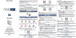
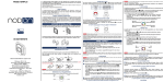
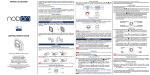
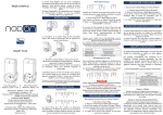
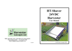
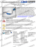
USER GUIDE
The NodOn® wall switch can be added and operated in any Z-Wave® network
with other Z-Wave® certified devices from other manufacturers and/or other
applications.
All non-battery operated nodes within the network will act as repeaters regardless of vendor to increase reliability
of the network.
WALL SWITCH INTERFACE
The wall switch has 4 buttons and one LED located on the top of the product.
LED
Button
Button
Button
Button
It has 2 distinctive working modes:
1. «STANDALONE» MODE
The wall switch can control Z-Wave® compatible devices directly, such as the
NodOn® Smart Plug or a light dimmer, whoever is the manufacturer.
Note: No home automation gateway is involved and necessary in this mode.
2. «GATEWAY» MODE
The wall switch is in “Gateway” Mode as soon as it is added in a Z-Wave® network
managed by a home automation gateway. The wall switch becomes then the
gateway’s assistant, capable to launch up to 16 different scenes through it (SCENE
Profile) or directly associated to your Z-Wave® compatible devices (MONO or DUO
Profile).
BATTERY LEVEL
In order to know the battery level, a simultaneous short press on 1 and 2 must
be performed. The LED will display the battery level according to below table:
LED state
Green
Orange
Red
Battery level
Above 50%
Between 50 and 20%
Below 20%
INSTALLATION
The wall switch can be screwed (screws not included) or bonded thanks of the
adhesive tape included.
FACTORY RESET
A factory reset will completely delete the memory of the wall switch and restore all
the parameters to default value.
A simultaneous long press (1sec) on 3 and 4 will perform this factory reset.
When you put in place your wall switch on a plane surface, make sure that the
battery holder is on the bottom part.
WALL SWITCH
The LED will blink red and green to validate the reset
USAGE
PUTTING INTO SERVICE
For the first application, take care to remove the battery protector.
Wall switch NodOn®
Reference: CWS-3-1-0x
Power supply: CR2032 battery
Radio frequency: 868MHz
Range up to 80 meters outdoor
Range up to 40 meters indoor
Operational temperature: 0°C / 40°C
IP20
Radio protocol: Z-Wave Plus® (500 series)
Dimensions: 80 mm (L) x 80 mm (l) x 15 mm (h)
Weight: 52 g
Warranty: 2 years
BATTERY CHANGE
The wall switch NodOn® works thanks to a CR2032 battery (included).
In order to change the battery, detach the frame of the wall switch and pull out
then the two buttons from their support.
Or
Slide the battery with your thumb without pull on the battery contact holding the
battery.
Careful : If you pull too much on the battery contact in order to change the battery,
you risk to break it.
Careful : In “Standalone” Mode, make sure to remove all the devices added or associated in the wall switch’s
network before performing a factory reset.
In “Gateway” Mode, use the factory reset procedure only when the Primary Controller (i.e. the gateway) is missing
or defective. Reset the wall switch does not mean that it has been removed from the Primary Controller memory.
Remove the wall switch (through the Primary Controller) before performing a factory reset.
« STANDALONE » MODE
By default, the wall switch is in “Standalone” Mode. It means it can control
compatible Z-Wave® devices without involving the gateway. The wall switch acts
as the Primary Controller of the network.
While the wall switch is in “Standalone” Mode, you can:
•Control one or several devices (up to 8) with only 1 button: MONO Profile.
•Control one or several devices (up to 8) with 2 buttons: DUO Profile.
Careful : You must not unplug a Z-Wave® device definitely without removing it from the wall switch’s Z-Wave®
network first (See the “Exclusion” part below). This can have a serious impact on the battery lifetime.
ASSOCIATION
Careful : Before associating a device which was not recently bought, please perform an ”EXCLUSION” first. Please
refer to the “Exclusion” section below.
Association is performed in 3 steps:
1 Push 3 times (quickly) on the 1 button to activate the “Association” Mode.
The LED glows in blue
2 Choose which button will control your device, within 10 seconds.
• A short press on one of the buttons of the wall switch (1, 2, 3 or
4) will activate the MONO Profile. The pressed button will then control
your device.
• A long press on the 1 button will activate the DUO Profile, combined
with the 3 button. The 1 (ON) and 3 (OFF) buttons will then control
your device.
• A long press on the 2 button will activate the DUO profile, combined
with the 4 button. The 2 (ON) and 4 (OFF) buttons will then control
your device.
The LED blinks in blue to confirm your choice
3 Place the device you want to associate in “Learning” Mode, within 10 seconds.
To do so, please refer to your device’s user guide.
The LED of the wall switch blinks green to confirm the association process
Careful : In case of a too long association process or others problems during the process, the LED will blink red.
Please restart the procedure.
Once the association is validated, your wall switch is able to control your device.
Different actions are possible.
1. MONO PROFILE
This profile allows controlling your associated device(s) using just a single button
of the wall switch.
A short press on 1, 2, 3 or 4 (depending on your choice during association
process) will activate (ON) your associated device(s), a second short press will
deactivate (OFF) your associated device(s).
If your device has dimming features (light dimmer, roller shutter, etc.):
• A long press on the 1, 2, 3 or 4 (depending on your choice during
association process) will dim up your associated device (light, roller
shutter, etc.) until you release the button.
• A second long press on the same button will dim down your associated
device (light, roller shutter, etc.) until you release the button.
ON & OFF
Up & Down
ON & OFF
Up & Down
Up & Down
ON & OFF
Up & Down
ON & OFF
2. DUO PROFILE
This profile allows controlling your associated device(s) with two mutual buttons.
• A short press on 1 (or 2 depending on your combination choice during
association process) will activate (ON) your associated device(s).
• A short press on 3 (or 4 depending on your combination choice during
association process) will deactivate (OFF) your associated device(s).
If your associated device(s) has dimming features (light dimmer, roller shutter, etc.):
• A long press on 1 (or 2 depending on your combination choice during
association process) will dim up your associated device (light, roller
shutter, etc.) until you release the button.
• A long press on 3 (or 4 depending on your combination choice during
association process) will dim down your associated device (light, roller
shutter, etc.) until you release the button.
ON
Up
Down
OFF
ON
Up
Down
OFF
Carful : It is not possible to cumulate a MONO and DUO profile on the same button.
Repeat the association process as many times as you want to associate a new
device.
DISASSOCIATION
The disassociation deletes any association relationship between the device and
the wall switch’s buttons. However, your device will remain in your wall switch’s
Z-Wave® network.
1 Push 3 times (quickly) on the 2 button.
The LED blinks in blue
2 Place the device you want to disassociate in “Learning” Mode, within 10
seconds. To do so, please refer to your device’s user guide.
The LED blinks in green to confirm the disassociation
INCLUSION
Inclusion allows adding a device into the wall switch’s Z-Wave® network, without
associating it with any buttons of the wall switch. The wall switch will then not be
able to control your added device.
1 Push 3 times (quickly) on the 3 button.
The LED blinks in blue
2 Place the device you want to add in “Learning” Mode, within 10 seconds. To do
so, please refer to your device’s user guide.
The LED blinks in green to confirm the inclusion
EXCLUSION
Exclusion allows removing your device from the wall switch’s Z-Wave® network.
1 Push 3 times (quickly) on the 4 button.
The LED blinks in blue
2 Place the device you want to remove in “Learning” Mode, within 10 seconds. To
do so, please refer to your device’s user guide.
The LED blinks in green to confirm the exclusion
« GATEWAY» MODE
When the wall switch NodOn® is in “Gateway” Mode, it only communicates with
the home automation gateway, in order to launch scenes when the buttons are
pressed.
However, if your home automation gateway does not support scenes features,
it is still possible to create direct association between the wall switch and the
compatible devices you want to control, through configuration parameters and
association groups.
Nonetheless, if supported, it is strongly advised to use scenes, in order to enjoy the
best experience and increase the battery lifetime.
In order to put your wall switch into “Gateway” Mode, you just have to add the wall
switch into the gateway’s Z-Wave® network. Procedure as following:
1 Place your home automation gateway into “Inclusion” Mode. To do so, please
refer to your gateway’s user guide.
2 Simultaneously push on 1 and 2, during 1sec.
The LED glows in pink to confirm the selection
3 Push on 1, within 10 seconds.
The LED blinks in pink to confirm your choice
The LED blinks in green to confirm the procedure
Warning : If your wall switch added some devices in “Standalone” Mode, these devices will remain orphans. Make
sure you remove (or reset) all devices previously added or associated into the wall switch’s network, before placing
the wall switch in “Gateway” Mode.
If your home automation gateway supports the “ Controller shift” feature, you can
recover the existing wall switch’s network (while it is in “Standalone” Mode) when
you pass into “Gateway” Mode.
Your home automation gateway will be added into the wall switch’s network, and
set as the main controller. All the information related to the added devices will
be automatically copied to the home automation gateway during this process.
However, all existing association between the wall switch and devices will be
lost, and would need to be set-up again, using your home automation gateway
interface.
The existing network of the gateway will be lost as well.
The procedure is as following:
1 Place your home automation gateway into “Learning” Mode. To do so, please
refer to your gateway’s user guide.
2 Simultaneously push on 1 and 2, during 1sec.
The LED glows in pink to confirm the selection
3 Push on 2, within 10 seconds.
The LED blinks in pink to confirm your choice
The LED blinks in green to confirm the procedure
REMOVE THE WALL SWITCH FROM THE NETWORK
In order to remove the wall switch from the gateway’s Z-Wave® network:
1 Place your gateway into “Exclusion” Mode. To do so, please refer to your
gateway’s user guide.
2 Simultaneously push on 1 and 2, during 1sec.
The LED glows in pink to confirm the selection
3 Push on 1, within 10 seconds.
The LED blinks in pink to confirm your choice
The LED blinks in green to confirm the procedure
Expert Note: It is possible to send just a single NIF by following this procedure:
1 Simultaneously push on 1 and 2, during 1sec
1
2
MONO
DUO
The LED glows in pink to confirm the selection
SCENE TYPE
2 Push on 3, within 10 seconds
The LED blinks in pink to confirm your choice
“GATEWAY MODE” FEATURES
Warning : Make sure your gateway supports all the features of the wall switch (compatible gateways are listed on
www.nodon.fr/en ).
INCLUSION ON BEHALF OF THE GATEWAY
1 Push 3 times (quickly) on the 1 button.
The LED blinks in blue
2 Place the device you want to add in “Learning” Mode, within 10 seconds. To do
so, please refer to your device’s user guide.
The LED blinks in green to confirm the inclusion
EXCLUSION ON BEHALF OF THE GATEWAY
1 Push 3 times (quickly) on the 4 button.
The LED blinks in blue
2 Place the device you want to remove in “Learning” Mode, within 10 seconds. To
do so, please refer to your device’s user guide.
The LED blinks in green to confirm the exclusion
ASSOCIATION GROUPS
Once set-up through the gateway, association groups allow direct communication
between the wall switch and the Z-Wave® devices you want to control, without
involving the gateway in the communication.
The wall switch has 7 associations groups:
Group
1
2
3
4
5
6
7
Group Name
Lifeline
Button 1 - Mono - Controlled nodes
Button 2 - Mono - Controlled nodes
Button 3 - Mono - Controlled nodes
Button 4 - Mono - Controlled nodes
Button 1&3 - Duo - Controlled nodes
Button 2&4 - Duo - Controlled nodes
Group 1 – Lifeline
Maximum number of devices in group: 1
This group is dedicated for the home automation gateway.
Group 2/3/4/5
Maximum number of devices in group: 8
Devices associated in these groups are controlled by the corresponding button,
according to MONO Profile (in the exact same way as « Standalone » Mode).
Group 6/7
Maximum number of devices in group: 8
Devices associated in these groups are controlled by the corresponding buttons,
according to DUO Profile (in the exact same way as « Standalone » Mode).
CONFIGURATION PARAMETERS
Buttons’ profile (MONO/DUO/SCENE), in « Gateway » Mode, are set-up through
several configuration parameters.
BUTTONS 1&3 PROFILE
Parameter Number
Default Value
1
0
To set-up the profile of buttons 1 & 3
Value
Description
0
SCENE
1
MONO
2
DUO
Size
1 [byte]
BUTTONS 2&4 PROFILE
Parameter Number
Default Value
2
0
To set-up the profile of buttons 2 & 4
Value
Description
0
SCENE
Size
1 [byte]
Parameter Number
Default Value
Size
3
0
1 [byte]
To choose the way of sending Scene to the gateway
Value
Description
0
CENTRAL SCENE
1
SCENE ACTIVATION
We strongly advise you to use « CENTRAL SCENE », which is more user-friendly.
However, some home automation gateways don’t support « CENTRAL SCENE »
yet, then you can still use the previous standard « SCENE ACTIVATION ».
The user interface of your gateway will then allow you to set-up scenes.
BUTTON 1 CONFIGURATION
Parameter Number
Default Value
Size
4
0
1 [byte]
To set-up the how button 1 behaves, when set in MONO Profile
Value
Description
0
Control Group 2
1
All Switch ON
2
All Switch OFF
BUTTON 2 CONFIGURATION
Parameter Number
Default Value
Size
5
0
1 [byte]
To set-up the how button 2 behaves, when set in MONO Profile
Value
Description
0
Control Group 3
1
All Switch ON
2
All Switch OFF
BUTTON 3 CONFIGURATION
Parameter Number
Default Value
Size
6
0
1 [byte]
To set-up the how button 3 behaves, when set in MONO Profile
Value
Description
0
Control Group 4
1
All Switch ON
2
All Switch OFF
BUTTON 4 CONFIGURATION
Parameter Number
Default Value
Size
7
0
1 [byte]
To set-up the how button 4 behaves, when set in MONO Profile
Value
Description
0
Control Group 5
1
All Switch ON
2
All Switch OFF
When the selected profile is « SCENE » (default value), the wall switch
communicates only with the home automation gateway. The user interface of your
gateway will then allow you to set-up scenes based on which (and which way) you
press the different buttons. To do so, please refer to your gateway’s user guide.
The different actions that can be handled by the wall switch are:
• Simple press (on 1, 2, 3 or 4)
• Double press (on 1, 2, 3 or 4)
• Long press (on 1, 2, 3 or 4)
• Button released (on 1, 2, 3 or 4)
Which makes a total of 16 different actions.
It is strongly advised to use this profile if supported by your gateway.
However, if your home automation gateway does not support these features, you
can still use association groups and set-up your buttons as
• MONO Profile, to control the corresponding group or activate the
Z-Wave® « All Switch ON » or « All Switch OFF » features.
• DUO Profile, to control the corresponding groups.
LED MANAGEMENT
Parameter Number
8
Default Value
0
How to set up LED behaviour
Size
1 [byte]
Value
Description
0
No LED
1
Flash Blue after button press
2
Blinking to confirm command
3
Both options above (1&2)
Warning : In order that the wall switch takes into account the update of association groups and/or configuration
parameters just modified through your home automation gateway, it is necessary to wake it up. To do so, press on any
button of the wall switch. The new associations and/or configuration parameters will be then effective.
COMMAND CLASS
The wall switch supports the following Command Class:
COMMAND CLASS
VERSION
All switch*
V1
Application status*
V1
Association
V2
Association Group Information
V1
Basic*
V1
Battery
V1
Central Scene**
V2
Configuration
V1
Device Reset Locally
V1
Manufacturer Specific
V2
Multilevel Switch*
V3
Power Level
V1
Scene Activation*
V1
Version
V2
Wake-Up**
V2
V2
Z-Wave® Plus info**
* Controlled only (not supported)
** Controlled AND supported
DECLARATION OF CONFORMITY
EN 60950-1:2006 +A11:2009 + A1:2010 + A12:2011 + A2:2013
EN 300 220-2 V2.4.1:
EN301 489-1 V1.9.2 & EN301 489-3 V1.6.1
EN 62479:2010
LOGOTYPE
This product is compliant with all relevant European standards.
When sorting your waste, please observe the disposal regulations in
force. Please place your waste in the facilities provided for that purpose
and with all due respect for the environment.
This product must be used indoor only.
This product is compatible with Z-Wave® and Z-Wave Plus®
protocol.
CONTACT
NodOn® by ID-RF:
ID-RF SAS
121 rue des Hêtres
45590 St CYR EN VAL (FRANCE)
AFTER SALES
www.nodon.fr section “support”
[email protected]
For user guides in other languages, please visit
www.nodon.fr/notices