1
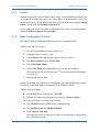
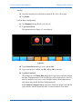
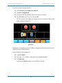
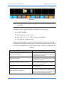
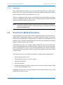
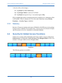
Lake Contour Designer Mode Manual
Release Date: August 2003
Document Version: 1.1
Part Number: DOC-532-0012
www.contour.lake.com
Important Safety Instructions and Warnings
Standards Compliance
This product has been certified to comply with:
•
Safety
UL6500, EN 60065, CB scheme.
•
EMC
FCC part 15 Class A
And carries the CSA mark and FCC required marking.
NOTE: This equipment has been tested and found to comply with the limits for a Class
A digital device, pursuant to Part 15 of the FCC Rules. These limits are designed to provide reasonable protection against harmful interference when the
equipment is operated in a commercial environment. This equipment generates, uses, and can radiate radio frequency energy and, if not installed and
used in accordance with the instruction manual, may cause harmful interference to radio communications. Operation of this equipment in a residential
area is likely to cause harmful interference in which case the user will be required to correct the interference at his own expense.
Explanation of Symbols
These symbols are internationally accepted symbols that warn of potential hazards with
electrical products.
The lightning flash in an equilateral triangle alerts the user to the presence of uninsulated “dangerous voltage” within the product enclosure
that may be of sufficient magnitude to constitute a risk of electric shock.
The exclamation mark in an equilateral triangle alerts the user to the presence of important safety, operating or maintenance (servicing) instructions in the literature accompanying the appliance.
Safety Instructions
1.
Read these instructions.
2.
Keep these instructions.
3.
Heed all warnings.
4.
Follow all instructions.
5.
Do not use this apparatus near water.
6.
WARNING! To reduce the risk of fire or electric shock, do not expose this apparatus to rain or moisture.
7.
Clean only with dry cloth.
8.
Do not block any ventilation openings. Install in accordance with the manufacturer’s instructions.
9.
Do not install near any heat sources such as radiators, heat registers, stoves, or
other apparatus (including amplifiers) that produce heat.
10. Warning! This is a Class 1 device. The electrical safety design of Class 1 devices depends on proper grounding. To maintain electrical safety ensure that a
grounded mains lead is used and that it is properly connected to a grounded
mains wall outlet.
11. Do not defeat the safety purpose of the polarized or grounding-type plug. A polarized plug has two blades with one wider than the other. A grounding type
plug has two blades and a third grounding prong. The wide blade or the third
prong are provided for your safety. If the provided plug does not fit into your
outlet, consult an electrician for replacement of the obsolete outlet.
12. Protect the power cord from being walked on or pinched particularly at plugs,
convenience receptacles, and the point where they exit from the apparatus.
13. Only use attachments/accessories specified by the manufacturer.
14. Unplug this apparatus during lightning storms or when unused for long periods
of time.
15. WARNING! Refer all servicing to qualified service personnel. Servicing is required when the apparatus has been damaged in any way, such as power-supply
cord or plug is damaged, liquid has been spilled or objects have fallen into the
apparatus, the apparatus has been exposed to rain or moisture, does not operate
normally, or has been dropped.
16. WARNING! To reduce the risk of electric shock, DO NOT REMOVE COVER.
No user serviceable parts inside.
Clair iO Designer Mode Manual
Table of Contents
Chapter 1: Introduction to Designer Mode ...........................................................7
1.1
Security Levels ..........................................................................................7
1.1.1
1.1.2
1.1.3
1.2
Designer Mode ..........................................................................................8
1.2.1
1.2.2
1.3
Global..........................................................................................7
Module ........................................................................................7
Base Configuration .....................................................................8
Password Protection of Designer Mode......................................8
Simple Designer Mode System Security ....................................9
Designing and Protecting a Contour System.............................................9
1.3.1
System Setup for Designer Mode Tutorial .................................9
Chapter 2: Designer Mode Security .......................................................................11
2.1
Security for the Base Configuration ........................................................11
2.1.1
2.1.2
2.1.3
2.1.4
2.1.5
2.2
Security for Module Functions................................................................16
2.2.1
2.2.2
2.3
Module Tutorial ........................................................................17
Summary ...................................................................................18
Security for Group Functions ..................................................................19
2.3.1
2.3.2
2.4
Crossover and Output EQ .........................................................11
PEQ and GEQ ...........................................................................11
Levels ........................................................................................12
Base Configuration Tutorial......................................................12
Summary ...................................................................................16
Group Tutorial...........................................................................19
Summary ...................................................................................20
Security for Global Access Functions .....................................................20
2.4.1
2.4.2
Global Access Tutorial..............................................................21
Summary ...................................................................................21
Chapter 3: Designer Mode Quick Reference .....................................................23
3.1
Crossover Functions ................................................................................23
iv
Clair iO Designer Mode Manual
3.1.1
3.1.2
3.2
EQ Functions ...........................................................................................24
3.2.1
3.2.2
3.3
Set Hide/View Only Status for an Individual EQ Overlay .......24
Set Hide/View Only Status for All EQ Overlays......................24
Levels Functions......................................................................................24
3.3.1
3.3.2
3.3.3
3.3.4
3.3.5
3.3.6
3.4
Set Hide/View Only Status for an Individual Crossover ..........23
Set Hide/View Only Status for All Crossover Pages................23
Invert Polarity of an Output Channel........................................24
Restrict Level Adjustments.......................................................25
Disable Level Adjustments .......................................................26
Disable Access to a Levels Function ........................................26
Disable/Enable Unused Output Channels .................................27
Set Hide/View Only Status for All Levels Pages .....................27
Additional Designer Mode Functions .....................................................27
3.4.1
3.4.2
3.4.3
3.4.4
Switch between Designer and User Mode ................................27
Lock and Password-Protect a Module or Base Configuration..28
Unlock a Locked Module or Base Configuration .....................28
Properties Page Designer Mode Features .................................28
v
Clair iO Designer Mode Manual
Chapter 1: Introduction to Designer Mode
The Lake Contour Controller software provides two modes of operation: User and Designer Mode. This manual describes the Designer Mode and should be used in conjunction with the Lake Contour User Mode Manual.
The important functions that Designer Mode activates include:
•
Global Access Security
•
Overlay Access Security
•
Level Limits
•
Factory Settings
•
Password Protection of Modules and Base Configurations
This document provides detailed descriptions of these functions. An example system
design illustrates the utility of Designer Mode functions. A quick reference guide provides a high level overview of Designer Mode functions.
We recommend reading the Lake Contour User Mode Manual before reading this
document.
1.1
Security Levels
Designer Mode provides three levels of password-protected security that can be applied
to a Contour system configuration.
1.1.1
Global
At the Global level, a simple selection makes system-wide changes that affect what can
be seen or adjusted in User Mode. A system designer can choose to hide any combination of EQ Overlays, Crossover tabs, levels, and meters. These items can also be set to
View Only, allowing a User Mode operator to view, but not change the specified item.
NOTE: Global settings are saved in the system configuration file.
1.1.2
Module
Individual EQ Overlays and Crossover tabs can be hidden or set to View Only. Additional
settings normally invisible in User Mode can also be adjusted and hidden at Module level.
At the Module level, changes are specific to individual Modules and Groups. Discrete
password protection can be applied to Modules, providing an additional level of security.
7
Clair iO Designer Mode ManualIntroduction to Designer Mode
1.1.3
Base Configuration
Base Configuration is the lowest level of security, enabling the system designer to define an underlying base EQ curve and crossover settings along with factory levels and
level limits. A system designer can restrict what can be seen or adjusted and provide
optional password protection to the underlying settings.
1.2
Designer Mode
The functions available in Designer Mode can be used with or without password protection. By default, the Designer Mode password is empty, allowing unprotected access
to Designer Mode in a new installation of the Contour Controller software.
To access Designer Mode:
1.
From the Home level, tap User Preferences.
2.
Tap Designer Mode.
Additional buttons on the button bar become active, providing functions specific to Designer Mode as shown in Figure 1-1.
Figure 1-1
1.2.1
Password Protection of Designer Mode
Each software installation has one Designer Mode password. This password is stored
on the host computer and is relevant for any system configuration.
To password-protect Designer Mode:
1.
Tap the Change Password button.
2.
Enter a password and tap OK.
3.
Confirm the password and tap OK.
It is important that you record the Designer Mode password in a safe place. Once the
password is set, it will always be required to enter Designer Mode.
8
Clair iO Designer Mode ManualIntroduction to Designer Mode
1.2.2
Simple Designer Mode System Security
If multiple levels of security are not required for your Contour Controller installation,
exiting Designer Mode activates all security features described in this document without
needing to lock or password-protect individual Modules or Base Configuration files.
1.3
Designing and Protecting a Contour System
This section discusses how to use Designer Mode to protect your system by developing
an example system with one hardware processor. The example includes explicit instructions to define a Base Configuration, lock individual Module level settings, and
enforce Global security.
NOTE: You must have properly networked the Contour Processor and the Contour
Controller host computer. Refer to the Lake Contour User Mode Manual if you
have not completed this yet.
1.3.1
System Setup for Designer Mode Tutorial
Follow the steps below to prepare for the tutorial:
Access Designer Mode:
1.
Double Tap the Contour Controller icon to open the software.
2.
Tap No when asked whether to recall last configuration.
3.
If a keyboard appears requesting a password, enter your Designer Mode password and go to step 6. Otherwise, tap User Preferences.
4.
If the Designer Mode button is blue, tap Designer Mode and enter your Designer Mode password if prompted.
If the Designer Mode button is orange, you are already logged in to Designer
Mode.
5.
Tap Home to return to the main menu.
Place both Modules of the Contour Processor in the work area:
6.
Tap Modules.
7.
Tap Module A on the Scrollbar and tap again in the work area.
The Contour Controller synchronizes with the Processor.
8.
Tap Module B on the Scrollbar and tap again in the work area.
9
Clair iO Designer Mode ManualIntroduction to Designer Mode
Load a 3-way configuration into both Modules:
9.
Tap the Module A icon to select it.
10. Tap Module Store/Recall.
11. Select the Default Modules folder on the Scrollbar and tap Open.
12. Select the Default 3 Way Module from the Scrollbar and tap Recall.
13. Tap Module B to select it, select Default 3 Way Module, and tap Recall.
Label the frame and save the system:
14. Tap Store/Recall Exit then tap Label & Lock.
15. Tap Label Frame, enter LAKE as the frame name, and tap OK.
16. Tap Home then System Store/Recall.
17. Navigate to, or create a folder in which to store the file.
18. Tap New Store, enter the filename as Designer Mode Tutorial, and tap OK.
Your system configuration is now ready for the following tutorials.
10
Clair iO Designer Mode Manual
Chapter 2: Designer Mode Security
2.1
Security for the Base Configuration
A Base Configuration file contains Crossover, EQ, and Levels information for a particular speaker type. A Base Configuration file can be used to create a standard starting
point for a particular make and model of speaker; this can then be used in a variety of
system configurations and fine-tuned using Module and Group settings.
The Base password is saved with the Base Configuration file, and is stored at the hardware level when loaded into a Contour processor. This prevents access to certain data
stored in the Base Configuration file, even if you are in Designer Mode in the Contour
Controller. Using a Base password allows hiding of your custom settings from any of
user of the Contour system.
2.1.1
Crossover and Output EQ
All information in the XOVER screen is stored in the Base Configuration file, including
crossover frequencies, crossover type (i.e., Bessel, Butterworth, or Linkwitz/Riley)
along with any output-specific EQ, high pass filter, and crossover access status. All data
in the XOVER screen can be adjusted for each Module, unless the designer has applied
security to the Base Configuration file. See Section 3.4.2 on page 28 for further information on locking a Base Configuration file.
A Base Configuration file cannot be loaded into a Module running a different DSP program. For example, a 2-way Base Configuration file cannot be loaded into a Module
that is currently running a 3-way program; a 2-way Module program must be loaded
first.
2.1.2
PEQ and GEQ
All Module and Group EQ Overlays are combined and stored as an invisible default EQ
curve for the new Base Configuration. This default EQ curve cannot be viewed or adjusted, although further EQ Overlays can be created at the Module or Group level. When
the new Base Configuration file is loaded into a different Module, the main EQ appears
flat. Output-specific EQ from the XOVER or Output EQ screens can still be viewed or
adjusted, unless the system designer has protected it.
NOTE: The EQ curve created in the PEQ and GEQ Overlays is separate from any
output-specific EQ created on the XOVER page.
11
Clair iO Designer Mode Manual
2.1.3
Designer Mode Security
Levels
With the exception of Limiter and Soft Clamp Corners, current Module and Group Levels
are combined and stored as factory levels when a Base Configuration file is saved. The
factory levels can be viewed and adjusted in Designer Mode after activating the Adjust
Factory option in the Levels/Meter Options menu.
Level Limits, also stored with a Base Configuration file, can be viewed and adjusted
from Levels/Meter Options->Levels Limits.
2.1.4
Base Configuration Tutorial
This tutorial illustrates important features about Base Configuration files.
Adjust Levels and Level Limits:
1.
Navigate to the Gain levels page of Module A.
2.
Adjust the Output 2 gain to -9 dB.
3.
Tap the Delay button and increase Output 3 delay to 6.00 ms.
4.
Tap Meter Options then tap Level Limits.
5.
Select Gain/Delay Limits.
6.
Tap the Max Delay value highlighted in blue for the Input channel.
This is located on the left of the screen, 2nd from bottom and should initially
read 1800.00
7.
Enter 0 (zero) and tap OK.
Setting a maximum value identical to the minimum value removes the fader when in
User Mode, or when the Base Configuration file or Module is locked.
Adjust Crossover Settings:
8.
Tap the EQ tab (top-left) and select XOVER.
9.
With the first output (low frequency) selected, tap Crossover Select.
10. Select 36dB Butterworth from the Scrollbar.
11. Tap XOVER Set then tap YES to the warning message.
12. Tap XOVER Access then High Pass Enable.
13. Tap Crossover View Only.
This hides the crossover page in User Mode or when the Base Configuration
file or Module is locked.
12
Clair iO Designer Mode Manual
Designer Mode Security
Add EQ:
14. Tap PEQ1 and add a low shelf filter around 80 Hz, with 3 dB of gain.
15. Tap Home.
Lock the Base Configuration:
16. Tap Modules then tap Module A to select it.
17. Tap Label & Lock.
The options shown in Figure 2-1 are displayed.
Figure 2-1
18. Tap Set Base Password, type demo, and tap OK.
19. Type demo again to confirm, tap OK, and tap OK to message.
20. Tap Base Unlocked.
This changes to read Unlock Base and the password is now required to unlock
this Base Configuration file. The XOVER page will be displayed as View Only
until it is unlocked. Any user, even in Designer Mode, cannot adjust the settings unless they unlock the Base Configuration file.
Level Limits and Adjust Factory options are locked out in both User and Designer Modes, and the input delay fader is removed when in User Mode.
13
Clair iO Designer Mode Manual
Designer Mode Security
Save the new Base Configuration file:
21. Tap Label Exit then Module Store/Recall.
22. Tap Base Configuration.
23. Navigate to the desired folder location or create a new folder.
24. Tap New Store, enter 3way test, and tap OK.
The file is stored in the folder you navigated to prior to storing and the screen
appears similar to Figure 2-2.
Figure 2-2
In addition to locking the crossover of a Base Configuration file, the entire file can be
protected from accidental deletion.
Secure the Base Configuration File:
25. Tap File Utilities.
26. Select the 3way test Base Configuration file from the Scrollbar.
27. Tap Read Only.
Notice that the Delete button is now disabled for this file.
14
Clair iO Designer Mode Manual
Designer Mode Security
Figure 2-3
NOTE: For further protection, Base Configuration File Utilities are disabled when in
User Mode.
Load the new Base Configuration file into Module B of the Processor:
28. Tap File Util Exit.
29. Tap the Module B icon to select it.
30. Select the 3way test file on the Scrollbar and tap Recall.
31. Tap Yes to the warning message.
All data changed during this tutorial is loaded into Module B, and because the Base
Configuration was locked, some data is now invisible or protected. Navigate to the various sections of Module B to verify the changes made to the Base Configuration file.
Table 2-1
To Check...
Navigate to...
Factory Levels are locked.
Levels -> Meter Options – the Adjust Factory button normally present is not available until the Base
Configuration file is unlocked.
Level Limits are locked.
Levels -> Meter Options – the Level Limits button
normally present is not available until the Base Configuration file is unlocked.
The Input Delay Max Level Limit is set to zero.
In Designer Mode, attempt to move the input delay
fader, found under Levels->Delay (In User Mode,
this delay fader is removed)
Crossover settings have been transferred and are set to
EQ->XOVER Tab
view only.
NOT APPLICABLE – PEQ and GEQ settings
saved in Base Configuration files cannot be viewed,
although an audio comparison can be made between
Module A and B to verify they are identical.
The EQ setting has been transferred.
15
Clair iO Designer Mode Manual
2.1.5
Designer Mode Security
Summary
Base Configuration files enable low level security allowing control over individual aspects of the system. The system designer can fine tune a speaker configuration, and protect the settings by hiding or setting them as view only.
The Base Configuration files can be saved and loaded into other Modules in the same
system, or in different systems. This provides a starting point from which the Module
can be fine-tuned by another designer or user.
NOTE: The Module Properties screen displays the name of the Base Configuration
file that was originally loaded, or most recently saved. Properties can be found
under the Modules menu.
2.2
Security for Module Functions
All settings that can be protected for a Base Configuration can also be protected for a
Module. Base Configuration settings are overwritten by Module settings, unless access
has been restricted in the Base Configuration file, in which case certain parameters will
not be accessible. The Base Configuration file itself will not be affected by any changes
made to a Module after the file is loaded.
The Module password is saved with the Single Module file, and is stored at the hardware level when loaded into a Contour processor. This prevents access to certain data
stored in the Module file, even if you are in Designer Mode in the Contour Controller.
Using a Module password allows hiding of your custom settings from any of user of the
Contour system.
The following features are available for both Base Configuration and Module files:
•
Adjust and lock factory levels
•
Adjust and lock access to crossover settings
•
Hide unused channels
•
Adjust level limits
•
Disable individual level faders or entire level sections from other designers (using
Level Limits and Module Lock)
In addition to these features, a system designer can also adjust and lock access to individual PEQ and GEQ overlays.
16
Clair iO Designer Mode Manual
2.2.1
Designer Mode Security
Module Tutorial
The tutorial below illustrates Designer Mode’s most important features about Modules.
It also includes some functions that relate to both Base Configuration and Module files,
such as Level Limits. Use the same Designer Mode Tutorial system configuration from
Section 2.1.4 Base Configuration Tutorial. Ensure you are in Designer Mode and the
Base Configuration is unlocked before proceeding.
Add PEQ and set the Overlay to View Only:
1.
Navigate to the PEQ1 page of Module A.
2.
Add a High Shelf Filter (Gain: 10 dB; Freq: 10 kHz; Bandwidth: 3.00).
3.
Tap Overlay Functions then Overlay Access.
4.
Tap Overlay View Only (illuminates orange).
Add GEQ and hide the Overlay:
5.
Tap GEQ2.
6.
Reduce the 125 Hz filter by 6 dB.
7.
Tap Overlay Access.
8.
Tap Overlay Hide (illuminates orange).
NOTE: When an EQ Overlay is hidden, the effect its filters have on the overall EQ
curve are not visible in normal User Mode, or when the Module is locked.
Remove an unused channel meter and fader:
9.
Tap the Levels tab.
10. Tap Meter Options then Label Channel.
11. Tap the mute/label button of Output 3.
12. Type unused and tap OK.
Change the polarity of an output:
13. Tap Invert Polarity.
14. Tap the mute/label button of Output 2.
A symbol appears to the right of the mute button indicating polarity inversion.
17
Clair iO Designer Mode Manual
Designer Mode Security
Lock the Module:
15. Tap Home then Modules.
16. Tap the icon for Module A to select it.
17. Tap Label & Lock then Set Password.
18. Type demo then tap OK.
19. Type demo again to confirm, tap OK, and tap OK to the message.
20. Tap Module Unlocked.
Save the new Module file:
21. Tap Label Exit then Module Store/Recall.
22. Navigate to the required folder.
23. Tap New Store, type demo module, and tap OK.
Load the saved file into Module B:
24. Tap the icon for Module B.
25. Tap the demo module file on the Scrollbar.
26. Tap Recall then Yes to the warning messages.
Exit Designer Mode to see the effect of the changes on Module A (Module B is already
locked following loading the Module file). All updates made in Section 2.1.4 Base Configuration Tutorial also remain.
2.2.2
Summary
Modules can store and secure all data that a Base Configuration can. In addition, the
Module can restrict access to EQ overlays.
18
Clair iO Designer Mode Manual
2.3
Designer Mode Security
Security for Group Functions
Groups are used to connect and adjust multiple Modules. Groups cannot be locked or
password-protected, but individual EQ pages can be hidden. Global Access settings described in Section 2.4 Security for Global Access Functions also apply to Groups. Security for Levels and Crossovers is not relevant to Groups.
Group level metering is represented by a Module within the Group. The Group may
contain various types of Modules, each with different security settings. However,
Group levels are restricted by the level limits set for the Modules within the Group. For
example, if changing a Group level causes one or more Modules to exceed their min/
max level limits, the action is not permitted.
2.3.1
Group Tutorial
Add a Group to the configuration:
1.
From Home, tap Groups.
2.
Tap Group 1 from the Groups Scrollbar and tap again in the work area.
3.
Tap Assign then tap the Module A and Module B icons.
4.
Tap Assign again to exit this mode.
5.
Tap EQ/Levels and navigate to the PEQ1 page of Group 1.
Add PEQ and Hide the Overlay:
6.
Add a Band Pass Filter (Gain: -6 dB; Freq: 125 Hz; Bandwidth: 1.00).
7.
Tap Overlay Functions then Overlay Access.
8.
Tap Overlay Hide (illuminates orange) then Overlay Access EXIT.
NOTE: When an EQ Overlay is hidden, its filters remain audible, but do not have a visible effect on the overall EQ curve in User Mode.
Add GEQ and set the Overlay to View Only:
9.
Tap Overlay New.
The Overlay Group 1 – PEQ2 is created.
10. Tap Overlay GEQ then YES to warning message.
11. Reduce the 4 kHz filter by 4 dB.
12. Tap Overlay Access then Overlay View Only (illuminates orange).
19
Clair iO Designer Mode Manual
Designer Mode Security
Verify the effect of the changes:
13. Tap Home then User Preferences.
14. Tap Designer Mode to return to User Mode.
15. Tap Home then tap the Group 1 icon and navigate to EQ.
PEQ1 is hidden and its filter is not displayed on the overall EQ curve, although its effect
is still audible. GEQ2 is displayed as View Only and all functions except Overlay
Functions -> Overlay Copy are disabled.
2.3.2
Summary
Because a Group may contain various types of Modules with different security settings,
Group security is limited to EQ Overlays only. Crossovers are not relevant to Groups,
and all security for Levels is controlled via individual Modules.
2.4
Security for Global Access Functions
Global Access settings affect all Modules and Groups within a system configuration.
Global Access is located under User Preferences when Designer Mode is active. See
Section 1.2 Designer Mode to access Designer Mode.
Figure 2-4
The following options are available:
Figure 2-5
20
Clair iO Designer Mode Manual
Designer Mode Security
Table 2-2
Function
Result when in normal User Mode
EQ Hide
Hides all EQ pages for all Modules and Groups.
EQ View Only
Protects all EQ pages from adjustment for all Modules and Groups.
Crossover Hide
Hides all crossover pages for all Modules and Groups.
Crossover View Only
Protects all crossover pages from adjustment for all Modules and Groups.
Levels Hide
Hides all levels pages for all Modules and Groups.
Levels View Only
Protects all levels pages from adjustment for all Modules and Groups.
2.4.1
Global Access Tutorial
Hide all crossover and EQ pages in a system:
1.
From Home, tap User Preferences.
2.
Tap Global Access.
3.
Tap EQ Hide.
4.
Tap XOver Hide.
The selected buttons illuminate orange when active.
Activate these Global settings:
5.
Tap Glbl Access EXIT.
6.
Tap Designer Mode.
The button becomes blue in normal User Mode.
2.4.2
Summary
The Global Access functions apply an overall security to a particular Contour Controller system and can be used in addition to the system security described in Sections 2.1,
2.2, and 2.3.
21
Clair iO Designer Mode Manual
Chapter 3: Designer Mode Quick Reference
This section provides an overview of the steps required for each Designer Mode process.
This can be used as a quick reference for the features described throughout the tutorial
based on the procedure or function.
NOTE: Designer Mode must be active to access the functions described in this section
(see Designer Mode on page 8).
3.1
Crossover Functions
These functions apply to Base Configurations and Modules only.
3.1.1
Set Hide/View Only Status for an Individual Crossover
1.
Navigate to the XOVER Page in EQ/Levels.
2.
Tap Crossover Access.
3.
Tap Crossover View Only or Crossover Hide.
The selected status is illuminated orange.
3.1.2
Set Hide/View Only Status for All Crossover Pages
This affects all Crossover pages in the current system confirguration.
1.
From Home tap User Preferences.
2.
Tap Global Access.
3.
Tap Crossover Hide or Crossover View Only.
The selected status is illuminated orange.
23
Clair iO Designer Mode Manual
3.2
Designer Mode Quick Reference
EQ Functions
These functions apply only to Modules and Groups.
3.2.1
Set Hide/View Only Status for an Individual EQ Overlay
1.
Navigate to the Module or Group Overlay in EQ/Levels.
2.
Tap Overlay Functions then Overlay Access.
3.
Tap Overlay View Only or Overlay Hide.
The selected status is illuminated orange.
3.2.2
Set Hide/View Only Status for All EQ Overlays
This affects all EQ pages in the current system confirguration.
1.
From Home tap User Preferences.
2.
Tap Global Access.
3.
Tap EQ Hide or EQ View Only.
The selected status is illuminated orange.
3.3
Levels Functions
3.3.1
Invert Polarity of an Output Channel
Inverting the polarity of an output channel can only be performed in Designer Mode,
although all users can invert the polarity of an input channel. Polarity inversion settings
are stored at either the Base Configuration or Module level and are not available for
Groups.
To invert the polarity of an output channel:
1.
Navigate to the relevant Module Levels page.
2.
Tap Meter Options.
3.
Tap Invert Polarity.
4.
Tap the mute/label button of the channel to be inverted.
NOTE: Inverting polarity momentarily mutes the output while the changes are made.
24
Clair iO Designer Mode Manual
3.3.2
Designer Mode Quick Reference
Restrict Level Adjustments
Level Limits are used to restrict minimum and maximum levels for a Module. Although
a Group’s Level Limits cannot be set, they adhere to the limits of all Modules assigned
to it. For example, if changing a Group level causes any of its Modules to exceed their
allowable range, the action is not allowed.
1.
Navigate to the relevant Module Levels page.
2.
Tap Meter Options.
3.
Tap Level Limits.
4.
Tap Gain/Delay Limits or Limiter/Soft Clamp Limits.
5.
Tap the relevant min/max level.
Each channel is displayed in the same order as the channel faders (from left to
right: Input, Output 1, Output 2 etc.).
6.
Enter the limit and tap OK.
Figure 3-1 shows Output 1 Minimum Gain adjusted to -6 dB.
Figure 3-1
25
Clair iO Designer Mode Manual
3.3.3
Designer Mode Quick Reference
Disable Level Adjustments
If the minimum and maximum level limits are identical for a particular channel and level type, that control is effectively disabled. The fader for the associated channel and level type is not visible in User Mode or when the Module is locked.
Follow the steps in Restrict Level Adjustments on page 25 and set both the minimum
and maximum values of a particular level output and level type to the same value. To
verify that the fader has been removed and the level fixed, either lock the Module or
Bas Configuration, or switch to User Mode.
3.3.4
Disable Access to a Levels Function
To disable access to an entire level function (i.e., Delay) set identical minimum and
maximum delay level limits for every channel for the Module. Follow the steps in Restrict Level Adjustments on page 25 to set level limits.
Figure 3-2
Figure 3-2 shows an example of identical min/max settings for delay. These settings
disable the levels function on the EQ/Levels menu (Figure 3-3) in User Mode or when
the Module or Base Configuration is locked.
Figure 3-3
26
Clair iO Designer Mode Manual
3.3.5
Designer Mode Quick Reference
Disable/Enable Unused Output Channels
To completely hide a levels meter/fader, set the name of fader to unused:
1.
Navigate to the relevant Module Levels page.
2.
Tap Meter Options.
3.
Tap Label Channel.
4.
Tap the mute/label button of the relevant channel.
5.
Type unused and tap OK.
The meter and fader will be invisible on the software controller and the meter is also
disabled on the front panel of the Contour Processor. To enable the channel again,
change the channel label to something other than unused.
3.3.6
Set Hide/View Only Status for All Levels Pages
This function affects all Levels pages in the current system configuration.
1.
From Home, tap User Preferences.
2.
Tap Global Access.
3.
Tap Levels Hide or Levels View Only.
The selected button is illuminated orange.
3.4
Additional Designer Mode Functions
3.4.1
Switch between Designer and User Mode
To access Designer Mode:
1.
From Home, tap User Preferences.
2.
Tap Designer Mode.
3.
Enter the password (if set) and tap OK.
See Designer Mode on page 8 to learn about Designer Mode passwords.
To switch to User Mode:
1.
From Home, tap User Preferences.
The Designer Mode button is orange when Designer Mode is active.
2.
Tap Designer Mode.
The Designer Mode button is now blue, showing that Designer Mode is inactive.
27
Clair iO Designer Mode Manual
3.4.2
Designer Mode Quick Reference
Lock and Password-Protect a Module or Base Configuration
Locking a Module or Base Configuration enables the access security, such as hiding EQ
Overlays, setting Crossover pages to view only, and disabling level functions. The
Label & Lock function activates security in both User and Designer modes, allowing
certain settings to be protected from other system designers.
3.4.3
3.4.4
1.
From the Modules menu, tap a Module icon to select it.
2.
Tap Label & Lock.
3.
Tap Set Password (for Module) or Set Base Password (for Base).
4.
Enter a password and tap OK.
5.
Confirm password, tap OK, and tap OK to message.
6.
Tap Module Unlocked or Base Unlocked to lock the relevant settings.
Unlock a Locked Module or Base Configuration
1.
From the Modules menu, tap a Module icon to select it.
2.
Tap Label & Lock.
3.
Tap Unlock Module or Unlock Base.
4.
Enter the associated password and tap OK.
Properties Page Designer Mode Features
The Module Properties page contains two additional technical support functions in Designer Mode: Clear (FPGA) Counters and Update ARM Boot (Code).
The Clear Counters button resets the FPGA Counters, which assist Lake’s Technical
Support engineers but are rarely used. If there is a requirement to Update ARM Boot
code, a new file will be sent by Lake Technical Support with installation instructions.
28