1
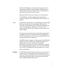
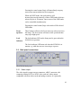
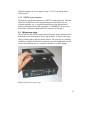
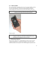
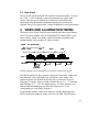
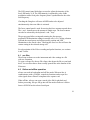
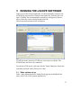
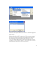
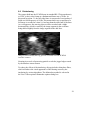
SVM340 Synchronized Video Microscope
User’s Guide
Documentation for the
SVM340 Synchronized Video Microscope
and the uScope control and analysis software v. 1.0
uScope software ©2005 LabSmith.
This manual ©2005 LabSmith. No part of this document may be reproduced
without the written consent of LabSmith.
1 INTRODUCTION ...................................2
1.1
Package contents ............................................................3
1.2
Basic functions ................................................................3
1.3
Computer requirements ..................................................4
1.4
Installing the software .....................................................5
1.4.1
Installing the Hauppauge WinTV video card ...............5
1.4.2
Installing the uScope Software ...................................6
1.5
Setting up the SVM340 ....................................................6
1.6
Field-upgradeable software ............................................7
1.7
Getting help ......................................................................7
2 SVM340 HARDWARE ...........................8
2.1
Front panel controls ........................................................8
2.2
Back panel connections ................................................10
2.2.1
Video output..............................................................10
2.2.2
Digital inputs and outputs..........................................11
2.2.3
External Illuminator ...................................................11
2.2.4
RS232 serial connector.............................................12
2.3
Microscope stage...........................................................12
2.4
Camera module ..............................................................13
2.5
Microscope objective.....................................................13
2.6
Fluorescence filter .........................................................14
2.7
Illuminator module .........................................................14
2.8
Base stand......................................................................16
3 VIDEO AND ILLUMINATION TIMING ..16
4 uSCOPE SOFTWARE.........................17
4.1
4.2
4.3
usc files...........................................................................19
Online and offline operation .........................................19
Upgrading firmware .......................................................20
5 RUNNING THE uSCOPE SOFTWARE 21
5.1
5.2
Video options set-up......................................................21
Color format set-up........................................................23
6 VIDEO RECORDING ...........................24
6.1
Video compression ........................................................25
1
6.2
6.3
6.4
6.5
6.6
Recording speed ............................................................25
Buffering .........................................................................25
Pre- and post trigger recording ....................................27
Starting and stopping recording ..................................28
Deinterlacing ..................................................................29
7 PROBES .............................................31
8 SPECIFICATIONS...............................32
2
1
INTRODUCTION
The SVM340 is an inverted fluorescence microscope with built-in video
camera, fluorescence filter, pulsed Light-Emitting Diode (LED)
illuminator, motorized x-y traverse and focusing actuator. It can directly
image fluorescent or non-fluorescent samples on a standard video monitor
or video recorder.
In addition, the SVM340 includes an advanced programmable
synchronization unit with four inputs and three outputs for synchronizing
image acquisition to external events.
The basic functions can be controlled by the front panel controls or
through the uScope application software included with the instrument.
1.1 Package contents
The SVM340 package should include the following items:
»
»
»
»
»
»
»
»
SVM340 microscope main body
Camera module with one microscope objective according to your order
Hauppauge WinTV PCI video input card and driver disk
Power cable
One RS232 serial cable and one S-video cable
Installation disk with uScope software
This manual
Extra objectives, illumination or camera modules as ordered
If any parts are missing or damaged, please contact your local dealer or
LabSmith immediately.
1.2 Basic functions
The SVM340 combines an inverted fluorescence video microscope with a
programmable synchronizer and software for on-line image acquisition,
processing and storage. You can use the instrument in several ways:
3
»
»
»
As a stand-alone video microscope. Connect the video output from the
SVM340 to an analog video monitor or VCR through the BNC or the
S-video outputs on the rear panel. You can now focus, traverse and
adjust illumination intensity by the controls on the front panel while
observing the image on the monitor.
As a software-controlled video microscope for automatic or manual
acquisition of video sequences, using the on-line image processing and
storage capabilities of the uScope application.
As an integrated part of a complex experiment, synchronizing pulsed
illumination, image acquisition and external devices in response to up
to four trigger input signals.
In each of these modes, you can use microscope objectives with
magnification from 4× to 20×, and acquire and store the video output on
standard analog video storage hardware. With the uScope application, you
can directly store the video data on computer disk as AVI files and
perform advanced real-time video processing.
1.3 Computer requirements
The SVM340 can be used with any computer equipped with a RS232 port
or USB1.0 or greater port and a free PCI slot or USB2.0 or greater port for
the video input card. However, since the uScope software is designed to
stream digitized video sequences directly to disk, it is recommended that
the computer fulfills the following minimum requirements:
»
»
»
»
»
Intel or compatible processor at minimum 2.6 GHz
Windows XP 2003 or newer
One free PCI slot for the video capture card or a free USB2.0 port
1 GB of RAM
80 GB hard disk with 12 ms access time
The SVM340 microscope includes a VGA-resolution analog CCD camera
which outputs a standard RS170 monochrome or NTSC color composite
video signal. The video signal is digitized by a DirectX9.0 compliant PCI
video capture card (LabSmith optionally supplies a Hauppauge PCI video
card) or USB2.0 video capture peripheral (LabSmith optionally supplies an
4
ADS video capture peripheral), capable of digitizing and storing
uncompressed VGA resolution video on disk.
Many PC video input devices include on-board image compression
hardware, converting the video stream into various compressed video
formats. Image compression standards like MPEG are designed for general
visual imagery and may not be suitable for all types of imagery occurring
in microfluidics device diagnostics, e. g. the images of isolated small
particles as recorded in Particle Image Velocimetry (PIV) experiments.
The ability to record uncompressed video is therefore an important feature
of the hardware and software included with the SVM340.
Uncompressed video streams naturally take up more bandwidth and use
more computer processing power for display and storage, so a powerful
computer is recommended. When used on a newer standard PC with
moderately fast CPU and disk speed, uncompressed video sequences can
usually be stored on disk in real time. If used on slower computers, frames
may be lost during recording. Slower computers may also exhibit a
perceptible delay between an imaged event and its appearance on the
computer display.
Also, a large hard disk is recommended for storage of video data. A color
video signal will typically generate 1.6 GB per minute and thus quickly
consume hard disk space.
1.4 Installing the software
1.4.1 Installing the Hauppauge WinTV video card
1.
2.
3.
4.
Turn off the computer and install the card into a free PCI slot
Start up the computer
Insert the WinTV disk into your CD drive
When "Found New Hardware Wizard" pops up check "Install the
software automatically (Recommended)" (this may vary with
Windows version). You can also force Windows to look on the
CDROM for the drivers.
5
5.
6.
7.
8.
A screen should pop up that says
"The software you are installing for this hardware
Hauppauge Win/TV 878/9 VFW Window Driver
has not passed Windows Logo testing..."
Click "Continue Anyway"
When you get the success report, click "Finish"
Next, the same thing may/should happen for the audio driver. You
do not need to install the audio driver for the uScope application.
Now run setup.exe from the WinTV CD. If it tells you that you
need to install DirectX9.0, do so. DirectX9.0 can be downloaded
from the Microsoft web site. Install WinTV following the
instructions on the screen.
1.4.2 Installing the ADS USB2.0 capture peripheral
1.
Insert the CDROM supplied with the ADS peripheral and follow
the on-screen instructions.
1.4.3 Installing the uScope Software
1.
To install uScope, run setup.exe and follow the on-screen directions.
This setup program will link links to uScope on your desktop and
Start menu and copy two files if they are missing from your
Windows/System32 folder: MFC42.dll and MSVCRT.dll. Note: if
your computer does not already have DirectX9.0 or greater
installed you will need to install it before running uScope.
DirectX9.0 is available on the installation CD supplied by
LabSmith or directly from Microsoft’s website. Most computers
will already have this software installed.
1.5 Setting up the SVM340
1. Plug the power cable from the back of the SVM340 into a 90 – 240
VAC power outlet.
2. Connect the 9-pin D-sub serial connector on the back of the SVM340
to a free serial port on the PC. You may use a USB/RS232 converter
device if your computer does not have a RS232 port. LabSmith will
optionally provide a converter upon request.
6
3. Press the power button on the front of the SVM340
4. From your computer, launch uScope.exe
5. A dialog box will pop up that says "Communications properties".
Select the correct COM port and click OK. This dialog will keep
popping up until you succeed in communicating with the SVM or you
click Cancel (then you work offline and uScope does not try to send
commands to the SVM).
Communications settings dialog box.
1.6 Field-upgradeable software
The firmware in the SVM340 is field upgradeable, allowing access to the
latest features as they become available. The firmware is upgraded through
the application software uScope. See the detailed instructions and
precautions for upgrading the firmware in the Software section of this
manual.
1.7 Getting help
This guide is your main source for information on operating the SVM340
and the uScope software. The guide is also available on the uScope CD in
PDF format for viewing with Adobe Acrobat.
Check the LabSmith web site (www.labsmith.com) for user manual
updates, helpful application notes and other technical information to help
you use the SVM340.
7
If you are unable to find the help you need, call the LabSmith technical
support at (925) 292 5161 or send an e-mail to [email protected].
If you need support, please write down the serial number of your SVM340
(located on the bottom of the unit) and the version of the software you are
using. To get the software version number, click Help>About uScope in
the uScope main window.
2
SVM340 HARDWARE
Most of the access to the SVM340 features will go through the uScope
application software. You can, however, access some important functions
directly from the front panel.
Storage buttons/
LED selectors
Lock indicator
LED
Site/light
Toggle buttons
Keypad
Focus
control
SVM340 front panel
2.1 Front panel controls
The Power button and Power LED are located in the upper left corner of
the front panel. When the power is turned on, the LED will flash green and
red while the system runs its initial tests, and turn green when the tests
have passed.
Site-Light
These buttons toggle between SITE mode and LIGHT mode.
8
When the SITE button is lit, the four storage buttons A–D
represent four different stored positions, and the keypad
controls the traverse movements. The focus buttons moves
the objective up and down for focusing.
When the LIGHT button is lit, buttons A–D represent the
four LED banks, and the keypad up and down buttons
control the intensity of the LED banks selected by the A–D
buttons.
A–D
In SITE mode, the buttons A–D represent four stored settings
of the traverse and focus positions and LED intensities.
To recall a stored position, select SITE mode and press and
release a storage button. The traverse will move to the
location and set the four LED intensities to the values of the
stored settings.
To store a traverse position, press one of the storage buttons
and hold it down a few seconds until the button light goes
off. This will store the current traverse position and the LED
settings in the selected storage cell.
In LIGHT mode, the buttons A–D represent four LED banks,
labeled A-D. The 24 LEDs in the illuminator module are
divided into four banks, which can be controlled
individually, see section 2.6. When a LED bank is selected,
the corresponding button lights up. One or more LED banks
can be selected simultaneously by pressing the one or more
of the A–D buttons.
Keypad
In SITE mode, the four buttons will move the traverse in the
x and y directions. Pressing a button will start the traverse
motor at low speed, and after about two seconds motor speed
slowly ramp up to high speed. Pressing the button briefly
allows single stepping of the traverse.
9
Pressing the center button (Stop) will immediately stop any
traverse movement which may be in progress.
When in LIGHT mode, the up/down keys will
increase/decrease the intensity of those LED banks which are
selected by the A–D buttons. One or more of the LED banks
can be controlled simultaneously.
Pressing the center button (Stop) with switch off all selected
LED banks.
Focus
up/down
These buttons will move the focus motor up or down to focus
the image. The focus motor will start at slow speed and then
ramp up to high speed.
Lock
indicator
The lock indicator LED on the front panel is green when the
SVM340 is in position.
The Lock indicator LED turns red when the SVM340 is in
motion, e.g. while the traverse is moving to a preset.
2.2 Back panel connections
The SVM340 back panel
2.2.1 Video output
The video signal is output on two connectors: a BNC connector with
composite, analog RS170 or NTSC video, and an S-video output
compatible with most video cards and analog recorders. It is generally
10
recommended to use the S-video for best image quality, but some monitors
without S-video input may require the composite video signal. The
supplied Hauppauge WinTV card has both S-video and composite input
connectors.
2.2.2 Digital inputs and outputs
The four digital inputs and three outputs on BNC connectors provide TTL
level communication with external equipment. The inputs can be used to
control or strobe the four LED illuminator channels or trigger more
advanced behaviors. The outputs are selectable and include video timing
information, motion status information, and several advanced
programmable flags. The inputs could be connected to digital experiment
controllers like the LabSmith LC880, interlock switches, sensors, or other
external devices, and the outputs connected to other apparatus to facilitate
real-time control and automation.
2.2.3 External Illuminator
This male nine-pin D-sub connector provides 5 V DC power and pulse
signals to drive 4 external illumination sources with settings similar to the
four-bank led module.
Pin connections
1 5 V DC (max 3 A)
2 Chassis Ground (0 V)
3 Chassis Ground
4 Chassis Ground
5 Chassis Ground
6 LED A drive (TTL)
7 LED B drive (TTL)
8 LED C drive (TTL)
9 LED D drive (TTL)
The light intensity of the LED’s of the SVM340 is controlled by pulse
width modulation with a frequency synchronized to the video signal. Full
light intensity means an illumination duty cycle close to 100%.
11
LED drive outputs A–D are negative logic, ie. TTL level is high when
LEDs are off.
2.2.4 RS232 serial connector
The female 9-pin D-sub connector is for RS232 communications. This link
allows the SVM340 to receive programming and commands from an
external controller, e.g., a computer running the uScope application or
LabView through the provided serial cable. A USB/RS232 converter can
be used for computers without an RS232 connector (COM port).
2.3 Microscope stage
The SVM340 is fitted with a replaceable microscope stage, attached to the
main body of the instrument by four magnetic locks. To remove the stage,
simply pull the stage gently up until it releases. The stage top is a polished
stainless steel plate, which can be machined to provide application-specific
mounts for the fluidic device, electrodes, fluid hoses or other fittings.
Removing the microscope stage
12
2.4 Camera module
The camera module is attached to the traverse by magnetic holders and can
be removed by tilting the SVM340 on its side and gently pulling the
camera module down from below the SVM340 body until it comes free.
Important! Before removing or inserting a camera, turn off the SVM340
using the power button at the left of the front panel.
Camera module
Note:
When removing or inserting the camera module, take care not
to apply excessive force since this may damage the traverse
mechanism and compromise traverse accuracy.
2.5 Microscope objective
The microscope objective is a standard DIN type objective with 160 mm
conjugate image distance. To replace the objective, remove the camera
module and unscrew the objective. The SVM340 supports objectives with
13
magnifications from 4× to 20×. Objectives with higher magnification
generally have insufficient stand-off distance to clear the illuminator
LED’s and can only be used with an external illuminator module or other
external light source.
Objective and seat for fluorescence filter
2.6 Fluorescence filter
The fluorescence filter is located in the objective mounting ring right
behind the microscope objective and can be replaced by unscrewing the
objective. The filter size is half inch (12.7 mm) diameter, and the filter fits
into a recess in the microscope mounting ring.
2.7 Illuminator module
The illuminator module consists of four independent banks of LEDs:
? Two banks of each 8 diodes (A and B)
? Two banks of each 4 diodes (C and D)
The following standard illuminator modules are standard:
LED-B: 3 blue (A, B, and D) and one white channel (C)
LED-G: 3 green and one white channel
LED-R: 3 red and one white channel
14
LED-W: 4 white channels
LED-RGBW: 1 red, 1 green, 1 blue, and one white channel.
The illuminator module can be removed from the traverse from the top by
pulling the module upwards.
Removing the illumination module
Note:
When reinserting the illuminator module take care that the
connector pins are all correctly inserted in the receptacle
without bending or damaging the pins. Also take care not to
apply excessive force. Support the camera module from below
with your hand when inserting the illumination module and
press from below to ensure the traverse mechanism is
magnetically seated.
15
2.8 Base stand
The SVM 340 is delivered with four rubber feet attached with 8-32 screws
on a 7.00” × 9.00” rectangle to place the instrument on a plane table
surface. The feet can be replaced by leveling feet which allow fine
adjustment of the instrument or standard optical posts which can be
clamped firmly to an optical table. Contact LabSmith for more information.
3
VIDEO AND ILLUMINATION TIMING
The master clock for the SVM340 is provided by the video signal timing.
The CCD camera outputs video in standard RS170 format (NTSC in the
color version), which is an analog, interlaced format compatible with
standard analog video monitors or video recorders.
Frame
Fields
33 ms full frame
Even
Odd
Even
Odd
Video
LED drive
LED on
(variable)
Timing sequence of the illumination in relation to the video signal
The RS170 interlaced video signal is composed of two fields, called even
and odd fields, each containing every second line of the image. The
interlaced format was defined in the early days of television to avoid
flickering TV images. The even field contains lines 0, 2, 4, … 524 and the
odd field lines 1, 2, … 525. The field frequency is 60 Hz, with one even
and one odd field adding up to a full video frame each 33.3 ms,
corresponding to 30 Hz frame frequency.
To ensure that all lines of the video signal are equally illuminated, the
LED’s flash twice during an image, once in every field. The LED pulse
16
starts in the frame blanking period, and its width can be varied from 0 to
near 100% of a field period, 16.6 ms.
Due to the interlaced readout of the camera sensor, images of fast moving
objects, which move a noticeable distance during the 16.6 ms between two
consecutive fields, may appear jagged at the horizontal edges. See section
below for a discussion of the implications and tools to control the
interlacing effect.
4
uSCOPE SOFTWARE
The uScope software lets you set the functions of the SV340 and control
the video acquisition and on-line processing. It also allows you to recall
and process stored video files.
uScope runs on any PC with Microsoft Windows XP operating system.
Note
The uScope application makes extensive use of the DirectX
software, which is provided by Microsoft Corp. and installed
independently of uScope. If you have installed a local language
version of Windows XP, DirectX will install in the same
language. Consequently, some of the dialog boxes shown
below may appear in the language of your windows
installation.
The uScope main window is divided into the following sections:
?
?
?
?
?
?
The video display window
The LED control panel
The focus control panel
The presets panel
The video recording panel
Probe controls
17
Probe
controls
Presets panel
LED control
panel
Focus
control
Traverse
control
Video
display
window
Video
recording
panel
uScope main window
The video display window shows the off-line or on-line (live) video as
selected in the Video menu. The position indicators to the right and below
the video display indicate the position of the x-y traverse and can be used
to move the traverse. The traverse can also be activated by the keyboard up
and down arrow keys.
18
The LED control panel slider bars are used to adjust the intensity of the
four LED banks, A–D. The LED intensity is adjusted by pulse width
modulation with a fixed pulse frequency that is synchronized to the video
field frequency.
Checking the Gang box will cause all LED banks to be adjusted
simultaneously when one slider is activated.
The focus control panel is used for moving the focus actuator up and down.
The + and - buttons move the actuator in single steps. The focus actuator
can also be activated by the keyboard + and - keys.
The presets panel allow saving and restoring the four traverse
position/LED illumination settings in storage cells A–D. Clicking a button
will load the stored preset and adjust traverse position and LED
illumination to the stored values. Checking the Save box first will store the
current setting in the selected storage cell.
For a description of the Video recording and probe functions, see sections
6 and 7 below.
4.1 usc files
The uScope software saves the instrument and video settings in a file
with .usc extension.
To open a uScope file, choose File>Open, then locate the file on your hard
drive. You can also choose from recently opened files at the bottom of the
File menu.
4.2 Online and offline operation
uScope can work in both online and off-line mode. When on-line, it
communicates with a SVM340, controls its functions and accepts live
video signals from a DirectX compliant video capture card.
When off-line, uScope can open a stored video file for playback and
further processing. uScope will go into off-line mode whenever it fails to
locate a SVM340 on the selected serial port.
19
4.3 Upgrading firmware
The firmware is the software stored inside the SVM340 in non-volatile
memory and controls the internal functions of the instrument, such as
traverse movements, front panel lamps and buttons, and back-panels inputs
and outputs. The firmware is included in the uScope application package
and can be loaded into the SVM340 from within the uScope software.
To upgrade firmware to the latest version:
1. Download the newest version of uScope from www.labsmith.com and
install on your computer following the installation procedure described
in the introduction.
2. Connect and turn on the SVM340 and start up the uScope application
on the PC.
3. In online mode, choose SVM>Update Firmware>Update All
4. Click OK when the update dialog box appears
5. Wait while the firmware is updated. You can follow the progress in the
status bar at the bottom of the uScope main window.
6. When the progress indicator reaches 100%, the upgrade is completed.
Important: Do not turn off or disconnect the SVM340 or the PC while the
upgrade is in progress. This may result in loss of
communication with the instrument that requires LabSmith
assistance to resolve.
20
5
RUNNING THE uSCOPE SOFTWARE
When you run the uScope application, it will automatically connect to the
SVM340 if it is present on a serial port and turned on. If uScope does not
find a SVM340, the communications settings box will appear as shown
above. Select the correct serial port and press OK.
The uScope main window below will appear.
For off-line mode, open the AVI file you want to process off-line. The
SVM340 does not have to be connected.
For on-line (LIVE) mode, click cancel in the "Open" dialog box for on-line
operation, and click Video>Process live video.
5.1 Video options set-up
If the "video capture hardware" dialog doesn't pop up (it should the first
time) click View>Video options>Input device.
21
Video options menu
Click on the video capture card that you want to use. Select the appropriate
capture source.
Make sure that either the BNC composite or S-Video connector output of
the SVM340 is connected to an input of the Hauppauge card, and select
the relevant input connector through the Input connector box. Click
View>Video options>Input connector and select the input that you want
(e.g. Input: 0: Video SVideo In, Output: 0: Video Decoder Out). Click OK.
At this point you should see live video on your screen.
22
Input connector selection box.
You do not have to worry about the audio options since they are not
currently used for the uScope application.
To set the video frame size you can click Video>Video options>Video
frame format. Select 320×240 for low-resolution images and 640×480 for
full-resolution images. Do not change the color space (whatever comes up,
normally RGB24, is correct).
Note:
The DirectX video controls dialog boxes are of general nature
and allow settings incompatible with the SVM340. Do not
change the Video Standard (NTSC_M) or the output aspect
ratio (the size must be 640×480, 320×240, 160×120 or 80×60)
5.2 Color format set-up
The SVM340 can be fitted with either a grayscale (B&W) or color camera,
and the video output should be displayed and stored in corresponding
monochrome or color formats. This is done by means of Look Up Tables
23
(LUT’s), which convert the analog voltage outputs of the video signal to
the appropriate gray scale or color values.
If you have a B&W camera, you want to make sure you are using an 8-bit
LUT, converting the analog voltage into 256 different gray scale levels.
Normally you would use a grayscale LUT, mapping the 256 gray scale
levels into 256 different shades of gray, but you can apply color LUT’s for
false color display. The reason for using false color display is that it is
difficult to distinguish 256 different gray levels on a standard computer
monitor. Converting shades of gray into colors can significantly enhance
visibility of small differences in gray scale value.
You can experiment with false color display by: Click Video>Color
format>Spectrum LUT, etc.
If you have a color camera and you want to keep the color, click
Video>Color format>24-bit RGB. You may also select a monochrome 8
bit with a color camera to save RAM and disk space. Color video data
takes up 8 bits each for the red, blue and green colors, and thus consumes
three times as much disk space and processing time as 8 bit-per-pixel
video.
6
VIDEO RECORDING
One of the main features of the uScope application is the ability to record
long, unbroken video sequences without compression. These video
sequences are stored in standard AVI format, so that they can later be
viewed by Windows Media Player or other video playback software, offline processed by uScope or other video processing software, compatible
with the AVI standard.
To enable uncompressed video recording, uScope makes use of a double
buffering system, described below. The buffering scheme also enables pretrigger recording, enabling you to store a video of what happened before
the trigger instant.
24
6.1 Video compression
Video compression algorithms like MPEG are great for normal TV
recording, but may not work properly when used for scientific video
sequences, which often obey completely different statistics. MPEG video
compression is particularly bad for video sequences containing small,
rapidly moving objects, which is exactly the kind of imagery likely in
microfluidics experiments. Therefore, uScope works entirely with
uncompressed video sequences, making no assumptions about the nature
of the imagery.
6.2 Recording speed
A standard monochrome RS-170 video signal converts into a digital data
rate of 8.9 MBytes/s, which can easily be read into PC RAM memory in
real time. It is also within the capability of modern, fast computers to write
to hard disk in real time at this data rate, provided the computer is not
overloaded by simultaneously executing other disk or CPU intensive tasks.
Color NTSC video signals convert into a data rate of 26.4 MBytes/s, which
can readily be written to RAM memory in real time, but may be too high
to write to hard disk in real time. In that case, some frames scattered
throughout the video sequence are lost, resulting in a stored video
sequence with time intervals of 33.3 ms between most images, but with
66.6 ms, 99.9 ms or some other multiple of the base frame interval
between some individual images.
Such lost frames are called dropped frames. Video sequences with dropped
frames are not suitable for accurate time history analysis, since it is
difficult to know afterwards exactly where frames are missing.
6.3 Buffering
To avoid the problem of dropped frames and to enable pre-trigger
recording, uScope stores digitized video date in cyclic a RAM buffer
simultaneous with the display. This is illustrated in the figure below.
25
Camera
A/D
converter
Video display
Hard disk
RAM buffer
Buffering scheme in uScope
The analog video signal from the SVM340 camera is digitized in the
Hauppauge WinTV card into an 8 bit data stream. This stream is
continually stored in a cyclic RAM buffer in PC memory, such that the
most recent video data is always residing in RAM. As soon as a trigger or
keyboard action stops the recording, you freeze the video sequence in the
RAM buffer, which contains the video of the events prior to the trigger.
This sequence can subsequently be stored on disk.
The duration of the video sequence depends on the amount RAM, set aside
for the buffer. The more RAM installed in the computer, the more buffer
space can be set aside without slowing down other tasks. The initial buffer
size is set to half the available RAM, but you may want to adjust the buffer
size get longer pre-trigger video sequence duration. Buffer size is specified
in The View>Video options>Buffer settings menu.
26
Setting of RAM and disk buffer size
The disk buffer is a contiguous area on the system disk set aside for storing
the video sequence in AVI format. The buffer settings dialogue box allows
you to specify the name and size of the disk buffer. Once the disk buffer
runs full during a recording session, the file system will start to allocate
extra disk space to hold the new data as is comes in. This will considerably
slow down the effective disk writing speed, resulting in dropped frames.
The larger the disk buffer, the longer the video sequence without dropped
frames.
6.4 Pre- and post trigger recording
The figure below illustrates the effect of the buffer size on the pre- and
post trigger recording durations.
27
Trigger
Stored video
Time
RAM Buffer
Stored video
Time
Disk Buffer
Pre-trigger (top) and post-trigger (bottom) recording
For pre-trigger recording, you save the video sequence occurring before
the trigger, stored in the RAM buffer. With post-trigger recording you save
the video sequence occurring immediately after the trigger and temporarily
stored in the disk buffer. The disk buffer is normally larger than the RAM
buffer.
6.5 Starting and stopping recording
The video recording panel at the bottom of the screen allows you to control
the recording duration and trigger mode.
The video recording panel
To record a post-trigger movie, click record at the bottom left. Click stop
to stop recording. The duration of the movie is selected by the slider bar,
the full duration determined by the disk buffer size.
Clicking the Unlimited radio button allows you to record beyond the disk
buffer duration, but at the risk of dropped frames.
To record a pre-trigger movie, click the Save buffer now button. This will
save the image sequence in the RAM buffer
28
6.6 Deinterlacing
The camera built into the SVM340 runs in standard RS-170 (monochrome)
or NTSC (color) video format at a fundamental frame rate of 30 Hz. As
discussed in section 5.1, the full video frame is composed of two interlaced
fields at a field frequency of 60 Hz. This means that every second line of a
full image is recorded at a time 16.6 ms later than the other half of the lines.
As a consequence, fast-moving objects will be recorded with a slight
horizontal blur, which is caused by the image segment in the even lines
being shifted slightly from the image segment in the odd lines.
Image of a horizontally moving particle recorded with the SVM340
interlace camera
Zooming in on such a fast-moving particle reveals the jagged edges caused
by the interlace camera format.
To reduce the effects of the interlacing, uScope includes deinterlace filters,
which will reduce the visual appearance of the blurring caused by the
interlacing by various algorithms. The delinterlace method is selected in
the View>Video options>Deinterlace options dialog box.
29
Selecting deinterlace filter
The best deinterlace filter depends on the nature of the video image and
should be chosen by experimentation. A brief description of the four
algorithms is given here. For more information, see the home page of the
developers, listed in the dialog box.
Weave
This method uses three fields in the calculation and works well on slow
moving material but tends to fail on fast moving material.
Bob
The basic bob algorithm uses the most recent field and fills in the lines
between by interpolation. This method detects weaving artifacts in the
current image it uses bob to get rid of them. This method has a tendency to
bob rather too much and gives poor results on fine static images.
2-frame
This method uses the current frame and the last two to determine whether
to bob or weave a given pixel. This gives better results on both stationary
and moving images than the above two methods but uses more CPU.
30
Although the deinterlace filters improve the visual appearance of the video,
they are designed for general video scenery and may not be effective for
scientific imagery. All filters are based on some form of interpolation
between frames under the assumption that scene motion is continuous
between frames. When the movies are analyzed by various algorithms, the
effect of the deinterlace filter on the result will be algorithm-dependent.
7
PROBES
uScope has sophisticated real-time probe capabilities that allow users to
monitor image properties like color, intensity, variation and video
properties like inferred motion (e.g., particle image velocimetry) in real
time. These real-time measurements can be recorded to disk and can
trigger real-time actions. Please go to:
http://www.labsmith.com/svm340.htm
for an updated users manual with a complete description of how to use and
prescribe probes.
31
8
SPECIFICATIONS
Traverse
Range
Resolution
x: 50mm, y: 75 mm, focus: 8mm
x and y: 10 µm, focus (z): 1 µm
Sample stage
Dimensions
Opening
X × Y: 140mm × 200mm
55 × 80 mm
Camera module
RS-170-BW
RS-170-C
Objectives
Illuminator
modules
Inputs
Outputs
Communication
interface
Analog, interlaced monochrome camera with 1/3”
CCD 640 × 480 pixels, 30 frames/s
Bayer-pattern analog color camera with 1/3” CCD 640
× 480 pixels, 30 frames/s
10× plan 0.25/170
4×
20×
LED-B: 3 blue (center 460 nm, bandwidth 50 nm), one
white bank
LED-G: 3 green (center 560 nm, bandwidth 50 nm),
one white bank
LED-R: 3 red (center 660 nm, bandwidth 50 nm), one
white
LED-W: 4 white banks
LED-RGBW: 1 red, 1 green, 1 blue, 1 white bank.
4 programmable digital inputs, TTL level
Composite analog video out
S-video out
3 programmable digital outputs TTL level
4 external illuminator trigger/drivers, TTL level
Serial RS232, 9 pin D-sub connector.
32
Physical
Dimensions
Weight
Power
requirement
W × L × H: 208 × 267 × 85 mm
2.8 kg
90–240 VAC 47–63 Hz, 100 VA
33