1
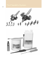
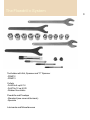
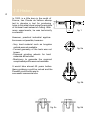
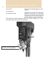
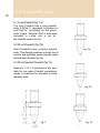
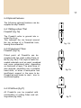
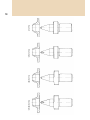
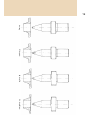
User guide
All rights reserved. No part of this publication may be
reproduced or transmitted in any form or by any means,
electronic or mechanical, including photocopy, recording
or any information storage and retrieval system, without
permission in writing from the publisher.
This handbook has been carefully prepared and translated.
Flowdrill does not accept any responsibility for errors in
the handbook and any consequences resultant therefrom. No
guarantee can be given that the details are free from patent
rights assigned to third parties. All data and comparative
details should be understood as being indicative
without obligation. Because Flowdrill friction drilling
procedures are continuously being further developed, the
details given may not provide any indication of the current
state of development, availability or possibilities of
delivery. The producer's current lists should be consulted for
information.
Copyright by FLOWDRILL B.V. HOLLAND
Edition 2003
FLOWDRILL B.V.
INDUSTRIETERREIN "LAGE WEIDE"
SAVANNAHWEG 70
NL 3542 AW UTRECHT
TEL: 31-30-2416606
FAX: 31-30-2413860
Email address: [email protected]
URL: http://www.Flowdrill.nl
We care about the (w)hole
Flowdrill ® is the registered trade mark of Flowdrill b.v. Holland
Table of Contents
1
Equipment for the Flowdrill® system
1.0 History
2.0 Introduction
3.0 Flowdrill - Ideal for automation
4.0 How the Flowdrill works
5.0 Flowdrill parameters
6.0 Flowdrill types
7.0 Applications of Flowdrills
8.0 Suitable materials
9.0 Working life - Influential factors
10.0 Work-piece material and lubrication
11.0 Tapping information
12.0 Flowdrill process with CNC
13.0 Starter Set
14.0 Parameters for metric thread tools
15.0 Tables of torque and pull strength
16.0 Maximum material thickness for thread holes
17.0 Hints & Tips
18.0 Thread tables
The Flowdrill ® System
2
The Flowdrill ® System
3
Toolholder with Nut, Spanner and "C" Spanner
-FDMC2
-FDMC3
Collets
-Fd 430e 6 up till 14
-Fd 470e 12 up till 20
-Rubber flex collets
Flowdrills and Flowtaps
-Standard (see cover at the back)
-Specials
Lubricants and Miscellaneous
1.0 History
0,5h
3à4xh
In 1923, in a little barn in the south of
France, Jan Claude de Valliere attempted to develop a tool for producing
holes in thin steel sheet using the principle
of frictional heat instead of cutting. After
many experiments, he was technically
successful.
h
4
D1
fig. 1
However, practical industrial applications were not possible, because:
- Very hard material such as tungsten
carbide was not available.
- Correct geometry of the tools was not
known.
- Diamond grinding wheels for hard
materials did not exist.
- Machinery to generate the required
complicated profile were not available.
fig. 2a
It would take almost 60 years before
these problems could be solved and the
Flowdrill could find its way to
successful commercial use.
fig. 2b
fig. 2c
fig. 2d
2.0 Introduction
5
A Flowdrill(fig.3) is a lobed, conical
tungsten carbide tool. When rotated at
high speed and pressed with high axial
force into sheet metal or thin walled
tube, generated heat softens the metal
and allows the drill to feed forward,
produce a hole and simultaneously
form a bushing from the displaced
material (fig. 1).
There are numerous possible applications for Flowdrill; it increases effective
wall thickness for threaded connections
or soldered joints etc. (fig. 2a-f).
Shank
Collar
Cylindrical
part
Conical
part
Flowdrill
point
2a Chipless drilled hole for spraying
appliances. No chips, no broken
drills.
2b Gas tight connection
2c Threaded connection
around the hole
with
rim
fig. 3
2d Threaded connection (Flat face)
2e Bearing or shaft support
2f Water tight + soldering high pressure
fig. 2e
fig. 2e
fig. 2f
3.0 Flowdrill® - Ideal for Automation
6
(a) No swarf
lighting and household appliance industries, etc.
(b) Long tool life
Although the process itself has been
applied for some time, it is necessary
for the user to understand the nature of the
Flowdrill process, the various types of
Flowdrills and the physical requirements
of the drilling machine for best
Much experience has been gained in the
automobile, gas-heating, metal furniture,results.
(c) Accurate hole form
Automatic Turret drilling Head suitable
for any column drilling machine
4.0 How the Flowdrill® works
7
The standard Flowdrill design is shownof the drill feed.
in figure 3. Its working portion consists As the material softens, axial force is
of a pointed end, a cone and a parallelreduced and feed rate increased (fig. 4
body. Both the cone and the body ared,e,f,g,h).
polygon shaped. This specially
designed shape plays an essential part
Final size and shape of the Flowdrilled
in the Flowdrill process. The Flowdrill hole and bushing are determined by the
also has a collar and a straight shank.diameter and cone shape of the
Flowdrills are made of a carbide gradeFlowdrill.
developed to satisfy the unique charac-Material that flows back towards the
teristics of the Flowdrill operation.
Flowdrill can be formed into a collar
(fig. 4 i) or cut off flush to the surface
4.1 The phases of Flowdrill
with a 'flat' type Flowdrill (fig. 4 k).
4.1.3 High axial force:
4.1.1 Initial Contact
- Develops heat rapidly in Flowdrill
Relatively high axial pressure ( F. ax), creating thermal stress.
combined with high rotational speed is- Increases feed rate - reduces drilling
needed to generate heat between Flowdrill time.
and workpiece (fig. 4 a,b,c).
- May alter the physical properties of
The Flowdrill temperature rises rapidly to workpiece material.
about 650 - 750 º C. and the w
orkpiece 600 º C
4.1.4 Low axial force:
.
High axial force is needed until the
Flowdrill point penetrates the material. - Provides gradual warming, reducing
stress in Flowdrill.
4.1.2 Material Flow
- Increases drilling time which can result
in excessively high temperatures.
Displaced material initially flows up - Reduces torque on Flowdrill.
towards the Flowdrill; when the point - Requires less power input.
penetrates, material flows in the direction
fig. 4a
fig. 4b
fig. 4c
8
f ig. 4d
f ig. 4e
f ig. 4f
f ig. 4g
f ig. 4h
f ig. 4i
f ig. 4j
f ig. 4k
5.0 Flowdrill® parameters
9
The Flowdrill diameter
determines values for:
Axial forces
F ax (N)
Speed Rpm
5.2 Speed (n)
See fig. 5a
n(min-1)
Power
5b
P(kW)
5c
Material thickness (max.) h(mm)
6
5.1 Axial force ( F. ax)
Keep speed as low as possible to obtain
longer Flowdrill life.
Speed selection is influenced by material thickness as well as material type.
Thicker stainless- and high carbon steel
require lower speed and will usually result
in shorter Flowdrill life.
As a general rule, soft non-ferrous
materials require more speed: the softer
the material, the higher the speed.
Maximum axial force is proportional to
the Flowdrill diameter.
As temperature increases, axial forceGraphics 5a, b, c, are based on Fe.360
required reduces, feed rate increases. h=2mm.
F ax ( N )
7000
6000
5000
4000
3000
2000
1000
1
2
3
4
5
6
7
8
9
fig. 5a
10 11 12 13 14 15 16 17 18 19 20 21 22 23 24 25mm.
Flowdrill
mm.
10
Rpm
7000
6000
5000
4000
3000
2000
1000
1
2
3
4
5
6
7
8
9
Ideale startpositie (zie hoofdstuk 14.0)
fig. 5b
10 11 12 13 14 15 16 17 18 19 20 21 22 23 24 25mm.
Flowdrill mm.
Optimaal Flowdrill bewerkingsgebied
Randgebieden met hogere Flowdrill slijtage
11
12
5.3 The effects of different speed 5.4 Power (kW)
are shown in this example:
Most good quality drilling machines are
Material
thickness (h)
2.0 mm
2.0 mm
Flowdrill dia.
7.3mm
7.3mm
Speed (n)
3 000 min- 1
1750 min-1
Drilling time
1. 5 sec.
Flowdrill
Temperature
700 º C
2.0 sec.
600 º C
suitable for Flowdrill, provided they
meet the power and speed requirements.
The required power of the drilling machine
is shown on chart (fig. 5c).
13
P kW
7
6
5
4
3
2
1
1
2
3
4
5
6
7
8
9
Optimum operation area
mm.
fig. 5c
10 11 12 13 14 15 16 17 18 19 20 21 22 23 24 25mm.
Flowdrill
14
5.5 Material Thickness (h)
Fig. 6 indicates maximum material
thickness that can be Flowdrilled with
Maximum material thickness (h.Max) is standard long or short Flowdrills. See also
proportional to the Flowdrill diameter. table in chapter 16.0
Minimum thickness follows the general Special Flowdrills can be supplied to meet
rule: h Min = approx. 0.2 x D 1 up to unusual needs.
2mm, which rule is suitable for most of For greater thickness an extra long L 5
the bigger sizes. D1 is the Flowdrill may be necessary.
diameter.
(Ask for advise)
Flowdrill life is reduced if used on
heavier gauge material or materials
with high tensile strength.
Notes:
15
When the application is outside the range of max. lines given in this
graphic, please call our technical service for their experience
h in mm.
10
9
8
7
6
5
4
3
2
Flowdrill type short for conical bushing
type long for cylindrical bushing
1
1
2
3
4
5
6
7
8
fig. 6
9 10 11 12 13 14 15 16 17 18 19 20 21 22 23 24 25mm.
Max. short for conical bushing Max. short flat for conical bushing
Max. long for cylindrical bushing Max. long for conical bushing
Max. long flat for conical bushing
Flowdrill
mm.
6.0 Flowdrill® types
16
6.1 Long Flowdrill (fig. 7a)
The long Flowdrill has a long parallel
body (L5)(fig.7) designed to produce a
hole that is cylindrical for the entire
bush length. Material that is backward
extruded is rolled into a rim by
the Flowdrill collar (fig. 8e).
6.2 Short Flowdrill (fig. 7b)
Short Flowdrills have a shorter parallel
body. This design produces a bush that is
conical and provides great strength when
formed into a thread (fig. 8a).
fig. 7a
6.3 Short Special Flowdrill (fig. 7c)
Special L 4 & L 5 dimensions are available for use when Flowdrill penetration
length is restricted for example in small
diameter tube.
fig. 7b
fig. 7
fig. 7c
17
6.4 Optional Features
The following optional features can be
supplied on any Flowdrill:
6.4.1 Milling cutters "Flat
Flowdrill" (fig. 7d)
The Flowdrill collar is ground into a
cutter (fig. 8c,g).
This removes the rim formed around
the top surface of a Flowdrilled hole,
leaving the surface flat.
fig . 7d
6.4.2 Fluted point "Rem
Flowdrill" (fig.7e)
Fluted point: all Flowdrills can be
supplied with two small cutting flutes at
the tip (fig. 8b,f). This style is useful for
coated materials such as paint, anodised
and some galvanised steel, depending
on thickness of layer. The axial force is
also reduced, permitting use in portable
hand drills, or when a work-piece has
insufficient support in the area to be
Flowdrilled and tends to dent , due to
insufficient rigidity.
fig. 7e
6.4.3 Flat Rem (fig.7f)
All Flowdrills can be supplied with
combination of cutting flutes and milling cutters (fig. 8d,h).
fig. 7f
18
8a. short
8b. short rem
8c. short flat
8d. short flat rem
19
8e. long
8f. long rem
8g. long flat
8h. long flat rem
7.0 Applications of Flowdrills
20
7.1 Flowtapping
7.1.2 Example
The most common use of Flowdrills isM6 in 2 mm Fe 360
to provide a high strength threaded fastener in thin sheet metal or tube. AUse Flowdrill: FD - 5.3 short
Flowdrilled hole may be tapped with
conventional cutting taps or preferably,Use Flowtap
FT - M6
with cold form Flowtaps. Flowtapping
resembles Flowdrill except the opera-Thread strength 17 kN.
ting temperature is much lower; instead
of cutting, Flowtaps cold-form the
thread(no swarf). The diameter of the
Flowdrill determines the final thread
form,-depth and -strength. Tables in chapter 18.0 (back cover) show the recommended Flowdrill diameters for various
thread sizes.
7.1.1 Advantages of Flowtaps
compared with thread cutting
taps
- No weakening of the threaded wall
due to metal removal.
- Higher production speed.
- Better thread strength through cold
forming of the material.
- Less chance of pitch errors that can be
incurred when cutting threads.
- No swarf, no pollution or chip removal problems.
- Less tap breakage.
- Good tap life.
21
7.2 OtherApplications
Bearing support ( f ig. 2e)
Soldered connection ( f ig. 2f)
f ig. 2e
fig. 2f
8.0 Suitable materials
22
2
8.1 Steel (up to 700 N/mm
tensile
strength).
8.2 Non-ferrous metals (with the exception of brittle
CuZn40Pb2).
material,
like
8.3 Aluminium with less than 5% Si.
8.4 Stainless steel, acid resistant steel.
In some cases it is desirable to test the
suitability of the Flowdrill system. In
particular in case of zinc coated materials.
9.0 Working Life - Influential factors
23
9.1 Flowdrills are made of specially 9.10 Flowdrill temperature should not
developed carbide. This will maintainexceed dark red colour.
its strength at high temperatures but is
sensitive to thermal stress. Local9.11 Speed and axial force should be
cooling should be avoided.
adjusted optimally under observation of
the temperature of the FD (indicated by
9.2 Flowdrills cannot withstand high dark red colour).
mechanical shock. They should not be
dropped and hard impact onto the9.12 Hole quality will be affected by
surface of the workpiece, as well asbuild up of work-piece metal on the tool,
welded spots should be avoided.
also from film caused by anodised aluminium or zinc from galvanising.
9.3 Avoid radial forces on the Flowdrill
9.13 Timely removal of built up material
9.4 Torsional stability of the Flowdrill with diamond file
is important. Too rapid release of
torsional load caused by fast break through
9.14 Cleaning with a diamond file will
(very high feed rate) can cause fatigue. extend tool life.
9.5 A similar condition can occur due to9.15 Don't dwell at depth when using
wind up if start pressure is too great.
Flowdrills - especially flat Flowdrills dwelling reduces cutter life.
9.6 DO NOT DRILL an unfinished
hole, risking taper lock due to shrink-9.16 Protect the Flowdrill and drilling
age.
machine spindle for overheating by using
the special Flowdrill toolholder with cool9.7 Instability due to wear in machine ing fan.
spindle or collet can allow the Flowdrill
to wander. Stress caused by misalignment can break the Flowdrill.
9.8 Finish -quality- in the Flowdrilled
hole will deteriorate when the Flowdrill
becomes worn.
9.9 Regular lubrication will increase life
of Flowdrill. Use Fdks for lubrication of the
FD every 1-5 holes on the hot rotating FD.
10.0 Work-piece material and lubrication
24
Flowdrill lubrication
Flowdrill results depend on the material's physical properties, such as tensile
strength, hardness, chemical content
and conductivity. Generally all malleable materials can be Flowdrilled.
Lubrication of the Flowdrill can work
against the need to generate heat but is
required in small amounts to prevent
pick-up or adhesion on the carbide
surface, particularly when Flowdrilling
aluminium. Flowdrill lubricants are specially developed to meet this criterion.
10.1 Remark
Lubricate while Flowdrill is still running,
directly after Flowdrill operation.
10.2 Flowdrill lubricants
FDKS paste and FDKS fluid to use for
drilling in steel, stainless steel, copper and
brass. FDUN paste to use for drilling in
aluminium.
10.3 Tapping lubrication
High material deformation during
tapping places strong demands on the
lubricant used. To obtain optimum
speed and quality we recommend use of
Flowdrill FTMZ high pressure lubricant.
It should be applied for each hole tapped.
Dispensers are available for automatic
production.
Avoid overheating the lubricant.
25
11.0 Tapping
mation
11.0
Tapping infor
information
26
11. 1 Tapping Torque
11.3 Recommended Flowdrill dia-
The torque required for tapping (coldmeters for tapping (backcover)
forming) threads depends on theRecommended Flowdrill diameters
Flowdrill diameter, Rpm, work-piece produce 65% thread depth.
material and lubrication.
Because the cold forming process tougCold forming threads generally usehens the material, thread strength is
about 20 % more torque than cutting.greater than when a cutting tap is used
However, the conical hole shape gene(fig. 11a).
rated to give maximum thread strengthLarger Flowdrill diameters have a
in a Flowdrilled bushing can double thefavourable effect on Flowtap life.
torque required (fig. 11b).
They may also be advantageous in
some very tough materials or materials
11.2 Flowtap speed (fig. 11c)
that tend to recover or shrink after
forming (for example M 6 thread can
See also chapter 14.0.
be formed using 5.3 - 5.4 - 5.5 Flowdrill,
depending on conditions)
fig. 11a
Required torque is dependant on the:
- Roughbore diameter
- Rpm
- Pitch
- Lubrication
Influence of roughbore
roughbor
diameter on the torque
torqu
27
Rpm
100
200
400
600
800
1000
kW
Torque Nm
304
Fe 360
Cu
in Fe 360
RPM
Nm
kWatt
Example
M10
200
10
0,2
Threaddiameter
in mm.
12.0 Flowdrill® process with CNC
28
A4
Material: Mild Steel (ST37)
Material thickness: 3 mm
FEED RATE - mm / minute
CNC-PROGRAM
TIME
WORKING PART
(Zeit)
(Weg)
FEED RATE
(Vorschub)
2.73
0 - 2 mm
2 - 4 mm
4 - 7 mm
7 - 11 mm
11 - 14 mm
14 - 18 mm
150 mm/ min
250 mm/ min
350 mm/ min
550 mm/ min
700 mm/ min
1000 mm/ min
1000
950
900
850
800
750
700
650
600
550
500
450
400
350
300
250
200
150
100
50
0
0
1
2
3
4
5
6
7
8
9
10
11
12
13
14
Tool Size
15
16
17
18
19
20
21
22
23
Tool Type
25
Drawing Number
FD 7.3 (L1 = 18mm - L4 = 10mm ) Long / Flat
TOOL WORKING PART - mm
24
A4
000
Size
Job No
00000
00
P.L No
00
00
Detail
Issue
A Flowdrill's feed rate is determined byrate.
pressure - initial pressure is quite high,Feed and rates of acceleration will vary
to create frictional heating. As the workaccording to Flowdrill size, Flowdrill
piece softens, it allows the drill to speed, material type and thickness, but
advance, the rate of advance increases
correct feed can be established fairly
with heating and also as the drill pointeasily by trial and observation. The aim
penetrates through the material.
is to achieve and maintain a constant
The required accelerating feed rate can
dull red glow while the tool is drilling.
be achieved by hand or with pneumatic
feed devices.
Example of feed for 7.3 (M8) long/flat
If CNC is to be used, this effect has toFlowdrill through 3.0mm thick mild
be simulated with a slow initial feed steel. (As a guideline, depending on
rate accelerating to a high final feedmachine and material)
13.0 Starter Set
29
A4
Material: Mild Steel (ST37)
Material thickness: 3 mm
FEED RATE - mm / minute
CNC-PROGRAM
1000
950
900
850
800
750
700
650
600
550
500
450
400
350
300
250
200
150
100
50
0
0
1
TIME
(Zeit)
WORKING PART
(Weg)
FEED RATE
(Vorschub)
3.11
0 - 2 mm
2 - 4 mm
4 - 7 mm
7 - 11 mm
11 - 14 mm
14 - 16. 6 mm
150
250
350
550
700
250
2
3
4
5
6
1.4 mm space (adjustable) for rim or boss
forming (Page 16 section 6.1)
mm/ min
mm/ min
mm/ min
mm/ min
mm/ min
mm/ min
7
8
14
9
10
11
12
13
14
15
16
17
18
19
20
21
22
23
24
25
TOOL WORKING PART - mm
Tool Size
Tool Type
FD 7.3 (L1 = 18mm - L4 = 10mm )
Long/Standard
A4
Size
Example M8, Fe 360 3mm:
Drawing Number
000
Job No
00000
00
P.L No
00
00
Detail
Issue
13.9 Reduction cone 3-2 (optional extra)
13.1 Flowdrill 7.3 long (average life 13.10 Diamond file (optional extra)
approx. 10,000 holes)
13.11 Ejecting drift key (optional extra)
13.2 Flowdrill lubricant Fd ks paste
13.3 Toolholder FD MC2 (locking
spanners included)
13.4 Collet Fd 430E-8
13.5 Flowtap M8 (average life approx.
10,000 holes)
13.6 Flowtap lubricant Ft mz
13.7 FD-Case (keeps kit together)
13.8 Tapping
extra)
attachment
(optional
30
14.0 Parameters for metric thread tools
M 12
M 10
M8
M6
M5
M4
M3
M 2
14.8
10.9
9.2
7.3
5.3
4.5
3.7
2.7
1.8
Flowdrill
Diameter
mm
1200
1400
1800
2000
2200
2400
2500
2600
3000
3200
Flowdrill
Rpm
2.7
2.2
1.7
1.5
1.3
1.0
0.8
0.7
0.6
0.5
Motor capacity
kW.
5
4
3
3
2
2
2
2
2
2
Production time
sec.
200
250
330
400
500
650
800
1000
1350
1600
Flowtap
Rpm
Mild steel FE 360 2mm. Indication to start with
M 16
18.7
Thread size
M 20
15.0 Tables of torque and pull strength
31
9s
6s
Thread M4
10 s
13 s
15 s
M5
16 s
17 s
24 s
M6
27 s
37 l
45 l
s=Short Flowdrill
l=Long Flowdrill
M8
Pull out strength in [kN] 1kN=100Kg.
Material: Fe 360 Thickness: 1.0 - 5.0 mm
Material
Thickness
h=mm
1.0
1.5
2.0
3.0
4.0
5.0
Thread
Size
5
M4
M5
9
8
11
13
17
20
27
M6
Torque in [Nm]
Material: Fe 360 Thickness: 1.0 - 5.0 mm
Material
Thickness
h=mm
1.0
1.5
2.0
3.0
4.0
5.0
28
50
67
M8
52 l
68 l
M10
66
98
M10
67 l
86 l
106 l
M12
136
163
269
M12
97 s
115 l
141 l
M16
197
M16
142 s
162 s
>200 s
M20
32
16.0 Maximum material thickness
for thread holes
Thread
Max. material thickness
Total length
working part
Flowdrill
diameter
for
Flowtapping
Short
Short/Flat
Long
Long/Flat
Shaft
Ø
Short
Long
M2
M2.5
M3
M4
M4 x 0.5
1.8
2.3
2.7
3.7
3.8
1.6
1.6
1.7
1.8
1.8
1.8
1.9
2.0
2.2
2.2
2.2
2.3
2.4
2.6
2.6
3.2
3.5
3.7
4.2
4.2
6
6
6
6
6
5.8
6.1
6.7
8.1
8.2
7.8
8.1
8.7
10.3
10.5
M5
M5 x 0.5
M6
M6 x 0.75
M6 x 0.5
4.5
4.8
5.3
5.6
5.8
1.9
1.9
2.0
2.0
2.0
2.4
2.4
2.5
2.5
2.6
2.7
2.7
2.9
2.9
3.0
4.6
4.7
5.0
5.0
5.2
6
6
6
6
6
9.2
9.6
10.3
10.8
11.2
11.8
12.4
13.5
14.2
14.7
M8
M8x 1
M8 x 0.75
M10
M10 x 1.25
7.3
7.5
7.6
9.2
9.3
2.2
2.3
2.3
2.6
2.6
2.9
2.9
2.9
3.2
3.3
3.3
3.4
3.4
3.7
3.7
5.9
6.0
6.0
6.6
6.7
8
8
8
10
10
13.5
14.0
14.1
16.8
17.0
18.1
18.7
18.8
22.5
22.8
M10 x 1
M12
M12 x 1.5
M12 x 1
M14
9.5
10.9
11.2
11.5
13.0
2.6
2.8
2.8
2.9
3.0
3.3
3.5
3.6
3.6
3.9
3.8
4.0
4.1
4.2
4.5
6.7
7.2
7.3
7.3
7.9
10
12
12
12
14
17.3
19.8
20.3
20.8
23.5
23.2
26.4
27.1
27.8
31.3
M14 x 1.5
M16
M16 x 1.5
M18
M18 x 1
13.2
14.8
15.2
16.7
17.5
3.1
3.3
3.4
3.5
3.7
4.0
4.2
4.3
4.6
4.8
4.6
4.8
4.9
5.2
5.6
8.0
8.5
8.7
9.2
9.5
14
16
16
18
18
23.8
26.9
27.6
30.4
31.9
31.6
35.4
36.3
39.7
41.5
M 20
M 20 x 1.5
M 20 x 1
G1/16
G1/8
18.7
19.2
19.5
7.3
9.2
3.8
3.9
3.9
2.3
2.6
5.0
5.1
5.2
2.9
3.2
5.7
5.8
5.8
3.3
3.7
9.9
10.0
10.0
5.9
6.6
18
18
18
8
10
34.1
35.1
35.6
13.5
16.8
44.3
45.5
46.2
18.1
22.5
G1/4
G3/8
G1/2
G3/4
12.4
15.9
19.9
25.4
2.9
3.4
4.0
4.8
3.8
4.5
5.2
6.2
4.3
5.0
5.9
7.0
7.8
8.9
10.0
10.4
12
16
18
20
22.4
28.9
36.3
46.4
29.8
37.9
47.0
59.6
Data based on Fe 360
17.0 Hints & Tips
33
17.1
Observation in process
Possible Causes
Flowdrill point wanders Worn Machine Spindle,
(can break Flowdrill)
Bearings
Worn collet
Excessive start pressure
Spindle speed too low
Flowdrill overheating
Colour bright red
Flowdrill sparkles
Spindle speed too high
Feed rate too slow
17.2
Observation on Work-piece
Split collar (daisy petals) Start pressure/feed
too high or spindle
speed too slow or final
feed to slow. Pilot hole
or Rem FD may help
Flash or burr on edge of Drill point wanders
collar
Excessive discoloration Feed too slow or spindle
around hole
speed too high
17.3 Cycle Time
A guide to process speed for 2 mm Fe 360 is:
1 second + 1 second for each millimetre of material
thickness i.e. Flowdrill time is 3 sec. approx.
This guide can be used up to about diam. 12mm. Larger
Flowdrills take longer but cycle time should not exceed 15
seconds.
17.3.1
Operation examples
M8
M6
2400
Rpm
2200
800 N
F. ax
1000 N
0.75 kW
Motor capacity
1 kW
1.5 - 2 sec.
Operation time
2 - 3 sec.
1.0 mm
Material Thickness
2.0 mm
17.4 Flowtaps
Consult the cover of this technical guide for the right diameter.
17.5 Check the table chapter 14.0 for the right speed.
17.6 Lubricate before every action, the Flowtap as well as the bush
18.0 Thread tables
Metric thread
Thread
Pitch/mm
M2
M 2.5
M3
M4
M5
M6
M8
M 10
M 12
M 16
M 20
0.4
0.45
0.5
0.7
0.8
1.0
1.25
1.5
1.75
2.0
2.5
Thread
Pitch/mm
M4
M5
M6
M6
M8
M8
M 10
M 10
M 12
M 12
M 16
M 16
M 20
M 20
0.5
0.5
0.75
0.5
1.0
0.75
1.25
1.0
1.5
1.0
1.5
1.0
1.5
1.0
US thread UNC
Flowdrill diameter
1.8
2.3
2.7
3.7
4.5
5.3(5.4)
7.3(7.4)
9.2
10.9
14.8
18.7
Thread
No. 4
No. 5
No. 6
No. 8
No. 10
No. 12
1/4
5/16
3/8
7/16
1/2
9/16
5/8
3/4
Metric thread fine
G 1/16"
G 1/8"
G 1/4"
G 3/8"
G 1/2"
G 3/4"
G 1"
Thread per inch
28
28
19
19
14
14
11
Flowdrill diameter
2.5
2.9
3.1
3.8
4.3
4.9
5.7
7.2
8.7
10.2
11.7
13.2
14.7
17.8
40
40
32
32
24
24
20
18
16
14
13
12
11
10
US thread UNF
Flowdrill diameter
3.8
4.8
5.6
5.8
7.5
7.6
9.3
9.5
11.2
11.5
15.2
15.5
19.2
19.5
Thread
No. 4
No. 5
No. 6
No. 8
No. 10
No. 12
1/4
5/16
3/8
7/16
1/2
9/16
5/8
3/4
BSP thread
Thread
Thread per inch
Thread per inch
Flowdrill diameter
2.6
2.9
3.2
3.9
4.4
5.0
5.9
7.4
9.0
10.4
12.1
13.6
15.2
18.3
48
44
40
36
32
28
28
24
24
20
20
18
18
16
US thread NPT
Flowdrill diameter
Thread
Thread per inch
Flowdrill diameter
7.3
9.2
12.4
15.9
19.9
25.4
31.9
1/16"
1/8"
1/4"
3/8"
1/2"
3/4"
1"
27
27
18
18
14
14
11.5
7.0
9.4
12.4
15.8
19.6
24.9
31.4
Sizes based on Fe 360 2mm
Thicker material or material with greater tensile strength (stainless) Flowdrill diameter 0.1 mm bigger