1
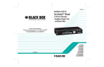
Operating Manual
RMUPS1000, RMUPS1500
RMUPS2500, RMUPS3000
RMUPS4000, RMUPS5000 & RMUPS6000
ServSwitch User's Manual.doc
-1-
Revision 4/04
Introduction
This user manual has been written to provide basic information
about the RMUPS UPS.
It will describe the key features of the UPS, as well as detail
referring to unpacking and installation, operation & configuration
and troubleshooting. It also includes a section on software
installation and general connectivity.
The specification section outlines all of the detailed parameters
of operation of the RMUPS UPS and provides general
information on approvals and certification.
The UPS should be installed according to the instructions in this
manual. Failure to do so could result in safety issues. It could
also invalidate your warranty.
ServSwitch User's Manual.doc
-2-
Revision 4/04
Safety Information
Please retain this user manual in close proximity of the UPS
for future reference.
Since the UPS unit operates from mains power and contains a
number of high current back-up batteries, the information in this
chapter is important to all personnel involved. Please take the
time to read this section before unpacking, installation and
operation of this UPS.
Storage and transportation
Because of the high energy stored within the batteries, the UPS
equipment must be handled with due care and attention. The
UPS must always be kept in the position marked on the external
packaging and must not be dropped.
Installation
Do not operate the equipment in the presence of flammable
gases or fumes. Operation of any electrical equipment in such
an environment constitutes a safety hazard. Do not place the
UPS in an unventilated room or enclosure.
The UPS must be installed in accordance to the instructions
within this manual. Failure to recognise the electrical hazards
could prove fatal.
Do not remove or unplug the input cord when the UPS is turned
on. This removes the safety ground from the UPS and the
equipment connected to the UPS.
Do not open the UPS cabinet. Some components inside the
UPS cabinet carry high voltage. To touch them may prove fatal.
All operations inside the UPS must be carried out by an
authorised service engineer from the manufacturer or agent
authorised by the manufacturer.
ServSwitch User's Manual.doc
-3-
Revision 4/04
Batteries
Once batteries have reached the end of their life, ensure they
are disposed of properly. Refer to your local codes for disposal
requirements.
Never dispose of batteries in a fire. Batteries may explode when
exposed to flame.
Replace batteries with the same number and type of batteries or
battery packs as originally installed in the equipment.
ServSwitch User's Manual.doc
-4-
Revision 4/04
Information de sécurité
Veuillez garder ce manuel d’utilisation près de l’UPS .
L’UPS fonctionnant à partir du réseau et contenant des
batteries à fort courant, les instructions de ce chapitre sont
importantes pour tous les personnels impliqués. Veuillez
prendre le temps de lire cette partie avant de d éballer, installer
et mettre en route cet UPS
Stockage et transport
A cause de l’énergie stockée dans les batteries, l’équipement
doit être manipulé avec précaution. L’UPS doit être à tout
moment maintenu dans la position mentionné sur l’emballage et
ne doit pas chuter.
Installation
Ne pas utiliser l’équipement en présence de gaz ou vapeurs
inflammables. L’utilisation d’équipements électriques dans un tel
environnement est dangereux. Ne pas placer l’UPS dans un
local fermé ou non ventilé.
L’UPS doit être installé suivant les instructions de ce manuel.
Tout manquement à ces instructions peut s’avérer fatal.
Ne pas enlever ou débrancher le cordon d’entrée quand l’UPS
est en marche. Ceci retire la masse de sécurité de l’UPS et de
l’équipement connecté à celui-ci.
Ne pas ouvrir l’habillage de l’UPS. Certains composants de
l’UPS sont à des tensions élevées, les toucher peut être fatal.
Toutes les manipulations à l’intérieur de l’UPS doivent être faites
par les personnels autorisés par le fabricant.
ServSwitch User's Manual.doc
-5-
Revision 4/04
Batteries
Dès que les batteries ont atteint leur fin de vie , s’assurer
qu’elles soient débarrassées proprement. Se référer aux régles
locales en vigueur à ce sujet.
Ne jamais mettre les batteries dans le feu, elles peuvent
exploser en présence d’une flamme.
Remplacer les batteries ou les pack batteries par la même
quantité et le même type que celles installées dans
l’équipement d’origine.
ServSwitch User's Manual.doc
-6-
Revision 4/04
Sicherheitsinformationen
Bitte bewahren Sie diese Bedienungshinweise in der Nähe
der USV auf.
Da die USV mit Netzspannung betrieben wird und HochstromBackup Batterien enthält sind die Informationen in diesem
Kapitel für alle damit in Berührung kommenden Personen von
grösster Wichtigkeit. Bitte nehmen Sie sich die Zeit diese zu
lesen bevor Sie die Anlage auspacken, installieren und in
Betrieb nehmen.
Lagerung und Transport
Durch die hohe Energie die in den Batterien enthalten ist, muss
die USV mit der erforderlichen Sorgfalt behandelt werden. Die
USV muss immer in der auf der Verpackung markierten Position
gelagert und transportiert werden und darf nicht gestaucht oder
geworfen werden.
Installation
Die USV darf nicht in der Nähe von entflammbaren Gasen oder
Dämpfen betrieben werden. Der Betrieb in solchen
Umgebungen stellt ein Sicherheitsrisiko dar. Die USV Anlage
darf nicht in unbelüfteten Gehäusen oder Räumen betrieben
werden.
Die USV muss entsprechend den in dieser Bedienungsanleitung
aufgeführten Anweisungen installiert werden. Fehler beim
Beachten der elektrischen Vorgaben können schwerwiegende
Folgen haben.
Entfernen Sie nicht das Netzeingangskabel während die USV in
Betrieb ist, da Sie dadurch den Schutzleiter zur USV und zu den
an der USV angeschlossenen Geräte unterbrechen.
Öffnen Sie nicht das USV Gehäuse. Manche internen Teile
führen Hochspannung. Die Berührung dieser ist gefährlich. Alle
Arbeiten in der USV müssen durch einen Service Ingenieur des
Herstellers oder vom Hersteller autorisierten Unternehmen
durchgeführt werden.
ServSwitch User's Manual.doc
-7-
Revision 4/04
Batterien
Wenn die Batterien ersetzt werden müssen, stellen Sie die
ordnungsgemäße Entsorgung sicher. Beachten Sie hierzu die
gültigen Entsorgungsvorschriften.
Werfen Sie Batterien niemals ins Feuer, da Batterien
explodieren können wenn Sie mit Feuer in Berührung kommen.
Ersetzen Sie die Batterien nur mit der selben Menge und Type
oder Batteriepacks, die im Original in dem Gerät eingebaut
waren.
ServSwitch User's Manual.doc
-8-
Revision 4/04
Contents
1. General Description....................11
1.1. Basic functions of UPS ..................................... 11
1.2. General technical overview ............................... 11
1.3. Key features of the RMUPS.............................. 13
2. Storage and Unpacking..............15
2.1. Boxes supplied ................................................. 15
2.2. What’s in the box(es) ........................................ 16
3. Installation and Set-up ...............18
3.1. Environment & positioning ................................ 18
3.2. Free-standing configuration .............................. 18
3.3. Rack-mount configuration ................................. 20
3.4. Rear panel features .......................................... 21
3.5. Power connection RMUPS1000 & 1500 ........... 22
3.6. Power connection RMUPS2500 & 3000 ........... 23
3.7. Power connection RMUPS4000-6000 .............. 25
3.8. Communications Connectivity........................... 27
3.9. REPO................................................................ 30
4. Operation .....................................32
4.1. Description of front panel features .................... 32
4.2. Starting UP the UPS…………………………… ..32
4.3. Shutting Down the UPS ................................... 33
4.4. Using the front panel........................................ 35
4.5. Audible Alarms.................................................. 39
4.6. On mains operation .......................................... 40
4.7. On battery operation ......................................... 41
ServSwitch User's Manual.doc
-9-
Revision 4/04
Contents
5. Trouble shooting.........................42
5.1. Basic trouble shooting guide ............................. 42
5.2. LCD trouble shooting guide .............................. 44
5.3. Replacing batteries ........................................... 46
6. Specification................................48
6.1.
6.2.
6.3.
6.4.
General specification ....................................... 48
Run time chart ................................................. 49
Dimensional drawings...................................... 50
Fixing centres & dimension tables ................... 50
7. Contact Information....................52
8. Index.............................................54
ServSwitch User's Manual.doc
- 10 -
Revision 4/04
1. General Description
1.1. Basic function of the UPS
An Uninterruptible Power Supply is designed to provide a
battery based source of AC power, such that under mains fail
conditions the load can be supported for a specified period of
time.
This time is generally dictated by the period required to
shutdown equipment in an orderly fashion, generator-starting
time or for an engineer to attend site. In a high percentage of
cases, utility failure is often less than 5 minutes.
This period is often only a “bridge” between mains fail and
generator starting.
1.2. General technical overview
Under normal conditions mains is fed into the rectifier which
provides DC power to the Inverter and DC (via the charger) to
charge the batteries. The inverter then feeds the load
continuously. If the primary mains supply fails, the UPS simply
uses the secondary supply (if connected) thus maintaining
power to the load without using it’s batteries.
If the auxiliary and primary supply fail, then the UPS continues
to supply the load via the inverter but the inverter now takes its
power from batteries (via the boost converter) not the rectifier.
The load therefore sees no change. The static switch or auto
bypass provides a fail-safe mechanism in UPS overload or UPS
fault conditions of Inverter fail, rectifier fail & battery failure.
This On-line topology of UPS provides a true sinewave output.
ServSwitch User's Manual.doc
- 11 -
Revision 4/04
General Description
1.2. General description – RMUPS Block
Diagram
ServSwitch User's Manual.doc
- 12 -
Revision 4/04
General Description
1.3. Key Features of the RMUPS1000 to
RMUPS6000
Self configuring battery pack. All UPS’ utilise batteries and,
depending on the power rating of the UPS, the internal DC
“string” voltage will be different: the higher the voltage, the lower
the current needs to be in order to deliver the same power and
consequently the UPS is less bulky and more efficient. To
optimise efficiency, the higher the kVA rating of the UPS, the
higher the “string” voltage used.
In the RMUPS design, the battery pack is configured in
multiples to achieve the required string voltages at higher kVA
ratings.
The advantage of this is:
1.
2.
3.
4.
The right battery packs are always available.
The blocks are “plug and play” so installation is very fast.
Technical installations people are not needed to
install/change the batteries
The packs are small enough that they are considered a
“one man lift” so shipping & installation is much easier.
Dual mains input. Most UPS’ have one mains input, however
the RMUPS has 2. It is common for comms rooms to be fed
from 2 supplies (possibly 2 phases of the same supply) so that if
there is a problem on one supply the other can take over and
prevent the UPS from needing to discharge its batteries until
there is no other option. In order to do this, ordinarily, a static
switch is required which selects “Mains 1” or “Mains 2” as the
input to the UPS depending upon which is available. Since
RMUPS has 2 mains inlets, it is not necessary to have a static
switch.
The advantages of this are:
1.
2.
3.
Cost. No additional static switch
Less rack space. A typical static switch would be either
1U or 2U in height, once installed in the rack this takes
away space which could be used by other equipment
The UPS is never running from battery (which has a finite
life to it) when there is another mains supply available.
Extended “uptime” for the load and extended lifetime for
the batteries.
ServSwitch User's Manual.doc
- 13 -
Revision 4/04
General Description
1.3. Key Features cont….
Multi format. All models are multi-format design and can be
rack-mount or free-standing straight from the box; this achieves
3 important objectives:
1. Cost reduction by standardisation of packaging.
2. Cost reduction by minimisation of stock levels (the right
format is always available !)
3. Fits all standard (600x600) racks as all models (UPS and
Battery Packs) are only 510mm deep.
This also gives the flexibility to remove a UPS from a rack when
space becomes limited and give the option of free-standing it,
without the need to purchase a different model.
Rotating Back-lit LCD for monitoring and control. RMUPS
has a fully rotating back-lit LCD (which shows load, voltage,
temperature etc) which is simply twisted to be the right way up.
This makes the UPS much more user friendly, especially if it’s in
a poorly lit room (i.e. during power failure conditions).
Load Segment Control. To extend runtime it is possible to
select a load segment control function from the front panel,
which will shut down a non-critical output of the UPS (on mains
fail or low battery) to extend the runtime on the critical output.
This feature is available from 2500VA to 3000VA.
ServSwitch User's Manual.doc
- 14 -
Revision 4/04
2. Storage & Unpacking
2.1. Boxes supplied
The RMUPS series of UPS upto 6kVA can be supplied in a
number of boxes (even if only one UPS has been ordered)
dependant on the model required. The number of boxes should
be as below;
Number of boxes supplied;
Unit
Battery module
RMUPS1000 n/a (internal battery pack)
RMUPS1500 n/a (internal battery pack)
RMUPS2500 1 battery module
RMUPS3000 1 battery module
RMUPS4000 2 battery modules
RMUPS5000 2 battery modules
RMUPS6000 2 battery modules
Number of boxes
(Shipped as one unit)
1 box required
1 box required
2 boxes required
2 boxes required
3 boxes required
3 boxes required
3 boxes required
If there are not enough boxes to make up the UPS please
contact order point immediately.
This is clarified in the drawings below;
RMUPS1000/RMUPS1500 UPS uses one standard battery pack
behind the panel on the left-hand side of the unit. It is shipped
as one box.
RMUPS2500/RMUPS3000 UPS uses two standard battery
packs housed in one battery module. This is shipped as a
separate box to the electronics module which sits on top of the
battery module. RMUPS2500/RMUPS3000 ships as two boxes
ServSwitch User's Manual.doc
- 15 -
Revision 4/04
Storage and Unpacking
RMUPS4000 to RMUPS6000 UPS uses two battery modules
(containing in total four standard battery packs). The UPS
electronics module ships as one box, and each battery module
ships as a separate box. RMUPS4000 to RMUPS6000 ships as
3 separate boxes.
2.2. Box contents
The UPS comes complete with all cables required for operation,
and is also shipped with software and racking ears for 19” shelf
mounting. A full list of the box contents is provided below;
RMUPS1000/1500
RMUPS2500/3000
1 box contains
2 boxes contain
UPS module with fitted batt.
Input cables x 1
REPO connector
RS232 cable
Software CD
Manual
Mounting feet
19” Ears (+ screws)
ServSwitch User's Manual.doc
Box 1:
UPS electronics module
Input cable x 1
output cable x 2
REPO connector
RS232 Cable
Software CD
19” rack ears (+ screws)
Box 2:
Battery module
Battery connection cable
Installation sheet
19” rack ears ( + screws)
1 set of key lock bolts
- 16 -
Revision 4/04
Storage and Unpacking
2.2. Box contents cont….
RMUPS4000/5000/6000
3 boxes contain
Box 1:
UPS Electronics module
REPO connector
RS232 Cable
Software CD
Manual
19” rack ears (+screws)
Box 2:
Battery module
Battery connection cable
19” rack ears (+screws)
1 set key lock bolts
Box 3:
Battery module
Battery connection cable
19” rack ears (+screws)
1 set key lock bolts
ServSwitch User's Manual.doc
- 17 -
Revision 4/04
3. Installation and Set-up
3.1. Environment and Positioning
When locating the UPS system, the following points should be
remembered;
•
•
•
•
•
Avoid temperature and humidity extremes. To maximise the
life time of the batteries an ambient temperature of 15oC to
25oC is recommended.
Provide shelter from moisture
Make sure that ventilation and space requirements are met.
Maintain clearance at front of UPS for user operations
Ensure that the air vents at the front and rear are not blocked
3.2. Free-standing configuration
When using the UPS free-standing, the unit should be
mechanical stood vertically. As shown below;
RMUPS1000/1500 Free standing
RMUPS2500/3000 Free standing
RMUPS4000/5000/6000 Free standing
ServSwitch User's Manual.doc
- 18 -
Revision 4/04
Installation and Set-up
3.2. Free Standing configuration cont….
The RMUPS1000/RMUPS1500 are provided with additional feet
to ensure stability if free standing.
The RMUPS2500/RMUPS3000 are provided with key hole
fixings to “lock” units together when located beside each other in
free standing mode. This key lock function is also available as
standard if additional battery packs are added to either
RMUPS1000/RMUPS1500 or RMUPS2500/RMUPS3000.
The RMUPS4000/RMUPS5000/RMUPS6000 key lock together
in the same way as the RMUPS2500/RMUPS3000.
The drawing above shows how to use the feet supplied as
standard with the RMUPS1000 & RMUPS1500, if used in free
standing configuration.
ServSwitch User's Manual.doc
- 19 -
Revision 4/04
Installation and Set-up
3.3. Rack-mount configuration
All RMUPS UPS are also shipped with front panel mounting
ears. These allow the units to be used in rack mount/stack
orientation as shown below.
RMUPS1000/1500 Rack mount
RMUPS2500/3000 Rack Mount
RMUPS4000/5000/6000 Rack mount
The ears supplied are not designed to support the weight of the
UPS. The UPS must either be support on guides or on a shelf
within the 19” cabinet.
Telescopic rack guides can be supplied as an optional part
code: RMUPS RG. Each module needs to be fitted with
Telescopic guides. Therefore when ordering an RMUPS6000
with the RG option – The constructed part number should be
RMUPS6000RG. This will provide 3 sets of rack guides – 1 set
for the UPS module and 1 set each for the battery module.
ServSwitch User's Manual.doc
- 20 -
Revision 4/04
Installation and Set-up
3.4. Rear Panel Features
Failure to insert the REPO connector into the rear of any unit will
prevent it from starting.
RMUPS1000/1500
R
RMUPS2500/3000
RMUPS4000/5000/6000
ServSwitch User's Manual.doc
- 21 -
Revision 4/04
Installation and Set-up
3.5. Power connection to the
RMUPS1000 & RMUPS1500
Power cables should be connected to the utility supply. Two
IEC input sockets are available: Main IEC input and Auxiliary
IEC input.
If a single mains supply is available only, then the input power
cord should be connected to the Main input socket. If two
supplies are available then both IEC inlets can be used.
ServSwitch User's Manual.doc
- 22 -
Revision 4/04
Installation and Set-up
3.6. Power connection to the RMUPS2500 &
RMUPS3000
In order to connect the battery module to the UPS on the
RMUPS2500 & RMUPS3000, the battery connector covers must
first be removed. See diagram below;
Once this has been done the battery cable supplied can be
connected between battery connector on UPS and battery
connector on Battery module. The cable supplied has a simple
push fit Anderson connector at each end.
When the cable has been connected the battery breaker must
be switched to the “ON” position.
ServSwitch User's Manual.doc
- 23 -
Revision 4/04
Installation and Set-up
3.6. Power connection to the RMUPS2500 &
RMUPS3000 cont….
The input power cables can then be connected to the utility
supply. Two IEC input sockets are available: Main IEC input
and Auxiliary IEC input.
If a single mains supply is available only, then the input power
cord should be connected to the Main input socket. If two
supplies are available then both IEC inlets can be used.
Two output sockets are available from the unit: Main and load
segment controlled output two. These are both 16A IEC outlets.
If load segment control is not required, then both receptacles
can be used. If it is required to shutdown one output
independently on mains failure or battery low, then connect to
IEC outlet two.
ServSwitch User's Manual.doc
- 24 -
Revision 4/04
Installation and Set-up
3.7. Power connection to the RMUPS4000 –
RMUPS6000
In order to connect the battery module to the UPS on the
RMUPS4000 – RMUPS6000, the battery connector cover must
first be removed. See diagram below;
Once this has been done the battery cables supplied can be
connected between battery connector on UPS and battery
connector on each battery module. The cable supplied has a
simple push fit Anderson connector at each end.
ServSwitch User's Manual.doc
- 25 -
Revision 4/04
Installation and Set-up
3.7. Power connection to the RMUPS4000 –
RMUPS6000 cont….
The Hardwire termination for the RMUPS4000 – RMUPS6000
provides input connection for the main supply & auxiliary supply,
as well as output connection.
Connector Ratings and cable sizing;
Hardwire terminations will accept 10AWG/6mm2 cable for input
and output wiring.
ServSwitch User's Manual.doc
- 26 -
Revision 4/04
Installation and Set-up
3.8. Communication Connectivity
All RMUPS units are provided with the following communication
ports
• Main RS232 port (fixed)
• Auxiliary RS232 port (fitted into option slot)
• REPO (remote emergency power off) port
The unit is supplied with one RS232 cable and one mating half
REPO connector.
The RS232 cable will provide communications to a local
computer using the supplied software package.
ServSwitch User's Manual.doc
- 27 -
Revision 4/04
3.8. Communication Connectivity……
The REPO connector can be used to shutdown the UPS from a
customer-supplied switch in a remote location. See REPO
operation on page 25.
The following option cards are also available (installed in place
of the auxiliary RS232 port).
•
•
•
Network adapter/SNMP (fits in place of the option slot
RS232) – Order code RMUPS S
VFC Volt free contact board (fits in place of the option slot
RS232) – order code RMUPS V
USB card (fits in place of the option slot RS232) – Order
code RMUPS USB
3.8. RS232 detail
Main RS232 pin details
DB-9 Pins of the connector are as following figure:
PIN#
PIN Definition(UPS)
PIN Definition(PC)
2
Transmitted data
Received data
3
Received data
Transmitted data
4
DTE Ready
DTE Ready
5
Signal Ground
Signal Ground
J2
J1
1
6
2
7
3
8
4
9
5
Tx
Rx
Rx
Tx
DTE Ready
GND
GND
1
6
2
7
3
8
4
9
5
PC
UPS
UPS End
RS232C INTERFACE
PC End
Installation and Set-up
ServSwitch User's Manual.doc
- 28 -
Revision 4/04
3.8. Communication Connectivity……
Option Slot RS232 pin* details
Pin out for the second RS232 port is as standard the same as
the first. However, this can be changed to the format as shown
below by removing the card and setting the 4 jumpers on the
card to Megatec position (from the PC position). This should
only be done when UPS is off.
ServSwitch User's Manual.doc
- 29 -
Revision 4/04
Installation and Set-up
3.9. REPO Configuration
The REPO connector ships as standard with a wire link to make
the connection between the pins which allows the UPS to
operate with no additional wiring for applications where REPO is
not required. For applications where REPO is required, use the
following procedure.
Operating the REPO
The REPO feature shuts down the protected equipment
immediately and does not follow the orderly shutdown procedure
initiated by any power management software.
Any devices which are operating on battery are also shut down
immediately. When the REPO switch is closed, the equipment
will not return to battery power until the UPS input is re-cycled.
This can be done by shutting down the UPS and re-starting it.
ServSwitch User's Manual.doc
- 30 -
Revision 4/04
Installation and Set-up
Use the following method to install REPO
switch;
•
•
•
Verify that the UPS is off and unplugged
Remove the REPO connector from the rear of the UPS
Connect isolated, normally closed, dry contacts (rated at
60Vdc maximum, 30Vac RMS maximum and 20mA
maximum), between pins 1 and 2 as shown below;
•
•
•
Use stranded, non-shielded wiring – size 18 – 22 AWG.
Replace the REPO connector into rear of UPS
Verify that the externally connected REPO switch is off, to
enable power to the UPS output receptacles.
Plug in the UPS and start the UPS by pressing the input
breaker to “ON”
Turn on the external REPO switch to test REPO function
Turn off REPO switch and restart UPS for normal operation.
•
•
•
ServSwitch User's Manual.doc
- 31 -
Revision 4/04
4. Operation
4.1. Description of front panel features
The diagram/table below show the basic functions of the front
panel on all RMUPS units.
The front panel can be rotated for the correct
orientation depending upon intended orientation during
use, using the top and bottom clip as shown above. A
Retaining screw is then used to fix the panel in place. *
*Never rotate panel whilst UPS is on
Front Panel Buttons
Turn on/off the inverter or force unit to bypass
Start UPS from battery when mains is not
available
Select the status shown in the first row or move
forward to next function or parameter.
Select the status shown on the second row or
setting the function or parameter.
Enter the edit mode
ServSwitch User's Manual.doc
- 32 -
Revision 4/04
Operation
4.2. Starting the UPS
To power up the UPS switch the input breaker on the front panel
(rear panel for RMUPS4000/RMUPS5000 & RMUPS60000) to
“ON” position. The LCD should show the model number.
The UPS should then beep and cycle through its start-up
procedure. Once the UPS powers up and self-check is
successful, then power will be supplied to the output
receptacles.
RMUPS 1500
On Line UPS
The default indication at this stage on the UPS display should
be;
A C Mod e
OP V: 230
ServSwitch User's Manual.doc
- 33 -
Revision 4/04
Operation
The UPS will always show the mode of operation of the top line
of the display unless the up arrow is pressed – the top line will
then show the desired measurement. As soon as the UPS
changes mode – it will revert to mode display. The display
modes are;
Start up
AC Mode
DC Mode
Bypass Mode
The unit is now running and supplying power to the load.
4.3. Shutting down the UPS
To shut down the UPS locally (without the use of network
adapters or software);
Ensure that any equipment running from the UPS has been
shutdown – such that no data is lost when unit is switched off.
Push and hold the
until the UPS beeps.
The UPS is now in bypass mode and running from mains input.
Now turn the input breaker to the “OFF” position – this will cut
the power to the UPS – thus shutting the UPS down.
If this shutdown is over an extended period of time (weeks), then
the battery breaker should also be switched to the “OFF”
position. This is also true if the UPS is being re-located.
Bypass conditions
Under normal conditions the UPS will as default operate in On
line mode. That is to say that the UPS continuously operates
from its Inverter (unless Green mode is selected and load is less
than 5%).
The UPS will go into bypass mode if the following occurs;
•
The UPS is overloaded greater than 150% (Dependant on
load type) – the Bypass mode will automatically switch back
to running from Inverter in less than 1 minute after overload
ServSwitch User's Manual.doc
- 34 -
Revision 4/04
•
•
is removed. (If overload is greater than 180-200%
(dependant on load type) then the UPS will remain in
bypass until manually restored to Inverter by the
button. The UPS size used needs to be reviewed.
If the UPS decides that a fault will not allow it to operate from
Inverter. This condition cannot be reset – please contact
your Black Box.
If the UPS is forced to bypass as described in 4.2.
In any case the user can identify if the UPS goes into bypass by
the beep that is made – and when in bypass the UPS displays
Bypass Mode on the top line of the LCD display.
Operation
4.4. Using the front panel
Accessing the menu functions from the front panel allows the
user to confirm a number of parameters and measurements
through the UPS system.
To control what is displayed on the top line of the display;
1st press
Top line:
Bottom line:
2ndpress
Top line:
Bottom line:
3rd press
Top line:
Bottom line:
4th press
Top line:
Bottom line:
5th press
Top line:
Bottom line:
ServSwitch User's Manual.doc
- 35 -
Revision 4/04
Operation
6th press
Top line:
Bottom line:
7th press
Top line:
Bottom Line:
8th press
Return
to start
The bottom line of the display can also be used to display these
parameters whilst leaving the top line fixed on one parameter,
by pressing
There are nine display parameters available using the above
method as defined below;
•
•
•
•
•
•
•
•
OP A : Output current
IP V : Input Voltage
OP V : Output Voltage
OP F : Output Frequency
BT V : Battery Voltage
Load : percent of Load
T. EN: temperature of environment
T. HS : temperature of the internal heat sink
The button used to edit the parameters within
the UPS is
Use the
key to enter edit mode of the UPS.
Functions and parameters can be set using
moving between different parameters.
ServSwitch User's Manual.doc
- 36 -
key for
Revision 4/04
Operation
4.4. Using the front panel cont….
Then use
key for selecting that parameter.
Example;
To set the Buzzer to normal mode (i.e. buzzer will sound);
Press
Twice which takes the display to Buzzer
configuration.
The press
until display shows;
The press
to store setting.
Buzzer silent mode is now disabled.
Using the
button.
1st press: Green Mode
EN: Enable Green Mode.
DIS: Disable Green Mode.
Green mode allows the user to set the unit to run directly from
the mains when the load is less than 5%. If the load increases
then the unit will switch back to On line mode.
This improves efficiency under low load running conditions.
2nd press: Buzzer Silent*
(see example page 30)
EN: Enable the Buzzer Silent function.
DIS: Disable the Buzzer Silent function.
* The Buzzer will not be silenced under Low Battery conditions.
ServSwitch User's Manual.doc
- 37 -
Revision 4/04
Operation
3rd press: Output Voltage*
To change from 208VAC to 230VAC press the
repeatedly until the displays shows the arrow
Against 230VAC.
Then press the
to set the mode
* After choosing the desired output voltage, the UPS needs to
shutdown completely and re-started to activate the selection
4th press: Test Mode :
Press the
key for testing the UPS/battery.
The display will show “test fail” if the UPS/Battery is found to be
faulty. The battery will need replacing urgently – the UPS may
not be able to support the load under mains fail conditions.
5th press: Load Segment
Control:
LB : Load Control active when Low Battery.
LV : Load Control active when Line Voltage Fail.
DIS : Disable the Load Control function
Note: The display remains on the selected Menu function for 5
seconds only and then reverts to the default display condition.
ServSwitch User's Manual.doc
- 38 -
Revision 4/04
Operation
4.5. Audible Alarms
The UPS provides an overview of the alarm/alert functions via
the audible alarm produced.
These can also form part of the trouble-shooting guide – see
page 36
Audible Alarms
•
Battery Mode (DC Mode)
___ . ____
•
Battery Low
___ . ___ . ____ . ____ . ____
•
Line Voltage fault
____ . ____ . ____
•
Line Frequency fault
__ . __ . __ . __
•
Over Temperature
__ . __ . __ . __ . __
•
Input Over Current
__ . __ . __ . __ . __ . __
•
Overload or UPS Fault
________ .
•
Charger Fault
___ . ____ . ____ .
Key
____ Buzzer On
.
Buzzer Off
ServSwitch User's Manual.doc
- 39 -
Revision 4/04
Operation
4.6. On mains operation
During normal “On Mains Operation”, the UPS should display it’s
default screen which will show “AC Mode” on the top line and
the output voltage on the bottom line (unless changed by the
user);
Input and Output voltages will change dependant on the UPS
location a settings.
The UPS should make no audible alarm noise.
This then indicates that power is being supplied to the load and
the system is functioning normally.
If a further test is required then use the self-test function to
check the UPS operation. See “using the front panel” on page
21.
ServSwitch User's Manual.doc
- 40 -
Revision 4/04
Operation
4.7. On battery operation
The UPS will go to battery mode when one of the following
conditions occurs;
•
•
Mains input (both main and auxiliary) has failed
Mains input (both main and auxiliary) is out of specified input
parameters i.e.
• Exceeds or is lower than specified input voltage range
• Exceeds or is lower than specified input frequency range
The default display will be “DC Mode” on the top line and output
voltage on the bottom line (if mains has failed);
OPV may vary dependant on settings.
The unit will emit the following Audible alarms;
•
•
Utility out of specification: two short beeps repeating
Battery low (at end of discharge): short beep repeating
ServSwitch User's Manual.doc
- 41 -
Revision 4/04
5. Trouble Shooting
5.1. Basic trouble shooting
Problem & Possible Cause
Solution
UPS will not turn on
REPO active
Ensure REPO is connected
and external switch is reset
Ensure that UPS input breaker on front
panel has been switched to "ON" position
Ensure that the load on the UPS is less
than the rating label power stated.
Input breaker not switched on
UPS input cct breaker may have tripped
The UPS may have overloaded.
Ensure that input cables and battery cables
are securely fitted into the UPS and battery
pack. Check battery breaker is switched to
"ON" position
See code descriptions in "LCD trouble
Input/battery cables not correctly fitted
The UPS reports a code at start up
Shooting guide"
UPS will not provide power to the load
Power only present on one output
receptacle
If 2.5kVA or 3kVA unit – check load
Segment control setting. See page 24
No output from output cable
Check cable is correctly installed into rear
of UPS.
Output fails as soon as load connected
make sure that load does not exceed
Maximum rating of UPS
UPS operates from battery despite
mains being available.
Check fusing
Input voltage out of tolerance
Input fuse may need replacing
Check LCD reading of input voltage - it
must be within specified limits of voltage
and frequency – specification section 7.
Auxiliary mains input not working
Check that Auxiliary supply is plugged in at
Source.
Generator does not seem to power UPS,
without UPS going to battery
Check generator is properly governed for
both frequency and voltage. Some low
Grade generators will not supply a stable
Enough supply to run an UPS
ServSwitch User's Manual.doc
- 42 -
Revision 4/04
Trouble Shooting
5.1. Basic trouble shooting cont….
UPS drops the load when it should
Go onto battery
When power fails the UPS drops the load
When it should have gone into battery
mode
The UPS was in bypass, probably
because of overload - check the load status
- see page 28
The UPS beeps
See Audible alarm status page 32
UPS battery time not long
enough or unit does not run
on battery at all
UPS works on battery, but required
back up time is not as long as was
Expected
Check to see if batteries are ok - use
"test" function as described on page 24. If
battery reported faulty - see changing the
battery in maintenance section 5.2
Check to see load has not increased - this
will reduce run time available from battery
Shed non-critical load when mains fails.
Use load segment function which allows
the user to switch off non critical items
of load on mains failure or battery low
UPS Beeping
The UPS is beeping and I don't know
why?
See the notes on page 33
Cannot see my UPS remotely/via
RS232
I cannot see the UPS via my RS232 or
Check RS232/SNMP card connections on
Network adapter card?
rear of UPS.
Read the manuals that come with the
options cards (within option card box)
or see the software section in this manual
(software manual also on CD enc.)
ServSwitch User's Manual.doc
- 43 -
Revision 4/04
Trouble Shooting
5.2. LCD trouble shooting
The following fault conditions displayed on the panel can be
read as follows;
The DC bus voltage exceeds high set point – contact Point of
sale.
The DC bus is out of specified limits – contact point of sale.
Inverter voltage over high set point – contact point of sale.
Inverter voltage under low set point – contact point of sale.
ServSwitch User's Manual.doc
- 44 -
Revision 4/04
Trouble Shooting
5.2. LCD Trouble shooting cont….
Output current over high set point – Check UPS for overload
Battery Voltage under low set point – UPS battery low/faulty
DC Bus voltage under low set point – contact point of sale
Inverter frequency error – contact point of sale
ServSwitch User's Manual.doc
- 45 -
Revision 4/04
Trouble Shooting
5.3. Replacing batteries
RMUPS1000 & RMUPS1500
Replacing batteries on the RMUPS1000 & RMUPS1500 should
be carried out as follows;
Remove fascia panel from left hand/bottom (dependent on
orientation of the unit as indicated below);
FixingScrews
Battery panel
This can be done by removing two fixing screws as indicated.
Once this panel has been removed, the retaining plate needs to
be unscrewed and removed before access is available to the
battery pack.
The battery pack can then be simply withdrawn as shown below;
It is only necessary to remove the battery panel, (this drawing shows
general assembly of the entire front panel)
Warning: Removing the battery whilst the unit is supporting load
could result in loss of power to load if mains fails during
replacement.
ServSwitch User's Manual.doc
- 46 -
Revision 4/04
Trouble Shooting
5.3. Replacing the batteries cont…
RMUPS2500 – RMUPS6000
The RMUPS2500/RMUPS3000 ships with one battery module &
the RMUPS4000/RMUPS5000 & RMUPS6000 ships with two
battery modules.
Front Panels
Retaining plates
First remove both front panels as shown above. Then remove
both retaining plates to gain access to the battery packs.
Battery packs can then be withdrawn using the handles provided
and replacement packs can be fitted. Battery modules can be
isolated from UPS if required by switching off the battery breaker
on the rear of the battery module.
Warning: Removing the battery whilst the unit is supporting load
could result in loss of power to load if mains fails during battery
replacement.
Number of battery packs required;
RMUPS1000 & RMUPS1500 will need 1 pack (unless separate
battery modules are fitted)
RMUPS2500 & RMUPS3000 will need 2 packs (per module)
RMUPS4000 – RMUPS6000 will need 4 packs (2 modules)
Spare battery packs are available under order code: RMUPS BP
ServSwitch User's Manual.doc
- 47 -
Revision 4/04
6. Specification
6.1. General specification
ServSwitch User's Manual.doc
- 48 -
Revision 4/04
Specification
6.2. Run time chart
For extended run times (above and beyond those shown here), please
contact point of sale.
ServSwitch User's Manual.doc
- 49 -
Revision 4/04
Specification
6.3. Fixing centres and Dimension tables
Rack mount Fixing centres for Guides
(RMUPS R)
RMUPS Dimensions
RMUPS Weights
ServSwitch User's Manual.doc
- 50 -
Revision 4/04
ServSwitch User's Manual.doc
- 51 -
Revision 4/04
7. Contact Information
UK
0044 1189 655000
Black Box Network Services
464 Basingstoke Road
Reading
Berkshire
RG2 0BG
Austria
Black Box GmbH
Obachgasse 26
Wien
1220
Belgium
0032 2717 2192
Black Box Network Services
Ikaroslaan 69
Zaventeem
1930
Denmark
0045 5663 3010
Black Box A/S
Tigervej 12
Koge
94563
Finland
0201 888 888
Black Box Finland OY
Mikkolante 20
Helsinki
00640
France
Silic 195
46 Rue de la Couture
Rungis
94563
Germany
0049 811 55410
Black Box Deutschland
Ludwigstarsse 45
Hellbergmoos
85399
ServSwitch User's Manual.doc
- 52 -
Revision 4/04
Italy
Black Box Italia Srl
Vialle delle industrie II
PI 02070860966
Vimadrone
20090
Netherlands
Black Box
Savannahweg 59
Utrecht
3542
Norway
0047 55 300 700
Black Box Norge AG
Damsgardsveien
106, 5 etg
Spain
Black Box Comunicaciones SA
C/Gomera 10
San Sebastian De Los Reyes
Sweden 0046 844 55 870
Black Box Sverige
Maltesholmvagen 138
Hasselby
16516
Switzerland 0041 61 385 3535
Black Box Network Services AG
Zurchstrasse 102
Altendorf
8852
ServSwitch User's Manual.doc
- 53 -
Revision 4/04
8. Index
A
Alarm Conditions – see trouble shooting
VFC – 23
Audible Alarms – 39
Auxiliary Outlet – 21
Auxiliary Supply – 11, 12
B
Batteries
Battery cct breaker – 23
Battery Runtime chart – 49
Battery replacing – 46-47
Battery Installation – 23
Battery storage – 18
Battery disposal – 4
Battery Mode- 40
Battery start mode – 33
Block diagram – 11
Boost Converter – 11, 12
Buzzer Silent – 37
Bypass – 11, 12
C
Charger – 11, 12
Communications Connectivity – 27
Contact Information – 53
D
Dual Mains Input – 13
Dimensional Drawings – 52-53
ServSwitch User's Manual.doc
- 54 -
Revision 4/04
Index
E
Edit Mode – 36
Emergency Power Off – 30
Environment – 18
Environment Temperature - 36
F
Force to Bypass – 34
Free Standing mode – 18
Front Panel – 32- 41
G
Generator – 42
Green Mode – 37
I
Input Breaker – 32, 42
Inverter – 11, 12
L
Load Segment Control – 38
Low Battery – 38, 39, 41
N
Network adapter – 28
ServSwitch User's Manual.doc
- 55 -
Revision 4/04
Index
O
On Mains Operation – 40
On Battery Operation – 41
On-Line – 11, 12
Output Voltage Configuration – 38
Overload 11
P
Positioning – 8
Power Connection – 22-26
R
Rack Mount mode - 20
REPO – 27, 30
Rear Panel Features – 21
Rectifier – 11, 12
Replacing Batteries – 46
Retaining plates – 46
RS232 – 21, 22, 27
S
Safety – 3
Static Switch/Bypass – 11, 12, 32, 34
Starting the UPS – 33
Shutting down the UPS – 34
SNMP – 27
Specification – 48
String Voltage – 13
ServSwitch User's Manual.doc
- 56 -
Revision 4/04
Index
T
Test Mode – 38
Trouble shooting – 42
Turn on UPS – 33
U
UPS function – 11
USB – 27
V
Visual fault conditions – 44-45
W
Weights - 50
ServSwitch User's Manual.doc
- 57 -
Revision 4/04