1
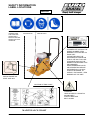
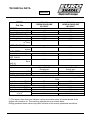
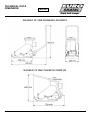
Murervej 5 P.O.Box 3024
DK-6710 Esbjerg V , Denmark
Tel:(+45) 75168411
Fax: (+45)75168412
E-mail:[email protected]
www.shatal.com
ENGLISH
OPERATING INSTRUCTIONS
& SPARE PARTS LIST
VIBRATORY PLATE COMPACTOR
MODEL PC 1112
ENGINE OPTIONS
M11600.F - 5HP
ROBIN GASOLINE ENGINE
M11600.E - 5.5HP
HONDA GASOLINE ENGINE
OCTOBER 2003
ENGLISH
INDEX OF CONTENTS
PAGE
CE DECLARATION OF CONFORMITY--------------------------------------------------------- 2
SAFETY INSTRUCTIONS ------------------------------------------------------------------------- 3-6
TECHNICAL DATA ---------------------------------------------------------------------------------- 7-8
OPTIONAL EXTRA ---------------------------------------------------------------------------------- 9
OPERATION-HONDA GX -160 & ROBIN EY-20
MANUAL START ------------------------------------------------------------------------------------- 10-14
APPLICATION ----------------------------------------------------------------------------------------- 15
MAINTENANCE --------------------------------------------------------------------------------------- 16-19
INSTRUCTIONS FOR ORDERING PARTS --------------------------------------------------- 20
BASE AND WHEEL ASSEMBLY ----------------------------------------------------------------- 21-22
BOX ASSEMBLY FOR ENGINE ROBIN EY-20 & HONDA GX-160 -------------------- 23-25
WATER SYSTEM ------------------------------------------------------------------------------------- 26-27
VULCALON PLATE ----------------------------------------------------------------------------------- 28-29
PC1112
-1-
OCT. 2003
ENGLISH
CE DECLARATION OF CONFORMITY
We hereby declare that the equipment described below conforms to the relevant fundamental
safety and health requirements of the appropriate CE Directives, both in its basic design and
construction. This declaration will cease to be valid if any modifications are made to the
machine without our expressed approval.
Product: Vibratory Plate Compactors : PC 1112
Relevant CE Machinery Safety Directives : (89/392/EEC)
amended by 91/368/EEC, 93/44/EEC, EN500-1, EN500-4.
Appropriate internal measures have been taken to ensure that series-production units
conform at all times to the requirements of current CE Directives and relevant standards.
The signatories are empowered to represent and act on behalf of the company’s management.
Murervej 5 P.O.Box 3024
DK-6710 Esbjerg V , Denmark
Tel:(+45) 75168411
Fax: (+45)75168412
E-mail:[email protected]
GENERAL MANAGER
NOVEMBER 2003
PC1112
-2-
OCT.2003
SAFETY INSTRUCTIONS
ENGLISH
Before starting, carefully read the engine maintenance and operating manual and
follow all the instructions.
Never operate the machine without the belt guard.
Keep hands and feet away from moving parts while the engine is running.
Do not operate the machine in closed places and inflammable environments.
Use unleaded fuel only.
Stop the engine before refilling the fuel tank. Never refuel near a naked flame or sparks
which could start a fire. Don’t smoke. Use only pure fuel and clean filling equipment.
Take care not to spill fuel.
Do not run the engine in a closed or badly ventilated room-danger of poisoning!
Before starting the engine, ensure that no one is in the danger area close to the engine
or equipment, and that all protective guards are fitted.
Operating the machine is advisable only with good lighting conditions.
Hearing protection must be worn.
Foot protection must be worn.
Do not touch hot surfaces.
PC 1112
-3-
OCT. 2003
SAFETY INSTRUCTIONS
ENGLISH
Medical preventive measures associated with regular to hand-arm vibration: Any operator
may have to expose his hands to vibratory tools should, prior to employment, be physically
examined and:
who
a. Previous history of exposure should be recorded.
b. All individuals who use vibrating equipment should be advised of the risk of exposure to
hand-arm vibration.
c. Persons with the following medical conditions should be carefully assessed before they
use vibrating equipment.
-
Primary Raynaud’s disease.
Disease causing implement of blood circulation to the hands.
Past injuries to the hand causing circulatory defects or deformity of bones and joints.
Other causes of secondary Raynaud’s phenomenon.
d. Provision should be made for the reporting of symptoms and arrangements made for
medical check-ups, at regular intervals of those at risk.
Advice to individuals who use vibrating hand tools as follows:
a. Wear adequate clothing to keep dry and maintain body core temperature at an acceptable
level, and, when possible, wear suitable gloves when using vibrating equipment.
Operator must wear safety shoes, safety glasses and special noise reducing headphones.
b. Avoid or minimize smoking while using vibratory equipment since nicotine reduce the
blood supply to the hands and fingers.
c. Should attacks of white or blue finger or long periods of tingling and/or numbness occur,
seek medical advice.
d. Inform appropriate work supervisor if abnormal vibration occurs.
Never allow anyone to operate this equipment without proper training.
Never leave machine running unattended.
Always close fuel valve on engines equipped with one when machine is not being operated.
Always store equipment properly when it is not being used.
Equipment should be stored in a clean, dry location out of the reach of children.
PC 1112
-4-
OCT. 2003
SAFETY INSTRUCTIONS
ENGLISH
Do not attempt to clean or service the machine while it is running.
Do not use gasoline or other types of fuels or flammable solvents to clean parts, especially
in enclosed areas.
Always replace worn or damaged components with spare parts supplied by Shatal.
PC 1112
-5-
OCT. 2003
SAFETY INFORMATION
LABEL LOCATIONS
ENGLISH
READ AND
UNDERSTAND
THE SUPPLIED
OPERATOR’S
MANUAL BEFORE
OPERATING THIS
MACHINE.
WEAR EAR
PROTECTION
WEAR EYE
PROTECTION
WEAR BOOTS
A NAMEPLATE LISTING THE
MODEL NUMBER, ITEM
NUMBER, IS ATTACHED TO
EACH UNIT.
PLEASE RECORD THE
INFORMATION FOUND ON
THIS PLATE SO IT WILL BE
AVAILABLE SHOULD THE
NAMEPLATE BECOME LOST
OR DAMAGED.
WHEN ORDERING PARTS
OR REQUESTING SEVICE
INFORMATION, YOU WILL
ALWAYS BE ASKED TO
SPECIFY THE MODEL, ITEM
NUMBER OF THE UNIT.
CHECK ENGINE OIL
LEVEL SAE 30W
CAUTION LIFTING POINT
WARNING!
HAND INJURE IF CAUGHT IN
MOVING BELT.
ALWAYS REPLACE
BELT GUARD
MAINTENANCE CHART
PC 1112
-6-
OCT. 2003
TECHNICAL DATA
ENGLISH
MODEL
Cat. No.
WEIGHT
Net Weight
Kg.
Operating Weight Kg.
COMPACTION DATA
Vibr. Frequency
Hz
Centrifugal Force
Kg.
Compaction Area
m2/hour
OPERATING DATA
Max. forward speed
m/min
CAPACITIES
Fuel tank
liters
Engine oil
liters
SAE 15W/40
Oil for exciter housing
liters
SAE 30
ENGINE
Model
Output
HP
Engine speed
rpm
NOISE AND VIBRATIONS
Noise level
Low idle
High idle
LpA=dB(A)
LpA=dB(A)
Low idle
LwA=dB(A)
High idle
LwA=dB(A)
Vibration values
a=m/s2
PC-1112
ROBIN GASOLINE
M11600.F
PC-1112
HONDA GASOLINE
M11600.E
71
73
71
73
93
1100
300
93
1100
300
26
26
3.8
0.6
3.6
0.6
0.13
0.13
Robin EY-20D
Recoil start
5HP
3600
Honda GX-160
Recoil start
5.5HP
3600
Sound pressure level at the operator’s ear according to ISO
6394
72
71
84
82
Sound power level according to ISO 5349(*)
75
76
89
88
The hand - arm vibration values according to ISO 5349
2. 4
2. 4
(*) The above noise level and vibration values were determined at normal speed of the
engine with vibration on. The machine was placed on an elastic base.
During operation these values may differ because of the actual operational conditions.
PC1112
-7-
OCT.2003
TECHNICAL DATA
DIMENSION
ENGLISH
HANDLE IN THE WORKING POSITON
HANDLE IN THE FOLDING POSITON
PC 1112
-8-
OCTO. 2003
OPTIONAL EXTRA
ENGLISH
NO.
1
2
3
PC 1112
DESCRIPTION
WATER TANK
VULCALON PLATE
CAGE
-9-
PART NO.
QTY.
P11805.E
P116280
115113
1
1
1
OCT. 2003
OPERATION-HONDA GX-160
ENGLISH
BEFORE STARTING:
1. Fill fuel tank.
2. Check oil level in engine crankcase and add if necessary.
3. Make sure that all dirt, mud, etc.are throughly removed from
the unit prior to operation. Special effort should be given
to the bottom face of the vibrating plate and those areas
adjacent to the cooling air inlet of engine and
air cleaner.
4. Make sure that all bolts are tightened properly. Loose bolts
may cause damage to the unit.
5. Check the V-belt for tightness. The normal slack should be
approximately 10 mm. when the belts are forcibly
depressed in the middle position between the two sheaves.
If there is excess belt play, there could be a decrease in the
impact force or erratic vibration, causing machine damage.
STARTING THE ENGINE:
1. Turn the fuel valve to the “ON” position.
2. Move the choke lever to the close position.
3. Move the throttle control lever slightly to the left.
4. Turn the engine switch to the on position.
PC 1112
-10-
OCT. 2003
OPERATION-HONDA GX-160
ENGLISH
5. Start the engine with recoil starter.
6. After starting the engine, return the chock lever gradually
to the full open position.
7. Allow the engine to warm up at idle speed for 3-5 minutes.
The warm-up procedure should particularly be followed in
cold weather. While the engine is warming up, check the
engine for fuel leaks or possible problems.
STOPPING:
1. Turn the engine switch to the OFF position.
2. Turn the fuel valve to the OFF position.
PC 1112
-11-
OCT. 2003
OPERATION-ROBIN EY20
ENGLISH
BEFORE STARTING:
1.
1. Fill fuel tank.
2. Check oil level in engine crankcase and add if necessary.
3. Make sure that all dirt, mud, etc.are throughly removed from
the unit prior to operation. Special effort should be given
to the bottom face of the vibrating plate and those areas
adjacent to the cooling air inlet of engine and
air cleaner.
4. Make sure that all bolts are tightened properly. Loose bolts
may cause damage to the unit.
5. Check the V-belt for tightness. The normal slack should be
approximately 10 mm. when the belts are forcibly
depressed in the middle position between the two sheaves.
If there is excess belt play, there could be a decrease in the
impact force or erratic vibration, causing machine damage.
STARTING THE ENGINE:
1. Turn the fuel valve to the “ON” position.
2. Move the choke lever to the close position.
PC 1112
-12-
OCT. 2003
OPERATION-ROBIN EY20
ENGLISH
3. Move the throttle control lever slightly to the right.
4. Turn the engine switch to the ON ( ▏)position.
5. Start the engine with recoil starter.
6. After starting the engine, return the chock lever gradually to
the full open position.
7. Allow the engine to warm up at idle speed for 3-5 minutes.
The warm-up procedure should particularly be followed in
cold weather. While the engine is warming up, check the
engine for fuel leaks or possible problems.
PC 1112
-13-
OCT. 2003
OPERATION-ROBIN EY20
ENGLISH
STOPPING:
1. Before shutting off the engine, allow the engine to idle
For 2-3 minutes.
2. Turn the engine switch to the OFF ({)position.
3. Close the fuel cock by moving the lever to the horizontal
position.
PC 1112
-14-
OCT. 2003
APPLICATION
ENGLISH
APPLICATION:
1. This plate compactor is designed for compacting loose, granular soils, gravel, and paving stones.
2. Compactors equipped with water tanks are designed for compacting asphalt.
3. Operate the compactor only at full throttle.
4. Let the compactor progress at its normal speed while guiding it in a straight line.
5. Three or four passes depending on the material are normally required to achieve the best
compaction.
6. The soil must be moist to achieve the best compaction.
7. It must not be too wet nor too dry so that dust is created.
8. Do not operate the compactor on hard surfaces or concrete.
9. Attach a polyureathane plate under the compactor when compacting paving stones.
10. Fill the water tank with water and open the water flow valve when compacting asphalt.
PC 1112
-15-
OCT. 2003
MAINTENANCE
ENGLISH
TROUBLESHOOTING
Problem / Symptom
Reason / Remedy
Compactor advances slowly or •
poor compaction
•
•
•
Engine throttle control not fully open.
Soil is too wet so that the plate is sticking.
Drive belt is loose or worn. Adjust or replace belt.
Air filter is clogged with dust, reducing engine performance.
Clean or replace air filter.
• Engine speed too low. Adjust or repair engine so that it runs at the
correct speed.
Engine running but no plate
vibration
•
•
•
•
•
Plate jumps or
compacts unevenly
• Ground surface too hard.
• Defective antivibration mountings – check antivibration mounting
Engine throttle not open.
Drive belt loose or broken. Adjust or replace.
Clutch demaged. Inspect and replace clutch.
Engine speed too low. Check engine speed.
Too much oil in exciter. Remove oil to correct level.
and replace if necessary.
STORAGE
-
Clean base plate.
Clean engine cylinder cooling fins.
Clean or replace air filter.
Change exciter oil.
Change engine oil and follow procedures described in engine manual for engine storage.
Cover machine and store in a clean, dry place.
PC 1112
-16-
OCT. 2003
MAINTENANCE
ENGLISH
PERIODIC MAINTENANCE SCHEDULE
The chart below lists basic engine maintenance. Refer to engine manufacturer’s Operation
Manual for additional information on engine maintenance.•
Daily
before
starting
Check fuel level and fill.
Check engine oil level and top up.
Inspect fuel lines.
Inspect air filter. Replace as needed.
Check and adjust drive belt.
Clean air cleaner elements.
Inspect shockmounts for damage.
Change engine oil.
Clean cooling system.
Clean sediment cup / fuel filter.
Check and clean spark plug.
Check and adjust valve clearance.
Change exciter oil.
After
first
20 hrs.
Every
2 weeks
or
50 hrs.
•
•
•
•
Every
month
or
100 hrs.
Every
year
or
300 hrs.
•
•
•
•
•
•
•
•
•
•
•
CLEANING COMPACTOR
-
Remove all dirt, stones etc.from the compactor after each day of operation.
Keep engine fins clean.
PC 1112
-17-
OCTO. 2003
MAINTENANCE
ENGLISH
LIFTING MACHINE
TO LIFT MACHINE MANUALLY:
-
Stop the engine.
Obtain help from a partner and plan the lift.
Hold the machine by its operating handle and lifting handle (A).
Lift the machine as shown.
Lift machine carefully with the correct posture.
INSTRUCTIONS FOR LIFTING MACHINE
LIFTING HOOK
Never walk or stand under a machine being
lifted.
Use only the operating handle (1) for lifting
the machine.
Use only tested and authorised lifting
equipment. Before lifting check that vibration
damper (2) and protecting frame are
correctly attached and not damaged.
PC 1112
- 18 -
OCT. 2003
MAINTENANCE
ENGLISH
TRANSPORTING
To avoid burns or fire hazards,let engine cool before transporting machine or storing indoors.
Turn fuel valve to the off position and keep the engine level to prevent fuel from spilling.
Tie the machine to the vehicle to prevent sliding or tipping over.
PC 1112
- 19 -
OCT. 2003
INSTRUCTIONS FOR
ORDERING PARTS
ENGLISH
Please State Machine Details in the Following Sequence:
•
•
•
Machine Serial Number
Part Number, Description and Quantity of Parts
Full Delivery Address
Manufacturers Liability and the Use of Genuine Spare Parts
Liability for this machine is accepted only when the machine is defective from the outset.
Liability is reduced or nullified in the event that the user fails to comply with the operating
and maintenance instructions and uses spare parts which are not guaranteed.
Contents
Base and Wheel Assembly ------------------------------------------------------------------ 21
Box Assembly for Engine Robin EY20 & Honda GX160 ----------------------------- 23
Water System ------------------------------------------------------------------------------------ 26
Vulcalon Plate ------------------------------------------------------------------------------------ 28
PC 1112
-20-
OCT. 2003
11
10
12
9
13
14
8.1
15
16
17
8
18
19
20
22
21
7
6
23
5
24
25
26
27
4
3
VIBRATORY PLATE COMPACTOR
PC-1112
BASE AND WHEEL ASSEMBLY
2
1
FIRST EDITION-OCTOBER2003
(SEE PARTS LIST PAGE-22)
-21-
ENGLISH
SPARE PARTS LIST
BASE AND WHEEL ASSEMBLY
PC-1112
NO.
DESCRIPTION
1
2
3
STAR LOCK 20
WHEEL Ø 200 (8”)
AXLE ASSEMBLY WITH
QUICK RELEASE
(WHEEL NOT INCLUDED)
BASE PLATE WITH ECCENTRIC
HOUSE
HEXAGON HEAD SCREW
DIN 933-M12X35
SPRING WASHER 127B -12
WASHER Ø40XØ12.5X3.
118435
51700
116430
2
2
1
15
16
17
ECCENTRIC SHAFT
SHAFT KEY 8X7X25
BALL BEARING 6309.C3
11701
32198
P50938
1
1
1
116269
1
18
OIL SEAL Ø40X Ø52X7
B40033900
1
/
4
19
O-RING Ø100X3
11828
1
/
/
4
4
20
21
11804
118914
1
4
40527
2
22
118915
4
40527.1
2
23
128940
2
/
4
24
P51119
1
10
11
12
ANTI VIBRATION MOUNTING
40 SCHOR
ANTI VIBRATION MOUNTING
60 SCHOR
HEXAGON HEAD SCREW
DIN 933-M8X20
SPRING WASHER 127B -8
REAR COVER
O-RING Ø100X3
FRONT COVER
HEXAGON SOCKET COUNTERSUNK
HEAD SCREW DIN 7991-M8X20
COUNTERSUNK SERRATED LOCK
WASHER DIN6798-M8
HEXAGON SOCKET SET SCREW
DIN 913-M6X10
PULLEY Ø95X1SPZ.
/
11805
11828
4
1
1
25
26
27
/
116901
/
1
1
1
13
14
BALL BEARING 6309.C3
OIL PLUG 3/8” B.S.P
P50938
11729
1
2
4
5
6
7
8
8.1
9
PC 1112
PART NO. QTY.
NO.
-22-
DESCRIPTION
WASHER Ø40X Ø10.5X3
LOCKING DISC SPRING M10
HEXAGON HEAD SCREW
DIN 933-M10X20
PART NO. QTY.
MAY.2003
9.1
9
10
11
12
5 5.1
13
14
4
15
3
2
20
22 23 24
21
1
16
17
18
19
36
34
25
37
33
26
27
VIBRATORY PLATE COMPACTOR
PC-1112
BOX ASSEMBLY FOR ENGINES
ROBIN EY20 & HONDA GX160
(SEE PARTS LIST PAGES-24;25)
35
28
29
-23-
30
31
32
FIRST EDITION-OCTOBER2003
ENGLISH
DESCRIPTION
NO.
PART NO.
QTY.
NO.
116415
1
14
HEXAGON HEAD SCREW
DIN 933-M8X20
BELT GUARD
WASHER Ø30X Ø10.5X3
SPRING WASHER 127B – 10
HEXAGON HEAD SCREW
DIN 933-M10X20
HEXAGON HEAD SCREW
DIN 933-M10X15
HEXAGON HEAD SCREW
DIN 933-M10X60
HEXAGON NUT DIN934-M10
HEXAGON HEAD SCREW
DIN 933-M10X20
SPRING WASHER 127B - 10
1
HANDLE
2
3
4
5
WASHER Ø21X Ø8.4X3
SPRING WASHER 127B - 8
HEXAGON NUT DIN934-M8
ROBIN GASOLINE EY -20 (5HP)
/
/
/
I 50355.M
4
4
4
1
15
16
17
18
5.1
HONDA GASOLINE GX -160(5.5HP)
I 50200.M
1
19
/
1
20
90741-883-810
508975.Z
1
1
21
22
P50745.D
1
23
/
116900
1
1
24
25
9
9.1
10
KEY FOR ROBIN EY-20
3/16”X3/16”X1¾”
KEY FOR HONDA GX160
V-BELT SPZ-LA975
11
CENTRIFUGAL CLUTCH PULLEY
SPARE PARTS LIST
BOX ASSEMBLY FOR ENGINE
ROBIN EY20 & HONDA GX160
PC-1112
DESCRIPTION
PART NO.
QTY.
/
1
115164
/
/
/
1
2
2
1
/
1
/
1
/
/
1
1
/
1
/
/
1
4
BORE 20X Ø138X1SPZ
12
13
WASHER Ø30X Ø9 X3
LOCKING DISC SPRING M8
PC 1112
- 24 -
WASHER Ø30X Ø10.5X3
HEXAGON HEAD SCREW
DIN 933-M12X25
MAY.2003
ENGLISH
NO.
26
27
28
29
30
31
32
DESCRIPTION
SPRING WASHER 127B - 12
ENGINE BOX
ENGINE BOLT BRACKET
HEXAGON HEAD SCREW
DIN 933-M12X70
WASHER Ø40X Ø12.5X3
OKOLON BEARING
STEEL BUSH
PC 1112
PART NO.
QTY.
NO.
/
116325
11721
/
4
1
2
2
33
34
35
36
/
31124
11810
2
4
2
37
- 25 -
SPARE PARTS LIST
BOX ASSEMBLY FOR ENGINE
ROBIN EY20 & HONDA GX160
PC-1112
DESCRIPTION
PART NO.
QTY.
RUBBER BUFFER
SELF LOCKING NUT M8
SELF LOCKING NUT M12
LOCKING PIN WITH THREAD
115320
/
/
11855.1
2
2
2
1
HEXAGON NUT M20X10
116905
1
MAY.2003
16
15
14
1
13
12
11
2
3
4
5
6
7
8
10
9
VIBRATORY PLATE COMPACTOR
PC 1112
WATER SYSTEM (OPTIONAL)
(SEE PARTS LIST PAGE-27)
-26-
FIRST EDITION - OCTOBER 2003
SPARE PARTS LIST
WATER SYSTEM
( OPTIONAL )
ENGLISH
NO.
1
2
3
4
5
6
7
8
9
10
11
12
13
14
15
16
NOTE:
PC 1112
DESCRIPTION
PART NO.
QTY.
WATER TANK
BALL VALVE 3/8” B.S.P
ELBOW HOSE CONNECTOR Ø3/8”
PLASTIC HOSE Ø 3/8”
WATER PIPE
RUBBER PLUG FOR WATER PIPE
HEXAGON HEAD SCREW DIN 933-M10X25
SELF LOCKING NUT M10
HEXAGON HEAD SCREW DIN 933-M8X25
SPRING WASHER 127B -8
CAGE
HEXAGON HEAD SCREW DIN 933-M8X25
SPRING WASHER 127B -8
WASHER Ø21XØ8.5X2.5
WATER TANK HOLDER
RUBBER PLUG
115170
30507
30902.4
311937
116710
11829
/
/
/
/
115113
/
/
/
117724
30322
1
1
1
0.4m
1
2
2
2
4
4
1
4
4
4
2
1
WATER TANK COMPLETE
P11805.E
- 27 -
OCT. 2003
4
3
2
1
VIBRATORY PLATE COMPACTOR
PC1112
VULCALON PLATE (OPTIONAL)
(SEE PARTS LIST PAGE-29)
-28-
FIRST EDITION-OCTOBER 2003
SPARE PARTS LIST
VULCALON PLATE
( OPTIONAL )
ENGLISH
NO.
1
2
3
4
PC 1112
DESCRIPTION
VULCALON PLATE
PLATE
HEXAGON HEAD SCREW DIN 933-M10X45
SELF LOCKING NUT M10
-29-
PART NO.
QTY.
116280
116281
/
/
1
1
2
2
OCT. 2003
Murervej 5 P.O.Box 3024
DK-6710 Esbjerg V , Denmark
Tel:(+45) 75168411
Fax: (+45)75168412
E-mail:[email protected]
www.shatal.com
PURCHASE ORDER
PC1112 VIBRATORY PLATE COMPACTOR
FAX YOUR SPARE PARTS REQUIREMENTS
TO THE NEAREST SERVICE STATION.
COMPANY’S NAME: --------------------------------------------------------------------------------------------------------ADDRESS: ---------------------------------------------------------------------------------------------------------------------COUNTRY: ---------------------------------------------------------------------------------------------------------------------TELEPHONE: -----------------------------------------------------------------------------------------------------------------FAX: -----------------------------------------------------------------------------------------------------------------------------MACHINE SERIAL NO: -------------------------------------------------------------------------------------------------------
NO.
PART NO.
SHIPPING METHODS:
DESCRIPTION
BY AIR
QTY.
BY SURFACE
REMARKS
BY SEA
SENDER’S NAME: -----------------------SIGNATURE: --------------------------------