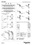
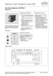
1
Bedienungs- und Montageanleitung
Installation and Operating Instructions
SCR 4-W22-3.5-D
607.5111.009
Bedienungs- und
Montageanleitung
Sicherheitsschaltgerät für NOT-AUSund Schutztüranwendungen
Installation and Operating
instruction
Safety controller for E-STOP and
safety guard monitoring applications
Zielgruppe/
Target group
Einleitung
Introduction
Diese Bedienungs- und Montageanleitung soll Sie mit dem NOT-AUS Sicherheitsrelais und Schutztürwächter
SCR 4-W22-3.5-D vertraut machen.
This installation and operating instruction
shall make you familiar with the emergency stop and safety guard monitoring
relay SCR 4-W22-3.5-D.
Die Bedienungsanleitung richtet sich an
folgende Personen:
The operating instruction is addressed to
the following persons:
Zeichenerklärung/
Signs and symbols
Qualifizierte Fachkräfte, die Sicherheitseinrichtungen für Maschinen und
Anlagen planen und entwickeln und
mit den Vorschriften über Arbeitssicherheit und Unfallverhütung vertraut
sind.
Qualifizierte Fachkräfte, die Sicherheitseinrichtungen in Maschinen und
Anlagen einbauen und in Betrieb
nehmen.
In dieser Bedienungsanleitung werden
einige Symbole verwendet, um wichtige
Informationen hervorzuheben:
Dieses Symbol steht vor Textstellen, die
unbedingt zu beachten sind. Nicht Beachtung führt zur Verletzung von Personen oder zu Sachschäden.
Dieses Symbol kennzeichnet Textstellen,
die wichtige Informationen enthalten.
⇒
Dieses Zeichen kennzeichnet auszuführende Tätigkeiten.
Nach diesem Zeichen wird beschrieben,
wie sich der Zustand nach einer ausgeführten Tätigkeit ändert.
Qualified professionals who plan and
develop safety equipment for machines and plants and who are familiar with the regulations for occupational safety and accident prevention.
Qualified professionals, who install
safety equipment into machines and
plants and put them into operation.
This operating instruction contains several symbols which are used to highlight
important information:
This symbol is placed in front of text
which has to be strictly noticed.
Nonobservance leads to serious injuries
or damage to property.
This symbol is placed in front of text,
which contains important information.
This sign marks operations to be executed.
After this sign follows a description on
how the status has changed after execution of the operation.
Subject to technical modifications, all information are supplied without liability.
Ausgabedatum/Date of issue: 21.06.2005 / Seite/Page 1 von/of 9
Technische Änderungen vorbehalten, alle Angaben ohne Gewähr.
Dokument/Document: 0800000434_01.doc / Stand/Updated: 1/Mittlg./Published 0368-05
Bernstein AG, Tieloser Weg 6, D-32457 Porta Westfalica / www.bernstein-ag.de
Vorlage/Template: 0850174292 Orig. 2
Bedienungs- und Montageanleitung
Installation and Operating Instructions
Bestimmungsgemäße
Verwendung
Intended Use
Sicherheitshinweise
Safety instructions
Das Sicherheitsrelais SCR 4 ... ist bestimmt für den Einsatz in:
Einkanalige und zweikanalige Schaltungstechnik für NOT-AUS oder
Schutztürüberwachungen
ohne Überwachung des StartTasters
The safety relay SCR 4… is determined
for the use in:
Single and dual-channel control circuits for monitoring EMERGENCYSTOP devices or safety guards
without monitoring the STARTbutton
Personen - und Sachschutz sind nicht
mehr gewährleistet, wenn das Sicherheitsrelais nicht entsprechend seiner
bestimmungsgemäßen Verwendung
eingesetzt wird.
Personnel protection and the protection
of goods are no longer guaranteed if the
safety-relay is not applied according to its
intended use.
Beachten Sie unbedingt die folgenden
Punkte:
Please strictly note the following points:
Zu Ihrer Sicherheit
For your safety
Das Gerät darf nur unter Beachtung
dieser Betriebsanleitung von Fachpersonal installiert und in Betrieb genommen werden, das mit den geltenden Vorschriften über Arbeitssicherheit und Unfallverhütung vertraut
ist. Elektrische Arbeiten dürfen nur
von Elektrofachkräften durchgeführt
werden.
Beachten Sie die jeweils gültigen
Vorschriften, insbesondere hinsichtlich der Schutzmaßnahmen.
Reparaturen, insbesondere das Öffnen des Gehäuses, dürfen nur vom
Hersteller oder einer von ihm beauftragten Person vorgenommen werden. Ansonsten erlischt jegliche Gewährleistung.
Vermeiden Sie mechanische Erschütterungen beim Transport oder
im Betrieb; Stöße größer 5g / 33Hz
können zur Beschädigung des Gerätes führen.
Montieren Sie das Gerät in einem
staub- und feuchtigkeitsgeschützten
Gehäuse; Staub und Feuchtigkeit
können zu Funktionsstörungen führen.
Sorgen Sie für eine ausreichende
Schutzbeschaltung bei kapazitiven
und induktiven Lasten an den Ausgangskontakten.
In regelmäßigen Zeitabständen sollte
das NOT-AUS Relais ausgelöst werden und auf richtige Funktion geprüft
werden (mindestens jedes halbe Jahr
oder im Wartungszyklus der Anlage).
The device shall only be installed
and operated by persons, who are
familiar with the regulations for occupational safety and accident prevention.
Electric work shall only be carried out
by qualified personnel.
Follow the applicable regulations in
particular regarding the protective
measures.
Repair work and especially opening
the enclosure may only be carried
out by the manufacturer or an authorized representative.
Otherwise any guarantee is void.
Avoid mechanical vibrations during
transport and operation. Shocks
greater than 5 g / 33 Hz may lead to
damage of the device.
The device shall be panel mounted in
an enclosure rated at IP 54 or better,
otherwise moisture or dust can lead
to malfunctions.
Adequate fuse protection must be
provided on all output contacts with
capacitive and inductive loads.
The emergency stop relay shall be
test in regular time intervals (at least
every six month or along with the
maintenance cycle of the installation).
Subject to technical modifications, all information are supplied without liability.
Ausgabedatum/Date of issue: 21.06.2005 / Seite/Page 2 von/of 9
Technische Änderungen vorbehalten, alle Angaben ohne Gewähr.
Dokument/Document: 0800000434_01.doc / Stand/Updated: 1/Mittlg./Published 0368-05
Bernstein AG, Tieloser Weg 6, D-32457 Porta Westfalica / www.bernstein-ag.de
Vorlage/Template: 0850174292 Orig. 2
Bedienungs- und Montageanleitung
Installation and Operating Instructions
Aufbau und Funktionsweise
A1 A2
(+) (-)
Assembly and function
(function circuit diagram)
S33 S34 S11S12 S21 S22
13 23 33
41
14 24 34
42
elektr. Sicherung
electr. fuse
Transformator
transformer
~
~
~
K1
Überwachungslogik /
monitoring logic
=
K2
+
K1
K2
Ausgangskontakte:
Output contacts:
13-14, 23-24, 33-34
Sicherheitsstrompfade (Schließer)
safety circuits
(normally open)
41-42
Signalisierungsstrompfad (Öffner)
auxiliary circuits
(normally close)
Start-Taster
START button
NOT-AUS Kanal 1 und 2
EMERGENCY-STOP channel 1 and 2
Für das Betreiben des Gerätes muss
eine Hilfsspannung an die Klemmen A1
und A2 angelegt werden. Die LED ‘Power‘ leuchtet.
The supply voltage must be applied at
terminals A1 and A2. The ‘Power‘ LED
illuminates.
Die Anschlussklemmen S11, S12, S21
und S22 werden nach den entsprechenden Anwendungsbeispielen beschaltet.
Terminals S11, S12, S21 and S22 have
to be wired up as shown in the corresponding application examples.
Zum START des Gerätes muss die
Klemme S33 mit S34 über einen Schließerkontakt überbrückt werden.
To START the device, terminals S33 and
S34 must be bridged with a normally
open contact. The device operates when
you close this contact.
Danach sind die Kontakte 13-14, 23-24,
33-34 geschlossen, der Kontakt 41-42
geöffnet. Die LED´s ‘Channel 1‘ und
‘Channel 2‘ leuchten.
After that the contacts 13-14, 23-24 and
33-34 are closed, contact 41-42 is
opened. The LED’s ‘Channel 1‘ and
‘Channel 2‘ illuminate.
In Reihe zu dem START-Taster kann
die Schaltung eines externen
Schützes überwacht werden
(siehe Anwendungsbeispiel 3).
Connected in series to the START-button
the circuit of an external contactor can be
monitored. (see application example 3).
S33-S34
S11-S12, S21-S22
Subject to technical modifications, all information are supplied without liability.
Ausgabedatum/Date of issue: 21.06.2005 / Seite/Page 3 von/of 9
Technische Änderungen vorbehalten, alle Angaben ohne Gewähr.
Dokument/Document: 0800000434_01.doc / Stand/Updated: 1/Mittlg./Published 0368-05
Bernstein AG, Tieloser Weg 6, D-32457 Porta Westfalica / www.bernstein-ag.de
Vorlage/Template: 0850174292 Orig. 2
Bedienungs- und Montageanleitung
Installation and Operating Instructions
Installation and initial operation
Für eine sichere Funktion muss das Sicherheitsrelais in ein staub- und feuchtigkeitsgeschütztes Gehäuse eingebaut
werden (IP54).
The device should be panel mounted in
an enclosure rated at IP 54 or better,
otherwise moisture or dust can lead to
malfunction.
Führen Sie die Verdrahtung entsprechend des Verwendungszweckes durch.
Orientieren Sie sich dabei an den Anwendungsbeispielen. Generell ist das
Sicherheitsrelais nach folgenden Angaben zu verdrahten:
Carry out the wiring according to the
intended the use. Follow the application
examples.
In general the safety-relay has to be
wired acc. to the following instructions:
1. Aktivierungs- und Rückführungskreis
schließen
Automatische Aktivierung:
1. Close the feedback control loop and
the activation circuit
Automatic activation:
Montieren Sie das Sicherheitsrelais auf eine Normschiene.
Elektrischer
Anschluss
Electrical
connection
Attach the safety-relay to a DINRail.
Brücken Sie die Anschlussklemmen
S33-S34
Conditional activation:
Bedingte Aktivierung:
Bridge terminals S33-S34
START-Taster an S33S34 anschließen (keine
Brücke an S33-S34). Externe Schütze werden in
Reihe zum STARTTaster an die Klemmen
S33-S34 angeschlossen.
Connect START button to S33S34 (no bridge on S33-S34).
N.C. contacts of external contactors are wired in series with the
START-button at the terminals
S33-S34.
Start
Start
S33 S34
S33 S34
SAFE 4
SAFE 4.1
Start über Start-Taste
with start control
.
automatischer Start
without start control
K1 ext
Mechanical
installation
Montage und Inbetriebnahme
K2 ext
Mechanische
Montage
S33 S34
Start über Start-Taste und Anschluß
Maschinenfreigabekreise / Schützkontrolle
Start with start bottom and detection of external
conductors
Subject to technical modifications, all information are supplied without liability.
Ausgabedatum/Date of issue: 21.06.2005 / Seite/Page 4 von/of 9
Technische Änderungen vorbehalten, alle Angaben ohne Gewähr.
Dokument/Document: 0800000434_01.doc / Stand/Updated: 1/Mittlg./Published 0368-05
Bernstein AG, Tieloser Weg 6, D-32457 Porta Westfalica / www.bernstein-ag.de
Vorlage/Template: 0850174292 Orig. 2
Bedienungs- und Montageanleitung
Installation and Operating Instructions
2. Close input circuit
2. Eingangskreis schließen
Einkanalig: Schließen Sie
den Kontakt des Auslöseelementes an die positive
Versorgungsspannung und
die Anschlussklemme A1(+)
an.
Single-channel: Connect
contacts from trigger element
to positive supply voltage
and A1(+).
Dual-channel: connect the
contacts from the safety
switching device safety
switching device to S11-S12
andS21-S22.
Zweikanalig: Schließen Sie
die Kontakte des Sicherheitsschaltgerätes an S11S12 und S21-S22 an.
24 VAC/DC
Auslöseelement /
trigger
element
Auslöseelement /
trigger
element
S11
A1 (+)
A2 (-)
einkanalig / single-channel
Die Verdrahtung der Versorgungsspannung ist abhängig
vom Gerätetyp ( siehe Typenschild am Gerät).
3. Versorgungsspannung Uv:
24V AC/DC oder 115V AC, 230V AC
Einkanalig: Schließen Sie die
Versorgungsspannung
Uv (+) / L (Phase) über den
Sicherheitskontakt des NOTAUS bzw. Schutztürschalters
an die Klemme A1(+) an.
Schließen Sie den Uv(-) /
UvN (Nullleiter) direkt an die
Klemme A2(-) an.
Bei 115V und 230V-Geräten
muss der Erdanschluss an
S21 angeschlossen werden.
Zweikanalig: Schließen Sie
die Versorgungsspannung an
die Klemmen A1(+) und A2(-)
an.
Beachten Sie unbedingt die maximalen
Leitungslängen!
S12
S22
S21
zweikanalig / dual-channel
The wiring of the supply voltage is
dependent on the device version
(see type plate on the device)
3. Supply voltage Uv:
24V AC/DC or 115V AC, 230V AC
Single channel: The supply
voltage Uv (+) / L has to be
routed over the safety contact from the E-STOP / safety
guard switch to terminal
A1(+). Connect Uv(-) / UvN
(neutral wire) directly to terminal A2(-).
With 115V and 230V devices
the ground wire has to be
connected to S21.
Dual-channel: The supply
voltage has to be connected
to the terminals A1(+) and
A2(-).
Please strictly note the max. length of the
cables!
Subject to technical modifications, all information are supplied without liability.
Ausgabedatum/Date of issue: 21.06.2005 / Seite/Page 5 von/of 9
Technische Änderungen vorbehalten, alle Angaben ohne Gewähr.
Dokument/Document: 0800000434_01.doc / Stand/Updated: 1/Mittlg./Published 0368-05
Bernstein AG, Tieloser Weg 6, D-32457 Porta Westfalica / www.bernstein-ag.de
Vorlage/Template: 0850174292 Orig. 2
Bedienungs- und Montageanleitung
Installation and Operating Instructions
Erdschluss bei
AC - DC-Variante
(mit elektr. Sicherung) /
Earth fault
AC / DC-version
(with electronic fuse
protection)
Fehlfunktion der
Kontakte /
Contact malfunction
Nur eine oder
keine LED brennt /
Only one or no
LED illuminates
Wartung und Reparatur
Maintenance and repair
Das Sicherheitsrelais arbeitet wartungsfrei. Eine Reparatur durch den Anwender
ist nicht zulässig.
The safety-relay operates maintenancefree. Any repair work carried out by the
user is not permitted.
Zum Austausch des Gerätes empfehlen
wir die Kabel 1 zu 1 abzuschrauben und
an das Austauschgerät anzuschrauben.
For exchange of the device, we advise to
unscrew the cables “1 to 1” from the defective device and to screw them in place
again on the exchange-device.
1. Kabel abschrauben und an dem Austauschgerät anschrauben.
1.
You must screw of the cable and
screw on the exchange-device.
2. Defektes Gerät von der Hutschiene
nehmen.
2.
Take away the defective device
from the DIN-Rail.
3. Austauschgerät auf Hutschiene montieren.
3.
Mount the exchange device on
the DIN-Rail.
Fehler/Störungen, Auswirkung
und Maßnahmen
Faults, effects and measures
Die Sicherung löst aus. Die Ausgangskontakte öffnen. Nach Wegfall der Störursache und Einhalten der Betriebsspannung ist das Gerät wieder betriebsbereit.
The electronic fuse releases. The output
contacts open. Once the cause of the
failure is removed and the supply voltage
is observed, the device is ready for operation.
Bei verschweißten Kontakten ist nach
Öffnen des Ausgangskreises keine neue
Aktivierung möglich.
Externer Beschaltungsfehler oder interner Fehler. Externe Beschaltung prüfen.
Wenn Fehler immer noch vorhanden,
Gerät an BERNSTEIN AG einschicken.
In case of welded contacts and next to
opening of the input circuit a further activation is not possible.
An external wiring fault or an internal fault
is present. Verify the external wiring.
When the fault is still present, send the
device to BERNSTEIN AG.
Subject to technical modifications, all information are supplied without liability.
Ausgabedatum/Date of issue: 21.06.2005 / Seite/Page 6 von/of 9
Technische Änderungen vorbehalten, alle Angaben ohne Gewähr.
Dokument/Document: 0800000434_01.doc / Stand/Updated: 1/Mittlg./Published 0368-05
Bernstein AG, Tieloser Weg 6, D-32457 Porta Westfalica / www.bernstein-ag.de
Vorlage/Template: 0850174292 Orig. 2
Bedienungs- und Montageanleitung
Installation and Operating Instructions
Technische Daten / Technical Data
Elektrische Daten
/ Electrical data
Versorgungsspannung Uv / supply voltage
Spannungsbereich
/ voltage range
Frequenz (AC-Variante) / frequency (AC-type)
Leistungsaufnahme ca. / power consumption appr.
Leitungsdaten
/ Conductor data
Leiteranschluß
/ conductor connection
Max. Leitungslängen (Eingangskreis) /
max. conductor length (input circuit)
Leiterquerschnitt
/ conductor cross-section
Kapazität
/ capacity
Temperatur
/ temperature
Kontaktdaten
Version 24V AC/DC or Version 230V AC or Version 110V AC.
0,90 ...1,1 Uv
50 ... 60 Hz
110/230V: ca. 3,7 VA, 24V DC: 3 W, 24V AC: 5 VA
2
2 x 1,5 mm Massivdraht / solid wire
2
2 x 1,5 mm Litze mit Hülse / strand with wire end ferrule
DIN VDE 46228
2 x 100m ( einkanalig / single channel)
4 x 100m ( zweikanalig / dual channel)
2
2 x 1,5 mm / 4 x 1,5mm²
150 nF/km
+ 25°C / +77°F
/ Contact data
Kontaktbestückung / contact configuration
Kontaktart
/ contact type
Kontaktmaterial
/ contact material
Schaltspannung
/ switching voltage
Schaltstrom
/ switching current
Max. Schaltvermögen / max. switching capability
DIN EN 60947-5-1
Schaltleistung max. / max. switching capacity
Mechanische Lebensdauer / mechanical life
Elektrische Lebensdauer
/ electrical life
Kriech- und Luftstrecken
/ creapage and
clearance distances
Kontaktabsicherung / contact protection
Wiederbereitschaftszeit / ready after time delay
Rückfallverzögerung K1/delay on deenergisation K1
3 Schließer / 1 Öffner
3 N.O. contacts / 1 N.C. contact
Relais zwangsgeführt
/ relay forcibly guided contacts
AgSnO2 oder vergleichbares Material /
AgSnO2 or comparable material
230V AC, 24V DC
5A
AC 15 230 V / 5 A
DC 13 24 V / 5 A
1250 VA (ohmsche Last) / 1250 VA (ohms load)
7
10 Schaltspiele / operations
5
10 Schaltspiele / operations (DC 24V/2A)
-DIN VDE 0160
für Verschmutzungsgrad 2,
Überspannungskategorie 3 / 250 V
DIN VDE 0160
at pollution grade 2,
over voltage category 3 / 250 V
-Basisisolierung:
Überspannungskategorie 3 / 250 V
basis isolation:
over voltage category 3 / 250 V
Schließer: 6,3A flink / NO contact: 6,3A brisk
Öffner: 4A Neozed gL/gG / NC contact: 4A Neozed gL/gG
< 1s
< 30 ms, 24V AC: < 50ms
Mechanische Daten / Mechanical data
Gehäusematerial
/ enclosure material
Polyamid / polyamide PA 6.6
Abmessungen (BxHxT) in mm/dimensions ( WxHxD ) 22,5 x 114,5 x 99
Befestigung
/ mounting
Schnappbefestigung für Normhutschiene / click-fastening for DINRail
Luftfeuchtigkeit / air humidity
Wechselklima, swap climate, 95%, 0 ... +50°C / +32 ... +122°F
Umgebungsdaten
/ Environmental data
Umgebungstemperatur/ operating temperature range
Schutzart Klemmen / degree of protection, terminals
Schutzart Gehäuse / degree of protection, enclosure
Stoßfestigkeit Schließer/Öffner / shock resistance
N.O./N.C. contacts
-25°C ... +55°C / -13°F … +131°F
IP 20 DIN VDE 0470 Teil 1 / part 1
IP 40 DIN VDE 0470 Teil 1 / part 1
8g / 2g
CE Konformität / Conformity
Zulassungen / Approvals
ja / yes
TÜV, UL, C-UL
Subject to technical modifications, all information are supplied without liability.
Ausgabedatum/Date of issue: 21.06.2005 / Seite/Page 7 von/of 9
Technische Änderungen vorbehalten, alle Angaben ohne Gewähr.
Dokument/Document: 0800000434_01.doc / Stand/Updated: 1/Mittlg./Published 0368-05
Bernstein AG, Tieloser Weg 6, D-32457 Porta Westfalica / www.bernstein-ag.de
Vorlage/Template: 0850174292 Orig. 2
Bedienungs- und Montageanleitung
Installation and Operating Instructions
Anwendungsbeispiele 1-6
(ohne Überwachung des START- Tasters)
Ub
NOTAUS/
ESTOP
START
S33 S34
A1(+) A2(-) S21 S22 S11 S12 13 23 33 41
Bis Steuerungskategorie 2
Up to control category 2
Siehe Hinweis auf Seite 9
See note on page 9
24V AC/DC
NOTAUS/
ESTOP
START
S33
S34
A1(+) A2(-)
S21
S22
S11
S12
23
13
33
41
Bis Steuerungskategorie 4
Up to control category 4
U ext.
S ext.
K2 ext.
K1 ext.
NOTAUS/
ESTOP
S33
S34
A1(+) A2(-)
S21
S22
S11
S12
13
23
14
24
33
41
K2 ext.
K1 ext.
Bis Steuerungskategorie 4
Up to control category 4
24V AC/DC
Example 1: EMERGENCY-STOP circuit
(without opposite polarity between
channels).
Mit dem Starttaster wird das Gerät aktiviert. Die Kontakte 13-14, 23-24 und 3334 schließen. Über den NOT-AUS- Taster fallen die Kontakte in ihre Grundstellung zurück.
Pressing the START-button, the device
will be activated. The contacts 13-14, 2324 and 33-34 close. Pressing the
EMERGENCY-Stop button initiates a
stop and the output contacts open.
Beispiel 2: Zweikanalige NOT-AUSSchaltung (mit Querschlusssicherheit).
Example 2: Dual-channel
EMERGENCY-STOP circuit (with opposite polarity between channels)
Bei der zweikanaligen NOT-AUS- Schaltung mit Querschlusssicherheit wird der
Klemmenanschluss S11, S12, S21 und
S22 verwendet. Mit dem START-Taster
wird das Gerät aktiviert. Die Kontakte 1314, 23-24 und 33-34 schließen. Über den
NOT-AUS- Taster fallen die Kontakte in
ihre Grundstellung zurück.
For this application the terminal wiring
S11, S12, S21 and S22 must be used.
With the START-button the device will be
activated The contacts 13-14, 23-24 and
33-34 are closed. Pressing the EMERGENCY-Stop button initiates a stop and
the output contacts open.
Beispiel 3: Zweikanalige NOT-AUSSchaltung mit externer Kontakterweiterung (2 Schütze), Kontaktüberwachung und Querschlusssicherheit.
Example 3: Dual-channel EMERGENCY-STOP with external contact
extension (2 contactors), contact
monitoring and opposite polarity between channels.
In diesem Beispiel werden zwei externe
Schütze mit Kontaktzwangsführung verwendet. Je ein Öffnerkontakt dieser beiden Schütze muss in Reihe zum STARTTaster an die Klemmen S33 und S34
angeschlossen werden. Über einen
Schalter “S ext.” können die externen
Schütze zu einem beliebigen Zeitpunkt
dazugeschalten bzw. abgeschalten werden, wenn das SCR 4... aktiviert ist. Die
Anschlussleitungen für die Schütze sollten zur Vermeidung von Querschlüssen
getrennt verdrahtet werden.
This application uses two external contactors with forcibly guided contacts. One
normally closed contact of each external
contactor must be connected in series
with the START-button to the terminals
S33 and S34. Through the switch “S ext.”
the external contactors can be operated
or turned off at any time if the SCR 4... is
activated. To avoid short circuits across
the connecting lines of the contactors a
separated wiring shall be used.
Beispiel 4: Einkanalige Schutztürüberwachung(ohne Querschlusssicherheit).
Example 4: Single-channel safety
guard monitoring (without opposite
polarity between channels).
Wird der Schutztürschalter S1 geschlossen, bleiben die Ausgangskontakte unverändert. Erst mit Freigabe wird das
Gerät aktiviert. Die Kontakte13-14,23-24
und 33-34 schließen. Beim Öffnen des
Schutztürschalters S1 die Kontakte in
ihre Grundstellung zurück.
Achtung: Die Abfallverzögerung kann
sich bei 230V AC – Geräten bis zu
100 ms vergrößern.
If the safety switch S1 at the safety guard
is closed the output contacts do not
change. Pressing the START-button
activates the SCR 4…! The contacts 1314, 23-24 and 33-34 close.
When opening the safety switch at the
safety guard the contacts return to their
normal position without delay.
Attention: The fall-back-time can increase up to 100 ms with 230V AC versions.
START
S1
S33 S34
A1(+) A2(-)
S21 S22 S11 S12
13
23
Bis Steuerungskategorie 2
Up to control category 2
Siehe Hinweis auf Seite 9
See note on page 9
33
41
(without monitoring the START- button)
Beispiel 1: Einkanalige
NOT-AUS- Schaltung (ohne Querschlusssicherheit).
24V AC/DC
START
Application examples 1-6
Subject to technical modifications, all information are supplied without liability.
Ausgabedatum/Date of issue: 21.06.2005 / Seite/Page 8 von/of 9
Technische Änderungen vorbehalten, alle Angaben ohne Gewähr.
Dokument/Document: 0800000434_01.doc / Stand/Updated: 1/Mittlg./Published 0368-05
Bernstein AG, Tieloser Weg 6, D-32457 Porta Westfalica / www.bernstein-ag.de
Vorlage/Template: 0850174292 Orig. 2
Bedienungs- und Montageanleitung
Installation and Operating Instructions
24V AC/DC
Freigabe/
release
S2
S33
S34
A1(+) A2(-)
S1
S21
S22
S11
S12
13
23
33
41
Beispiel 5: Zweikanalige Schutztürüberwachung (mit Querschlusssicherheit).
Example 5: Dual-channel safety guard
monitoring with opposite polarity between channels.
Werden die Schutztürschalter S1 und S2
geschlossen, bleiben die Ausgangskontakte unverändert. Erst mit Freigabe wird
das Gerät aktiviert. Die Kontakte1314,23-24 schließen. Beim Öffnen des
Schutztürtasters fallen die Kontakte unverzögert in ihre Grundstellung zurück.
If the safety guard switches are closed,
the output contacts remain unchanged.
After the release of the device, the contacts 13-14 and 23-24 close. After opening the safety guard switches the contacts return to their normal position without delay.
Beispiel 6: Zweikanalige Schutztürüberwachung mit automatischer Aktivierung und Querschlusssicherheit.
Example 6: Dual-channel safety guard
monitoring with automatic activation
and with opposite polarity between
channels.
In diesem Beispiel erfolgt die Aktivierung
des Gerätes automatisch, da S33 und
S34 überbrückt sind. Werden die Schutztürschalter geschlossen, schließen die
Kontakte 13-14, 23-24 und 33-34. Beim
Öffnen der Schutztürschalter fallen die
Kontakte unverzögert in ihre Grundstellung zurück.
The activation works automatically, since
the terminals S33/S34 are bridged. When
the safety switches at the safety guard
are closed, the contacts 13-14, 23-24
and 33-34 will close. When the safety
switches at the safety guard are opened
the contacts return to their normal position without delay.
Der automatische Start erfolgt schon
beim Anlegen der Versorgungsspannung.
The automatic START already takes
place when the device is connected to
the supply voltage.
Verdrahtungshinweis für die Ausgangsklemmen 13-14, 23-24,
33-34 und 41-42:
Es sollte die Spannung (L-Leiter bzw.
24V DC), und nicht NULL, über die Ausgänge geschaltet werden um Erd- / Masseschlüsse erkennbar zu machen.
Zur Schonung der Kontakte empfehlen
wir ein RC- Glied parallel zum Verbraucher zu schalten.
Wiring notes for the output terminals
13-14, 23-24, 33-34 and 41-42:
The voltage (L+, respective 24 V DC),
and not GND, should be routed via the
outputs in order to recognize shorts to
GND or earth.
To reduce the wear of the contacts we
recommend the use of an R-C combination, connected in parallel to the load.
Ergänzender Hinweis
Additional note
Bei entsprechender Verdrahtung nach
Applikationsbeispiel 1 und 4 muss
durch den Anwender eine Anbindung an
die Maschinensteuerung für die zyklische
Testung erfolgen.
With a wiring according to application
example 1 and 4 the user must provide
a connection to the machine control for
cyclic testing.
Bis Steuerungskategorie 4
Up to control category 4
24V AC/DC
S2
S33
S34
A1(+) A2(-)
S1
S21
S22
S11
S12
13
23
Bis Steuerungskategorie 4
Up to control category 4
33
41
Subject to technical modifications, all information are supplied without liability.
Ausgabedatum/Date of issue: 21.06.2005 / Seite/Page 9 von/of 9
Technische Änderungen vorbehalten, alle Angaben ohne Gewähr.
Dokument/Document: 0800000434_01.doc / Stand/Updated: 1/Mittlg./Published 0368-05
Bernstein AG, Tieloser Weg 6, D-32457 Porta Westfalica / www.bernstein-ag.de
Vorlage/Template: 0850174292 Orig. 2