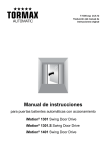
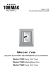
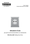
1
T-1321 e 10.08 Operating Instructions for Automatic Sliding Doors iMotion® 2301 Sliding Door Drive iMotion® 2401 Sliding Door Drive Content 1 Regarding these Instructions 3 2 Safety 4 2.1 2.2 2.3 Preconditions for the Operation of the System Permissible Use Taking the System Out of Service in Case of Fault 4 4 4 3 Functions of the System 5 3.1 3.2 3.3 3.4 3.5 3.6 Operating Modes Automatic Door Operation with Sensors Traffic Control Automatic System Monitoring Electromechanical Lock Operation on Power Failure 5 5 5 5 5 6 4 Commissioning 6 5 Operation 6 5.1 5.2 5.3 Operation Through TORMAX User Interface Operation through 3-Position Switch Operation on Power Failure 7 7 8 6 Operating Modes 8 7 Maintenance 9 7.1 7.2 7.3 Cleaning and Maintenance Checks by the System Operator Annual Maintenance and Inspection 8 Trouble Shooting 12 9 Additional Notes 14 9.1 9.2 9.3 9.4 Technical Data Warranty Claims Optional Extras Disposal First edition: 10.08 We print on environment-friendly paper bleached without chlorine. The companies Landert Motoren AG and Landert GmbH are certified according to ISO 9001. 2 Operating instructions iMotion 2301/ 2401 T-1321 e 9 9 11 14 14 14 14 1 Regarding these Instructions Addressee/Status The person responsible for operation and maintenance of the system is referred to as “system operator”. The system operator is responsible for the operation and maintenance of the system. Area of Application This document is applicable for sliding doors with TORMAX automatic door operator of type: iMotion® 2301 Sliding Door Drive iMotion® 2401 Sliding Door Drive Explanation of Symbols In these instructions we have marked all positions which concern your safety with this symbol. This symbol warns of electrical voltage. Text passages in grey background must be absolutely observed for sound operation of the system! Disregard may cause material damage. < Operating functions that are marked by the accompanying symbol correspond to the basic settings; however, the fitter can reprogram them. This symbol marks optional components, which are not installed in all systems. Symbols for Operating Modes Operating mode OFF Operating mode EXIT Operating mode AUTOMATIC 1 Operating mode OPEN Operating mode AUTOMATIC 2 P Operating mode P Manual Operation Languages These instructions are available in different languages. Please ask your TORMAX dealer. Applicable Documents In the system test book, checks are listed that must be performed on periodic examination of the system (see also section 7.3). The location of the test book is at the respective door system. System test book: T-879 e Operating instructions iMotion 2301/ 2401 T-1321 e 3 2 Safety 2.1 Preconditions for the Operation of the System The door system was planned, installed and checked by qualified professionals with regard to performance and safety before it was handed over to the system operator. The system operator was instructed by the installation company concerning operation and maintenance of the system as well as the dangers associated with system operation. Prior to commissioning of the door, these operating instructions – in particular the safety notes – are to be perused and they must be observed! In addition to the operating instructions, the generally applicable legal and the safety-relevant regulations and rules of industrial medicine for accident prevention and for environmental protection in the respective country, in which the system is operated, are also applicable. The responsibility for the instruction of the service personnel, the permissible use and the adherence to the maintenance regulations lies with the system operator. Get acquainted with the operation of the system by studying the operating instructions. Use the system only in a technically sound condition. Safety devices may not be removed or made ineffective. Make sure that possible fault situations are eliminated immediately by qualified professionals. For a most secure and reliable operation of the system, the door automation system must be serviced at least annually and submitted to a safety-relevant examination by a qualified professional trained for this kind of work. If this work is not carried out by the designated person, the manufacturer will reject any product liability and warranty. 2.2 Permissible Use The door automation system TORMAX iMotion 2301 and iMotion 2401 Sliding Door Drive is built according to the current state of technology as well as the recognized safety-relevant rules. The sliding door system is intended exclusively for the deployment in dry rooms and/or, for outer doors, at the inside of a building in the pedestrian passageway. The operator can only be used at the exterior of a building if additional protective measures are taken and under observance of the acceptable environmental conditions. Any other use, or any use exceeding this aim, is deemed as not used in accordance with its intended purpose. The manufacturer will not be liable for damages resulting from such applications. The risk will be borne entirely by the operator of the door system, i.e. the system operator. Arbitrary changes to the system will exempt the manufacturer from any liability for damage resulting from this. 2.3 Taking the System Out of Service in Case of Fault The door automation system must be taken out of service as soon as faults or deficiencies occur that may impair the safety of people. • Switch off the mains supply to the system • Select operating mode “P” if system operation will be continued by means of the internal battery backup system. • Open the door manually if it is installed in an escape route. For information relating to fault indication and trouble shooting see chapter 8. 4 Operating instructions iMotion 2301/ 2401 T-1321 e 3 Functions of the System 3.1 Operating Modes The door automation system can be operated through the TORMAX user interface u with 6 operating modes and status display or optionally through a simple rocker switch u with 3 operating modes. 3.2 Automatic Door Operation with Sensors In automatic operation (operating mode AUTOMATIC 1), the door opens automatically to both sides through sensors when a person approaches. In exceptional cases, it opens through deliberately to be activated switching devices such as push buttons or card readers for controlled access. A key switch usually permits access to the door from the outside also in operating mode EXIT or OFF. The door unlocks, opens and closes again as soon as no further sensors are activated any more after expiry of a separately adjusted hold-open time. The sensors for the door opening and the maintained opening of the door are arranged and adjusted in such a way that the door opens promptly and remains open as long as a person is within the operating range of the door leaf. The door can close nevertheless but only after an attendance time of approx. > 1 minute. The reduced closing speed, which is adjusted by the fitter and adapted to the door weight, in combination with a force of < 150 N, prevents an excessive impact on a person by the moving leaf. Additionally, the obstacle is detected by the control system and an automatic reversal of the door is initiated. Sensors for safeguarding the moving leaves can also be present in opening direction depending upon the surrounding conditions (e.g. column near the operating range) and design of the system (safety clearances). When a person moves into the danger area, the door leaf stops or slows down to a very low speed depending upon the adjustments performed by the fitter. 3.3 Traffic Control The passageway can optionally be blocked in one direction (operating mode EXIT) or be completely closed (operating mode OFF). In these operating modes, an optional electromechanical lock can be used for protection from unauthorized access. For protection from environmental influences (wind / cold weather / heat), the door can be operated with a smaller opening width (operating mode AUTO-MATIC 2). 3.4 Automatic System Monitoring The control system monitors the safety sensors by cyclic active testing. Further, the control system performs continuously internal system tests. On failure of a safety-relevant component, the system changes automatically into a safe state. Thereby, the fault number is displayed on the user interface. Please refer to chapter 8 “Trouble Shooting” for further information. 3.5 Electromechanical Lock The system can be locked in the closed position through an optional electromechanical lock in operating mode OFF and optionally also in other operating modes (e.g. EXIT). Operating instructions iMotion 2301/ 2401 T-1321 e 5 The locking facility is monitored. A possible fault in the lock operation can thus be displayed immediately on the user interface. Details see chapter 8 “Trouble Shooting”. On power failure the locking facility can be activated directly through the optional manual control. 3.6 Operation on Power Failure The following functions are possible according to specifications. • Immediate emergency opening activated through a mechanical energy storage. • Immediate emergency closing through a mechanical energy storage. • Immediate unlocking (if programmed by the fitter). • Continued operation of the system through a battery unit during a determined time with door opening before the battery shuts down. In operating mode OFF the door remains locked. • Unlocking and opening of the from the outside through the key switch and through the battery unit. 4 Commissioning Before switching on mains supply: • Unlock the optional mechanical locking mechanisms e.g. floor lock. • Make sure that the operating range of the door leaves is free of items such as umbrella stands or trolleys. • Check if the floor guide (particularly a continuous guide) is clean and free from items (e.g. pebbles or snow). • Switch on mains voltage and select the operating mode, e.g. AUTOMATIC 1. The first motion after switching on mains supply for the first time takes place slowly with indication of H61 and H62. Thereby, the control system checks the travelling path of the door leaf and determines the end position. The door is now ready for use. 5 Operation The following operating devices are available for the operation of the system depending upon outfit. - TORMAX user interface u - Lock for user interface u - TORMAX 3-position switch u - Key switch u or card readers outside u - Manual control for door lock u 6 Operating instructions iMotion 2301/ 2401 T-1321 e Systems without user interface or 3-position switch are either provided with a fixed operating mode, e.g. AUTOMATIC 1, or are centrally controlled by a time clock (e.g. OFF / AUTOMATIC 1). Push buttons, elbow switches etc. can be installed in place of, or in addition to the sensors. 5.1 Operation Through TORMAX User Interface Selection of the Operating Modes Symbols for operating mode Selection key 1 upwards OFF AUTOMATIC 1 Electr. door lock AUTOMATIC 2 Additional operating mode P EXIT OPEN T1321_1e Selection key 2 downwards • Unlock optional lock for user interface. • Press selection key 1 or 2 briefly. The corresponding operating mode is displayed. Indication of Faults E.g. H31 or E11 For the significance of the indication see chapter 8. • Reset the indication by briefly pressing selection key 2 System Reset • Press selection key 2 for at least 5 seconds. The software is restarted. Subsequently, the control system performs a calibration run, checks the travelling path and searches again for the end positions. The display shows H61 and H62. 5.2 Operation through 3-Position Switch Selection of the Operating Mode OFF AUTOMATIC 1 OPEN T1165_10 The operating mode can be set directly. (System reset by separating the system from mains supply for at least 5 seconds.) Operating instructions iMotion 2301/ 2401 T-1321 e 7 5.3 Operation on Power Failure Manual Lock u 1. Turn manual control in clockwise direction 2. Push the door closed by hand until the lock bolt latches. When the power returns, operating mode OFF is selected automatically due to the engaged door lock. Manual Disengagement u 1. Turn manual control in the counter-clockwise direction 2. Push the door open by hand. Opening Through Key Switch with Battery Unit u • Actuate the key switch for at least 3 sec. and turn it back again. The battery is switched on through the wake-up function. The door is unlocked and opened. The battery switches off again. 6 Operating Modes Operating Mode OFF The activators inside and outside are not observed. The door is pushed close by the motor and is locked by the electromechanical door lock u. Access is only possible through the key switch. < After the operating mode OFF has been selected, the door can still be used for 5 seconds. The door locks after this time has expired and as soon as it is closed. This transition is indicated on the user interface by a flashing display of the operating mode OFF. Operating Mode AUTOMATIC 1 The operating mode AUTOMATIC 1 is commonly used for operation during the day. The door opens automatically to both sides through the inside and outside sensors and usually to the full opening width. Operating Mode AUTOMATIC 2 < The operating mode AUTOMATIC 2 is commonly used for operation during the day. The door opens automatically to both sides through the inside and outside sensors and usually to a reduced opening width. If necessary, the hold-open time can be adjusted by the fitter (different from AUTOMATIC 1). Operating Mode EXIT < 8 The operating mode EXIT is commonly used for operation before closing time. The door opens automatically only through the sensor inside. During the door opening, the sensor outside is observed likewise for safety reasons. The opening width is determined by the preceding selection of the operating mode AUTOMATIC 1 or AUTOMATIC 2. Aditionally the door can be locked automatically by the door lock u. Operating instructions iMotion 2301/ 2401 T-1321 e Operating Mode OPEN The door opens and stops in the open position. The opening width is determined by the preceding selection of the operating mode AUTOMATIC 1 or AUTOMATIC 2. P Operating Mode P Manual Operation The door leaves are freely movable. This operating mode can be used for the cleaning of the door leaves and floor guide or for a temporary shut down of the system. A system reset takes place after quitting this operating mode. 7 Maintenance The system was inspected and accepted by a qualified professional before initial operation. The manufacturer recommends making arrangements for a service contract so that the value of the system is maintained for as long as possible and the system operates reliably and safely in the long term. The following maintenance work is to be carried out. • Regular cleaning of external system parts and floor guides. • Checks by the system operator at least every 3 months. • Annual maintenance and inspection of the system by qualified professionals. Genuine spare parts are to be used exclusively. 7.1 Cleaning and Maintenance • In operating mode “P”, clean the door leaves, casing parts and user interface with a damp cloth using a commercial cleaning agent. • In operating mode “P”, remove dirt from the floor guide and clean it with a damp cloth. • Check the door system and operating devices outside visually for recognisable damages and deficiencies. • Check whether unusual noises can be heard during the motional sequence. 7.2 Checks by the System Operator Extent of the Checks The system operator of an automatic door system must check in periodic time intervals, however at least every 3 months, the performance of the automatic door and the safety facilities. Thus, functional disturbances or safety-endangering changes to the system can be detected early. If faults are determined during the periodic checks, arrangements for getting these repaired by a TORMAX dealer (address see back page of these instructions) must be made immediately. When performing these checks, consider always the possibility of a malfunction of the system! If sufficient free space is not available, do not use any parts of your body for operational tests; use a suitable object as a substitute (e.g. polystyrene or cardboard). Operating instructions iMotion 2301/ 2401 T-1321 e 9 The checks to be carried out by the system operator require only a very low expenditure of time but are essential for a safe and sound operation of the system. The checks by the system operator include: Checking the Sensors • Set operating mode to AUTOMATIC 1. Automatic Motion Detector The motion detector triggers the automatic opening of the door. The sensor must be effective over the total door width. The general flow of traffic and direction of traffic for the given situation are to be considered during these checks. Checks: • Walk through the door in a normal speed. The door starts to open approx. 1.5 – 2 m before it is reached. Immediately before reaching the door, it must already be open to at least 80 % of the opening width. • Perform this check at the entrance and exit sides of the door. T1242_4 Photocell An activated photocell prevents the closing of the door. Depending on the system, one or two photocells are installed on the left and right hand side of the passageway of the sliding door. Checks: • Trigger an opening impulse. The door opens. • Shortly after the door commences to close again, cover the photocell with your hand. The door must open again. • Perform the check with the second photocell (if available). T-787/5 Combined sensors with motion detectors and presence detectors These sensors prevent being hit or squeezed by the moving leaves. Checks: • Walk slowly towards the door. The door opens. Stop between the door leaves and wait max. 1 min. The door must not close. • Perform this check at the entrance and exit sides of the door. T1242_3 10 Operating instructions iMotion 2301/ 2401 T-1321 e Mechanical Emergency Opening Facility u Checks: • Simulate a power failure (pull the power plug or switch off the main system switch) or select operating mode P: The door leaves must open fully. Electrical Emergency Opening Facility u Checks: • Simulate a power failure (pull the power plug or switch off the main system switch): The door behaves according to the programmed operating function of the battery unit (see section 3.6). • Restore mains supply. Manual Disengagement u Checks: • Switch off mains supply. Check that the door can be locked and unlocked. • Open the door and lock the lock with the rotary knob. The door must be able to be locked by pushing it closed. • Restore mains supply. 7.3 Annual Maintenance and Inspection Service Interval Service interval is defined under consideration of the frequency of use. However, maintenance and inspection must take place at least once annually by a qualified professional trained for that purpose. Requirements for Maintenance Staff Qualified professionals are persons who have adequate knowledge in the discipline of power operated doors based on their vocational training and experience and who are acquainted with the applicable accident prevention regulations, guidelines and generally recognized rules of that technology to such an extent that they can appraise the safe working condition of power operated doors. These persons include for example professionals of the manufacturing or supplying company and experienced professionals of the system operator. Qualified professionals have to submit their expertise objectively from the point of view of accident prevention and must not be influenced by other requirements, e.g. financial demands. Maintenance work on electrical parts must be performed by an electrical fitter. Extent of Maintenance Work The extent of maintenance work is set out by the manufacturer. The inspection may only be carried out by a person trained for that purpose as specified by the manufacturer. Test Book The findings of the inspection are finally entered into the test book. The test book is to be kept by the system operator at a save place. Operating instructions iMotion 2301/ 2401 T-1321 e 11 8 Trouble Shooting Malfunctions become evident by unusual behaviour of the door and / or as a result of an error message on the user interface. Error messages appear on the user interface as a flashing “E” or “H” followed by two figures. Indication H = information the operation of the system can be continued. Indication E = fault the system has stopped. It must be repaired. Some malfunctions can be quickly rectified by restarting the door drive with a software reset and/or briefly switching off the power supply to the door drive. Display and reset of the error with TORMAX user interface Step through the faults on the display (if several faults are displayed) 1. Reset the error message 2. Push 5 s for software reset T1242_2 Fault reset with 3-position switch T1238_4 Software reset in the event of a breakdown: change operating mode. Fault reset by cutting off the power supply Installations without battery unit: cut off power supply for approximately 10 s If the malfunction cannot be rectified or if it re-occurs after a short time, you should arrange for it to be rectified by a fitter from your TORMAX dealer. In this case, note the error number and pass the information to the specialist. Address see back page or service label at the system. Fault Table Behaviour of the System No. Cause Remedial Action / Reset Door stops during opening. H91 Remove obstacle. Clean floor guide in operating mode P. Door reverses during closing. H92 Door stops repeatedly during opening. H93 Door stops repeatedly during closing. H94 Information for search run. H61 H62 Electronic obstacle recognition on opening by a person, wind pressure, ventilation or dirt in the floor guide. Electronic obstacle recognition on closing by a person, wind pressure, ventilation or dirt in the floor guide. Electronic obstacle recognition on opening in the same position by stationary obstacle. Electronic obstacle recognition on closing in the same position by stationary obstacle. Search run of the door after reset or after power recovery. Door functions with reduced speed. H71 Battery operation 12 Operating instructions iMotion 2301/ 2401 T-1321 e Remove obstacle. Clean floor guide in operating mode P. Remove obstacle. Clean floor guide in operating mode P. Remove obstacle. Clean floor guide in operating mode P. Allow the search run to be completed. Wait for power recovery Switch on mains supply. Behaviour of the System No. Cause Remedial Action / Reset Door remains closed. – Operating mode like for instance “OFF” “EXIT “ or “P” E.g., select operating mode AUTOMATIC 1. Door remains open. – Operating mode like for instance “OPEN” or “P” E.g., select operating mode AUTOMATIC 1. Door does not lock in OFF. E11 Lock is jammed or defective. Door does not open after changing from OFF to AUTOMATIC. Lock produces periodic switching noise. Door does not open in OFF through the key switch. Lock produces switching noise. Door remains closed. E11 Lock is jammed or defective. In operating mode OFF and closed door: Press the door leaves for a few seconds against the closed position. Select operating mode AUTOMATIC 1: Press the door leaves briefly against the closed position. E11 Lock is jammed or defective. Turn on key switch and subsequently press the door leaves briefly against the closed position. E31 Remove the objects within the range of the sensor. Door remains open. E32 Door does not open or close E33 Door does not open or close Door remains open. E34 Safety facility in opening direction is permanently active (> 1 min.) or defective. Safety facility in closing direction is permanently active (> 1 min.) or defective. Safety facility in opening direction is permanently active (> 1 min.) or defective. Safety facility stop is permanently active (> 1 min.) or defective. Activator inside is active > 1 min. Activator outside is active > 1 min. Key switch is active > 1 min. Deviation in the travelling path. Fixed obstacle in the travelling range. Door stops. E41 E42 E43 E5.. Door stops. E61 E62 Power supply is overloaded or voltage too low. Door stops. E64 E65 Drive/control system is overheated. Door remains open. E.. Control unit safety power off Door hits a person. E8.. – Remove the objects within the range of the sensor. Remove the objects within the range of the sensor. Remove the objects within the range of the sensor. Get sensor adjusted by a professional. Reset key switch. Remove firm obstacle in the travelling range of the door. Perform a software-reset. Get the power supply and connections checked by a professional. Perform a software-reset. Wait for the automatic reset after cooling down. Avoid exposure to the sun. Perform a software-reset. Safety facility or adjustment inadequate. Shut down the system. (see section 2.3) Operating instructions iMotion 2301/ 2401 T-1321 e 13 9 Additional Notes 9.1 Technical Data Door operator types iMotion 2301 Sliding Door Drive iMotion 2401 Sliding Door Drive Drive system Electromechanical sliding door operator with direct drive through AC permanent magnet synchronous motor with external rotor Control system Control Unit MCU32 Mains connection 1 x 230 / 1 x 115 V AC, 50 – 60 Hz, 10 A Power consumption iMotion 2301 max. 190 W iMotion 2401 max. 310 W Sensor power supply iMotion 2301 24 V DC (+0.5 – 1.5 V) 0.75 A iMotion 2401 24 V DC (+0.5 – 1.5 V) 1.5 A in battery operation min. 16.5 V Protective class of drive IP 22 Ambient temperature –20 °C to +50 °C Outputs iMotion 2301 24 V DC short circuit proof (within power supply 0.75 A in total) iMotion 2401 24 V DC short circuit proof (within power supply 1.5 A in total) Approvals CE incl. RoHS, TÜV, ETL Standards DIN 18650, EN 60335-1, EN 61000-6-2, EN 61000-6-3, UL 325 9.2 Warranty Claims Malicious or wilful damage to and contamination of system components as well as modifications to the drive and control system by third parties renders all warranty claims null and void. 9.3 Optional Extras The following are some of the optional extras which are available: electro-magnetic lock, key switch, security features and a range of activators. Please ask your TORMAX dealer for more information. 9.4 Disposal This system must be properly dismantled at the end of its working life and its disposal carried out in accordance with national regulations. We recommend that you contact a specialist disposal company. When disassembling the battery module, there is a potential hazard from acid! The tension of the rubber cord must be relaxed carefully! Contents subject to technical changes! 14 Operating instructions iMotion 2301/ 2401 T-1321 e Your First Choice for Automatic Doors TORMAX Sliding Doors TORMAX Swing Doors TORMAX Folding Doors TORMAX Revolving Doors TORMAX Slide-Swing Doors Manufacturer: Advice, sales, installation Repairs and service: TORMAX | CH-8180 Bülach-Zürich Phone +41 (0)44 863 51 11 Fax +41 (0)44 861 14 74 Homepage www.tormax.com E-Mail [email protected] TORMAX is a Division and a registered trademark of Landert Motoren AG