1
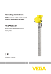
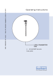
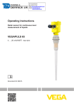
4 Mounting
Fig.7:Mountingofthesensorwithinflowingmedium
Measuring range
The reference plane for the measuring range of the sensors is the
sealing surface of the thread or flange.
Keep in mind that a min. distance must be maintained below the reference plane and possibly also at the end of the probe - measurement
in these areas is not possible (dead band). The length of the cable
can be used all the way to the end only when measuring conductive
products. These blocking distances for different mediums are listed
in chapter "Technicaldata". Keep in mind for the adjustment that the
default setting for the measuring range refers to water.
Pressure
The process fitting must be sealed if there is gauge or low pressure in
the vessel. Before use, check if the seal material is resistant against
the measured product and the process temperature.
The max. permissible pressure is specified in chapter "Technical
data" or on the type label of the sensor.
Standpipes or bypass
tubes
Standpipes or bypass tubes are normally metal tubes with a diameter
of 30 … 200 mm (1.18 … 7.87 in). In measurement technology such a
tube corresponds to a coax probe. It does not matter if the standpipe
is perforated or slotted for better mixing. Lateral inlets with bypass
tubes also do not influence the measurement.
Microwaves can penetrate many plastics. For process technical reasons, plastic standpipes are problematic. If durability is no problem,
then we recommend the use of metal standpipes.
Generally a spacer at the probe end is sufficient for rod probes to
avoid contact to the tube wall. Depending on the tube diameter or
tube length, spacers can be also mounted in the centre of the tube.
With cable probes it is also possible to strain the cable.
16
VEGAFLEX 83 • 4 … 20 mA/HART - two-wire
41834-EN-120726
When the VEGAFLEX 83 is used in standpipes or bypass tubes,
contact with the tube wall must be avoided. We recommend for this
purpose a cable probe with centering weight.